P.B.M. SE User manual

TECHNICAL MANUAL "SE"(PBM753) Revisionno. 1dd. 01/02/2017
P.B.M. S.r.l. viaBarella, Z.I. -VIGNOLA(MO )ITALIATel. +39 (059)7705311 Fax+39 (059)7705300
http://www.gruppopbm.it e-mail : pbm@gruppopbm.it file: ManualeSE PBM753 GBrev.1.doc
TECHNICALMANUALFOR
“SE”
BATTERYCHARGER
(withPBM753 electroniccardSWV1.1)
HANDBOOKFORAUTHORIZEDTECHNICIANSAND SERVICEPERSONNELONLY

TECHNICAL MANUAL "STAR"(PBM750 rev2 SW2.2) Revisionno. 1dd. 01/02/2017
P.B.M. S.r.l. viaBarella, Z.I. -VIGNOLA(MO )ITALIATel. +39 (059)7705311 Fax+39 (059)7705300
http://www.gruppopbm.it e-mail : pbm@gruppopbm.it file: ManualeSE PBM753 GBrev.1.doc
page 1
CONTENTS
CHAPTER1: INTRODUCTION.........................................................................................................................2
CHAPTER2: DESCRIPTIONOF THEPBM753 CONTROLCARD ..................................................................2
2.1: MAINFEATURES OF THE PBM753 CARD ......................................................................................................3
CHAPTER3: COMMISSIONING AND STARTUP.............................................................................................4
CHAPTER4: SETTING OF THEBATTERYVOLTAGE, ADJUSTMENT OF THETHRESHOLD (GASSING)
VOLTAGE, AND CHARGING STAGES............................................................................................................4
4.1: CARD SETTINGONBATTERYCHARGERWITHOUTBATTERY .............................................................................5
CHAPTER5: BATTERYCHARGERFUNCTIONS..........................................................................................5
CHAPTER6: DESCRIPTIONOF THECHARGE.............................................................................................6
FLOATING CHARGE....................................................................................................................................7
7.1. BATTERYDISCONNECTION UNDERCHARGE.............................................................................................8
7.2CURRENTDELIVERY DURINGANOFF STAGE .................................................................................................8
7.3FAILURETODELIVERCURRENT DURINGANONSTAGE ...................................................................................8
7.4SAFETYTIMER............................................................................................................................................8
CHAPTER8: LEDINDICATIONS.....................................................................................................................8
CHAPTER9: INSTALLATION, SAFETY, FAILUREDETECTION, AND MAINTENANCE.................................9
9.1: INSTALLATION......................................................................................................................................9
9.2: SAFETYNOTES ....................................................................................................................................9
CHAPTER10: FAILUREDETECTION............................................................................................................ 10
10.1: NECESSARYINSTRUMENTS.......................................................................................................... 10
10.2: FIRST CHECKS TO BE PERFORMED............................................................................................. 10
10.3: FAILUREDETECTIONAND MEASURES ........................................................................................ 10
CHAPTER11 : MAINTENANCEAND CLEANING.......................................................................................... 16
CHAPTER12: WIRING DIAGRAMS AND PARTSLIST................................................................................. 17
TECHNICAL MANUAL "SE"(PBM753) Revisionno. 1dd. 01/02/2017
P.B.M. S.r.l. viaBarella, Z.I. -VIGNOLA(MO )ITALIATel. +39 (059)7705311 Fax+39 (059)7705300
http://www.gruppopbm.ite-mail : pbm@gruppopbm.it file: ManualeSE PBM753 GBrev.1.doc
page 2
CHAPTER1:INTRODUCTION
AsofSeptember2016,the “SE” series battery chargerhasbeen renewed bothexternally,withacabinet
supplied withnewcoloursand anewgraphicalpanel,and technicallybyadding anewcircuitboard.The main
technicalfeaturesare:
•New PBM-753 cardat microprocessor, adaptableforthree-phaseand singlephasebattery charger.
•SMDtechnologycomponents.
•Battery chargeroperating range withrated voltage from24Vto96V.
•Card powered bymainsonly (24Vac).
•ON/OFF relay24VAC/10Awithcontactson connector.
•Battery chargerfunctionsconfiguration jumpersset bythe useraccording torequirements.
•Newfunctioning configuration options: 3h Autostart, Safetytimersettableat 11h.
•NewEqualisation and Floating charge mode.
•2calibration modesavailable: preset mode and adjustablemode.
•ON/OFF button integrated on the card.
•Jumperformanualrelaydrive.
•Powersupplyfusetoprotect the card(fromincorrect setting ofbattery selection jumpers)
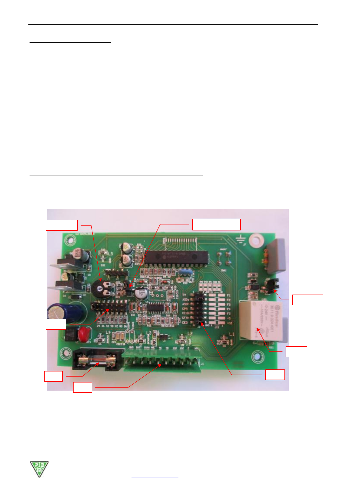
CHAPTER2:DESCRIPTIONOF THEPBM753 CONTROL CARD
The twopicturesbelowshowthe maincomponentsbothon the side ofcomponentsand weldingsofthe card.
Figure2a : PBM753 –side ofcomponents
RL1
RL1
ON
J1
F1
V_GAS
J
10
J2
J9: FIX-REG
TECHNICAL MANUAL "SE"(PBM753) Revisionno. 1dd. 01/02/2017
P.B.M. S.r.l. viaBarella, Z.I. -VIGNOLA(MO )ITALIATel. +39 (059)7705311 Fax+39 (059)7705300
http://www.gruppopbm.ite-mail : pbm@gruppopbm.it file: ManualeSE PBM753 GBrev.1.doc
page 3
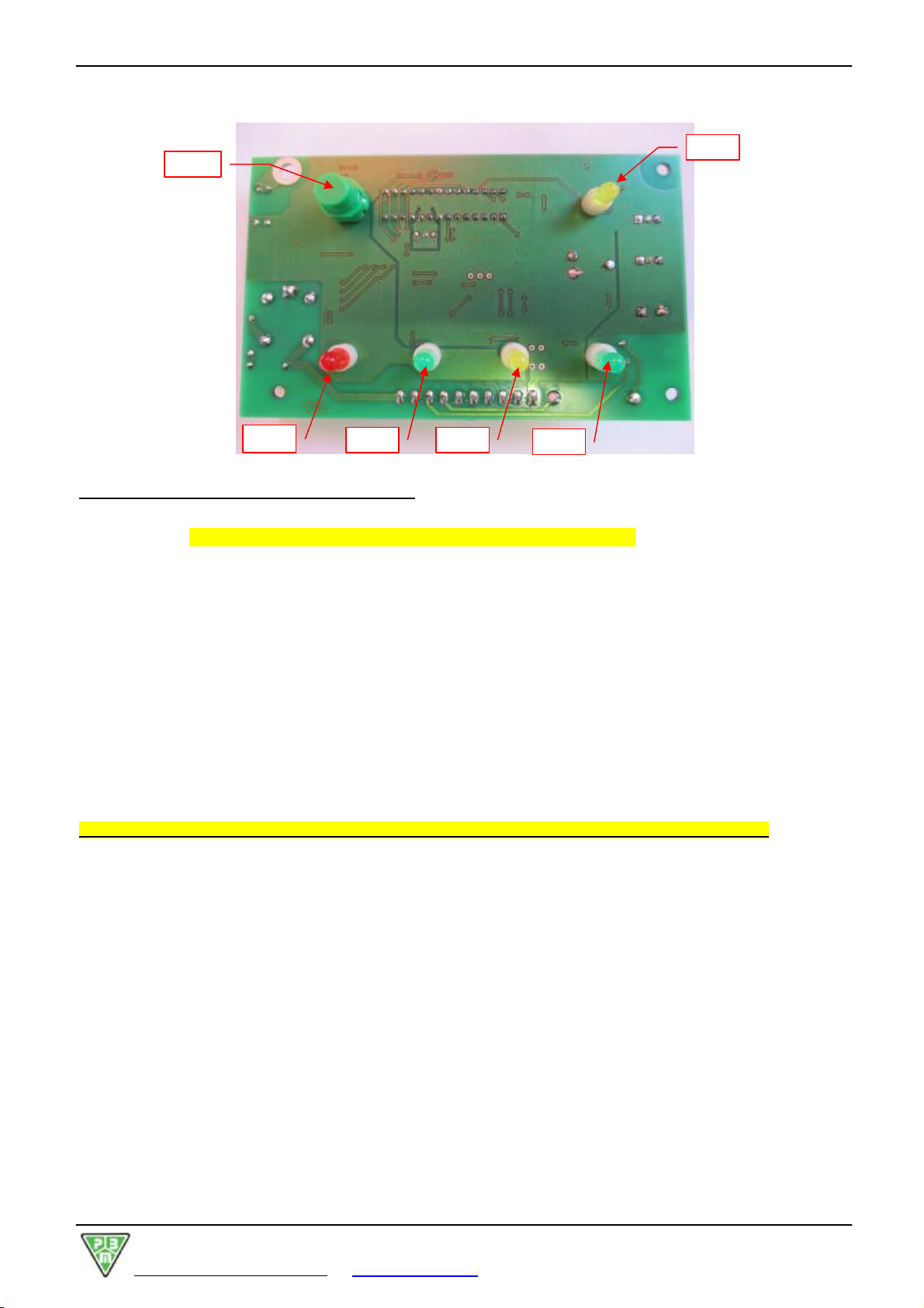
Figure2b : PBM753 –side ofweldings
2.1:MAINFEATURES OF THEPBM753 CARD
RL1ON:Manualcharge: connecting the jumperRL1 on, the relayisclosed manually
Warning:thebattery charger can bestopped manuallyonly.
J2 Function selection
TV Quick test(itallowstoshortlycheck the operation ofthe battery charger:the internalclock is
accelerated and the charging process issimulated)
AS5s Autostart withadelayof5seconds
AS3h Autostartwithadelayof3hours(the automaticstartofthe chargerisenabled 3hoursafter
connection topower)
CPR Proportionalcharge
CI11h Safetytimerset at 11 hours(instead of9, whichisthe default setting)
CF4h 4h-long finalcharge (instead of3, whichisthe default setting)
CEQ Equalizing charge
J9 2-position jumpertoselect the gassing voltage setting mode (FIX, fixed, or REG., adjustable)
J10 Selection ofbattery rated voltage (24V-36V-40V-48V-72V-80V-96V)
NOTE:ALL THETIMES YOUCHANGES THEJUMPERSSETTING, RESETALSO MAINSAND BATTERY!
VGAS One-turntrimmertoset the gassing point (2,4V/cell)
RL1 ON-OFF relay
L5 LEDindicating the EQUALIZING CHARGE(yellow)
L4 LEDindicating aFAULT (red)
L3 LEDindicating END OF CHARGE(green)
L2 LEDindicating FINALCHARGE(yellow)
L1 LEDindicating BATTERYCONNECTED/ CHARGING PROCESS (green)
F1 500 mAfuse, 5x20 fuse, asaprotection on cardpowersupply
P1
L1
L
2
L
3
L
4
L
5
TECHNICAL MANUAL "SE"(PBM753) Revisionno. 1dd. 01/02/2017
P.B.M. S.r.l. viaBarella, Z.I. -VIGNOLA(MO )ITALIATel. +39 (059)7705311 Fax+39 (059)7705300
http://www.gruppopbm.ite-mail : pbm@gruppopbm.it file: ManualeSE PBM753 GBrev.1.doc
page 4
J1 Connection connector, inwhich:
1=-shunt (negativepole)
2=+battery (positivepole)
3=+shunt
4=ON-OFF button
5=
6=
7=24VAC
8=24VAC
9=relaycontact
10 =relaycontact
CHAPTER3:COMMISSIONING AND STARTUP
The PBM753 cardispowered frommainsbymeansofa24VACauxiliary transformerwithan inputof100mA
max. Thereforeno message isdisplayed onlybattery connection.
Onconnecting alsomains, the PBM753 cardperformsatest lighting up all LED’s.
Oncethe self-test hasbeen completed, onlythe green “BATTERYCONNECTED”LED(L1)remainslit.
NOTE: a24Valternated current, generated bythe auxiliary transformer,powersthe card.Ifthe chargeris
powered frommainsand the carddoesnotswitchon,check the corresponding circuit(frommainsinputtothe
cardthrough the auxiliary transformer).
CHAPTER4:SETTINGOF THEBATTERYVOLTAGE,ADJUSTMENTOF THETHRESHOLD(GASSING)
VOLTAGE, AND CHARGING STAGES
•Selectbattery voltage byinserting the J1 jumpersaccording tothe rated voltage ofthe installed battery.It
ispossibletoset 24V, 36V, 40V, 48V, 72V, 80V, and 96V.
•Afterthe J10 jumperhasbeen properlyset, the cardautomaticallysetsthe voltage value corresponding to
the gassing voltage, whichmayrange between 2,3and 2,5V/cell.
•By turning the one-turn VGAS trimmer,itispossibletosetthe gassing voltage withavery high accuracy,
asdescribed inChapter4.1.
•The PBM753 cardfeaturestwomodesofgassing voltage setting bymeansofthe J9 jumper:
•By setting the J9 jumper toFIX,thegassing threshold issetto2.4V/cell withanerrorof±0,05V,due
tothe componentstolerance.
•Setting the J9 jumper toREG., the gassing voltage can be setwiththe highestaccuracy (±0,01V/cell)by
meansofthe one-turnVGAS trimmer.
•NOTE:Thecalibration at2,4V/cell)once itisdone, itremainsvalid (with an accuracy of±0,02V/el.)
forall battery voltages.
At roomtemperature(25°C), the standardSETTING VALUES arethe following:
Nominal
Voltage battery Calibration valueswithEXACT setting –
J9>REG (2,4V/el.) Calibration valueswithQUICKsetting –
J9>FIX(2,4V/el.±0,05)
24 V 28,8V 28,3V÷29,2V
36 V 43,2V 42,6V÷43,8V
40 V 48,0V 47,3V÷48,7V
48 V 57,6V 56,7V÷58,4V
72 V 86,4V 85,1V÷87,7V
80 V 96,0V 94,5V÷97,4V
96 V 115,2V 113,5V÷116,9V
•Pleasenotethatthe above-mentioned voltage istobe measured on battery side.Ifthe cardisnotseton
site, the VGAS trimmerhastobe calibrated foravoltage, measured on the card, exceeding the rated value
by0,3-0,4V. Thisallowstotakeintoaccount the voltage drop whichusuallyoccurson the charging cables.
•Onreaching the thresholdvalue, the yellowLD4 LEDlightsup.
•Ifthe thresholdvoltage isexceeded formorethan 10 seconds, the LD4 LEDremainslit.
•Thereforethe thresholdsetting hastobe completed withinthat time.

TECHNICAL MANUAL "SE"(PBM753) Revisionno. 1dd. 01/02/2017
P.B.M. S.r.l. viaBarella, Z.I. -VIGNOLA(MO )ITALIATel. +39 (059)7705311 Fax+39 (059)7705300
http://www.gruppopbm.ite-mail : pbm@gruppopbm.it file: ManualeSE PBM753 GBrev.1.doc
page 5
4.1:CARD SETTING ONBATTERYCHARGERWITHOUTBATTERY
Material required:
•DC voltage generatorfrom0Vto150V(e.g. PBM SLV150)
•digitalvoltmetertomeasureDC voltagesranging from0Vto400V
•thinscrewdrivertomakeadjustments
Procedure:
•Disablethe AUTOSTART function removing the AS5sand/orAS3h jumpers
•Warning:disabling the AUTOSTARTfunction isnecessary topreventthe battery chargerfromfeeding
powertothe stabilized powersupplythusdamaging it.
•Connect the battery chargertomains.
•Powerthe chargerfromthe voltage generatorbymeansof the charging cables,afteradjusting the voltage
generatortothe desired voltage threshold.
•Foralead battery witharated voltage of48V(24 cellsx2,00V/cell)the voltage thresholdgenerally
correspondsto2,4V/cell +0,3V,equalling the average drop value on the charging cablesduring the
charging process. Therefore, the battery input voltage must be 2,40 x24 +0.3=57.9Volts.
•Useathinscrewdrivertoturnthe VGAS trimmeron the PBM753 cardcounter-clockwiseuntil the yellow
LD4 LEDlightsup.Ifthe LEDisalreadylit, turnthe VGAS trimmerclockwiseuntil the LEDlightgoesoff,
then turnit counter-clockwiseuntil it lightsup again.
Warning :to avoid damaging thepower supply, becareful notto push theON-OFF button.
NOTE :Ifthe yellow L2 LEDremainslitlongerthan 10 seconds,itmeansthatthe chargerhaspermanently
switched tothe finalcharge stage (the LEDlightwill notgo off anymore, even ifthe battery voltage fallsbelow
2.40V/cell).
In thiscase resetthemainsand make theprocedure again.
CHAPTER5:BATTERYCHARGERFUNCTIONS
•QUICK TEST: byconnecting ajumperto J2 at TV the controlSWacceleratesall the timerssuchasthe
safetytimer,finalcharge timerand equalisation times.Thisfunction isusefulforquick overall check of the
battery chargerworking cycle.
•FINALCHARGEof4h: connecting ajumperon J2 at CF4h lengthensthe finalcharge timefrom3h to4h.
•AS5: connecting ajumperon J2 at AS5s enablesthe automaticcharging startfunction (AUTOSTART)5
sec. afterthe battery hasbeen connected.
•AS3h: connecting ajumperon J2 at AS3h enablesthe automaticcharging startfunction (AUTOSTART)3
hoursafterthe battery hasbeen connected.
•PROPORTIONALCHARGE: connecting ajumperon J2 at CPR enablesthe proportionalcharge bywhich, if
the battery reachesthe gassing thresholdwithinthe first 20 minutesofcharging, the finalcharge iscarried
out for10 minutes. Thisfunction istoprotect the battery alreadycharged and recharged anothertimeby
mistake.
•Ifthe electroniccardPBM753 detectsthe reaching ofthe final charge thresold(yellowled lighting )
within thefirst20 minutes, the charge goeson forother10 minutes(total20+10 =30 minutesmax)
and then it finallystopsshowing “charge completed “through the green led.
•Ifit isnot sothe charge continuesuntil it reachesthe finalcharge thresoldand goeson for3hours(orthe
timeset )and, tofollowthe equalization charge (ifprogrammed).
•CI11h: connecting ajumperon J2 at CI11h setsthe safetytimerat the first stage at 11h
•CEQ: connecting ajumperon J2 at CEQ activatesthe equalisation and floating function.

TECHNICAL MANUAL "SE"(PBM753) Revisionno. 1dd. 01/02/2017
P.B.M. S.r.l. viaBarella, Z.I. -VIGNOLA(MO )ITALIATel. +39 (059)7705311 Fax+39 (059)7705300
http://www.gruppopbm.ite-mail : pbm@gruppopbm.it file: ManualeSE PBM753 GBrev.1.doc
page 6
FUNCTIONSUMMARYTABLE
Jumper
symbol Function Description offunction
withoutjumper with jumper
TV Quick test Standardtimes(*) Accelerated times
CF4 Finalcharge time Finalcharge at 3hours(*) Finalcharge at 4hours
AS5s Standardautostart Manualstart Autostart after5seconds(*)
AS3h Delayed autostart Autostart after3hours
CPR Proportionalcharge No proportionalcharge (*) Proportionalcharge on
CI11h Safetytime Safetytimerat 9hours(*) Safetytimerat 11 hours
CEQ Equalisation charge Not programmed Programmed*
*Default setting
CAUTION! : Thecardchecks thesetting ofthejumpers whenitturnson, namelywhenthecharger is
poweredbymains.Tomake modifiedsettingseffective withtheboardpowered, thecharger mustbe
disconnected and then reconnected.
CHAPTER6:DESCRIPTIONOF THECHARGE
Onceall connections(mainsand battery) havebeen performed, the electroniccardPBM 753 makesa lighting
testofall theleds. Afterthistest just the L1 green led ison “BATTERYCONNECTED”and eventuallythe
LED L5 ifalsothe equalizing charge isset.
Charging curve
The charging characteristicshownaboveismade up ofthe following stages:
Initialcharge: performed withdecreasing currentuntil athresholdisreached,corresponding tothe gassing
voltage set bymeansofthe VGAS trimmer(standardvalue is2.4V/cell).
The initialcharge maylast 9or11 hours max (depending on the setting ofthe CI11H jumper).
Ifthe initialcharge isnotcompleted withinthattime,the safetytimeroperatesand the redL4LED lightsup to
signalaFAULT.
Final charge: beginswhen the yellow L2LED (corresponding toathresholdequalto2,4V/cell)lightsup.
It isperformed withdecreasing currentand goeson time-controlled (3hoursasdefaultsetting;4hourswhen
the CF4h jumperisinserted).
TIME
100
I(%)
V/el.
2,40 V
2,00 V.
INITIALCHARGE
MAX 9-11 h
Safety timer
FINALCHARGE PAUSE
50
25
EQUALIZATION
2,70 V.
5impuls
ooo
5impuls
ooo
5impuls
ooo
15h 15h

TECHNICAL MANUAL "SE"(PBM753) Revisionno. 1dd. 01/02/2017
P.B.M. S.r.l. viaBarella, Z.I. -VIGNOLA(MO )ITALIATel. +39 (059)7705311 Fax+39 (059)7705300
http://www.gruppopbm.ite-mail : pbm@gruppopbm.it file: ManualeSE PBM753 GBrev.1.doc
page 7
End ofnormalcharge: when the above-mentioned timehaselapsed,the greenL3LED,indicating
“BATTERYOK”, lightsup.
Then an equalizing charge, ifenabled (CEQ jumper), takesplace.
Pause:60min-long charge interruption whichseparatesthe end ofnormalcharge and the beginning ofthe
equalizing charge.
Equalizing charge:
Afterthe normalcharge apausewill takeplace(T.Pause =60 min)afterwhichEqualizing will be performed
(fora Teq time =45h).
Equalizing ismade up ofacertainamount(Np=3)ofpulse(Neq=5)packages,eachofwhichconsistsof
charges (T.ON=12min)and pauses (T. OFF=48min).
The abovementioned pulsepackagesalternatewithpauses(Ts=15h).
Thesepulsesareperformed during the Active cycle(=45h), followed bya Stop cycle(=120h).
Thisequalizing systemhasno timelimitsand stopson battery disconnection.
The systemisvery usefulduring holidaysand week-ends,sinceitmakesitpossibletokeep battery charged
whilepreventing overcharging, overheating, and/orwaterconsumption.
FLOATING CHARGE
Atthe end ofacompleteequalized charge cycle(45 hours)if the battery remainsconnected (during holidays
forinstance)the equalization cyclesarerepeated every 120 hours(5day)
Thiscycleofcharge,thatcompensatesthe battery self–discharge , isrepeateduntil theuser remove the
battery.
Warning :
•Before disconnecting thebattery,check whether thecharging process has beencompleted. Ifthe
charging process isstill being performed and needsbeing interrupted, press theON-OFF button.
•Never disconnectthebattery connectorbefore interrupting thecharging process !
The charging process can be interrupted withoutdisconnecting battery bypressing the ON-OFF button;inthis
waycharging timesarestored and bypressing the ONbutton again,the charging process isresumed fromthe
point ofinterruption.
Ifbattery isdisconnected during apauseofthe equalizing charge orafterentering the OFF statusbypressing
the relevantpush-button,the battery chargerwill resetand itwill beginanewcharge on connecting the new
battery.

TECHNICAL MANUAL "SE"(PBM753) Revisionno. 1dd. 01/02/2017
P.B.M. S.r.l. viaBarella, Z.I. -VIGNOLA(MO )ITALIATel. +39 (059)7705311 Fax+39 (059)7705300
http://www.gruppopbm.ite-mail : pbm@gruppopbm.it file: ManualeSE PBM753 GBrev.1.doc
page 8
CHAPTER7:FAULTS
The PBM753 cardisabletorecognize4typesoffaults:
7.1. BATTERYDISCONNECTIONUNDERCHARGE
Disconnection ofbattery during acharging process mightbedangerous.
Ifnevertheless battery isdisconnected fromchargerduring acharging process,the charging process will be
temporarilystopped and afaultwill besignalled bymeansoftheyellow L2LEDblinking.
Onconnecting againabattery tothe charger, the cardwill reset and start anewcharging process.
All information concerning the previouscharging timesgo lost.
7.2CURRENTDELIVERYDURING ANOFF STAGE
During an inactive(notcharging)stage the battery chargerdetectscurrentpresencetowardsbattery,and
signalsit bymeansofthe red L4LEDblinking slowly. Thissignalsadefect eitherofthe relayorcontactor.
7.3FAILURETO DELIVERCURRENTDURING ANONSTAGE
During an active(charge)stage the battery chargerdetectscurrent failuretowardsbattery and signalsit by
meansofthe red L4LEDblinking quickly.
7.4SAFETYTIMER
Ifthe safetytimeroperatesduring the initialcharge, the battery chargerstopsthe charging process and signals
it bymeansof thered L4LEDwhich lightsup constant.
To exitfromall faultconditions, thebattery charger needsresetting:disconnectthecharger fromthe
power supplyand connectitagain to it.
CHAPTER8:LEDINDICATIONS
Indication L1
green L2
yellow L3
green L4
red L5
yellow
Onlymainspowersupply OFF OFF OFF OFF ON
Onlymainspowersupply(self-test) ON* ON* ON* ON* ON*
Onlybattery powersupply OFF OFF OFF OFF OFF
Mainsand battery powersupply ON OFF OFF OFF -
Autostart inprogress OFF OFF BL BL BL
Initialcharge BL OFF OFF OFF -
Finalcharge BL ON OFF OFF -
End ofcharging ON ON/OFF ON OFF -
Equalizing charge disabled - - - - OFF
Equalizing charge enabled - - - - ON
Pauseduring the equalizing charge ON ON/OFF ON OFF BL
Equalizing charge BL ON ON OFF BL
ANOMALY/ ALARMS
Mainsfailure NO INDICATION
Battery disconnection during the charging process OFF BL OFF OFF OFF
Current delivered even ifbattery chargerisOFF ON OFF OFF BL OFF
Current 0delivered even ifbattery chargerisON OFF OFF OFF BV OFF
Operation ofthe safetytimer(set at 9or11h) ON OFF OFF ON OFF
ON* on forinitialself-test
OFF off
ONLight constant
BLblinking slowly
BV blinking quickly
-LEDcan be inanycondition
Note:the yellowLD1 LED(equalizing charge)isalwayslit, if the equalizing charge isenabled,oralwaysOFF,
ifthe equalizing charge isdisabled. During the quick test, LED’sblinkmorequickly.

TECHNICAL MANUAL "SE"(PBM753) Revisionno. 1dd. 01/02/2017
P.B.M. S.r.l. viaBarella, Z.I. -VIGNOLA(MO )ITALIATel. +39 (059)7705311 Fax+39 (059)7705300
http://www.gruppopbm.ite-mail : pbm@gruppopbm.it file: ManualeSE PBM753 GBrev.1.doc
page 9
CHAPTER9:INSTALLATION, SAFETY, FAILUREDETECTION, AND MAINTENANCE
Inthischapterthe maininfoareprovided,necessary tothe Service Personnel tocarry outacorrect
installation of the battery charger,aquick detection of the mostcommon failures,and apropermaintenanceof
the unit.
9.1:INSTALLATION
The generalnoteson installation arealreadyprovided inthe usermanualenclosed toeachbattery charger.
Onlythe majoritemsaresummarized below.
•It isessentialtoconnectthe chargertoamainssupplyofstandardscorresponding tothe powerofthe
battery chargerinstalled tobe surethat the chargerfunctionsproperly.
•The chargerisequipped withtapstoadjustthe chargertomains,compensating forpossibledifferences
between the voltage availableat the user’ssiteand the rated voltage.
•The single-phasechargersarepreset forarated voltage of230VAC.
•The three-phasechargersarepresetforarated voltage of400VAC(orother values depending on the
destination country).
•Checking themainsvoltageisessential:amainsvoltage whichistoo high ortoo lowcompared withthe
rated value,mayresultinbigdifferencesinthe currentdelivered bythe battery chargerwithfollowing
malfunction ofthe chargerand lowerperformancesofthe battery.
9.2:SAFETYNOTES
•Ensurethatthe battery chargerispositioned ontoasolid,flat, and even floor,and isprotected against
possibleimpactsfromforklift trucksand othervehicles.
•The battery chargerhastobe installed inasitefree frommaterialswhichmaypreventitsnatural
ventilation, necessary todissipatethe produced heat.
•Do not position the chargernearexplosive, inflammable, and/ordangerousmaterials.
•Makesurethat the battery chargerisneitherexposed torain, moistureorfog, norsplashed withwater.
•Do notinstall itoutdoor*,underunstableshedsorshelters,withthe exception ofspecialversionswith
protection class IPX3orhigher.
•Check the condition ofsockets,fusesand/orswitches,existing atuser’ssite,and ofconnection cables.Do
not usepatchcordstoprolong the existing powercord!!
•Makesurethatthe battery chargerisequipped withan electricalconnectorsuitableforitspowerand current
and it isconnected toan adequatemainssocket!! (check inputsand powerson the rating plate).
•Check connectionsbetween battery and charger:iftheyaredamaged and/orworn-outtheymayproduce
dangerousoverheatings.
•All checks and/orsettingshave tobeperformedbyqualified, skilled, and authorisedpersonnel
only.

TECHNICAL MANUAL "SE"(PBM753) Revisionno. 1dd. 01/02/2017
P.B.M. S.r.l. viaBarella, Z.I. -VIGNOLA(MO )ITALIATel. +39 (059)7705311 Fax+39 (059)7705300
http://www.gruppopbm.ite-mail : pbm@gruppopbm.it file: ManualeSE PBM753 GBrev.1.doc
page 10
CHAPTER10:FAILUREDETECTION
Belowyou will find onlygeneralinformation.Sincedifferentkindsoffailuresand/ormalfunctionsmayoccur,
pleaserefertoexperienced ServiceTechniciansforanyproblem.
Note:chargers withdecreasing currentmay alsohave seeming malfunctions duetoexternalcauses,
suchas electricalsystems and/orbatteries in badconditions.Take thisintoaccountwhenchecking
them.
10.1:NECESSARYINSTRUMENTS
-Multifunctionaldigitaltester
-DC clampmeter
10.2:FIRSTCHECKSTO BEPERFORMED
•Preliminary check on the generalconditionsofbattery chargerand battery (see previousparagraph).
•Makesurethatthe powercordofthe chargerhasbeen properlyconnected tomainsand thatthe mains
switchisOFF.
•Check the mains.
•Makesurethat chargerhasbeen properlyconnected tobattery and check the condition ofconnectors.
10.3:FAILUREDETECTIONAND MEASURES
FAILURE POSSIBLECAUSES REMEDIES AND/ORCHECKSTO BEPERFORMED
BATTERYISCONNECTED,
CHARGERISPOWERED,
BUTTHECARD DOES NOT
SIGNALITAND CHARGER
DOES NOTSTART
CHARGING
-Blownfuses
-Defectiveconnections
and/orcontacts
-Defectivecard
1)Check the DC output fuseF2(battery side).
2)Check the fuseF1on the PBM753 card.
3)Check the pathof the charging cablesmaking surethat
thereareneitherbad contacts
on plugsnor
overheatingson partsofcablesorcableterminals.
5)Check the voltage paththrough contactor,auxiliary
transformer,and cardinputconnector,making sure
thata24VACvoltage ispresenton the
outputaux
trasfoand PBM753 cardinput. See following photo
6)Check all, ifneeded, replacethe PBM753 controlcard.
BATTERYAND MAINSARE
CONNECTED, THE
CONTACTORORRELAY
CLOSES BUTTHE
CHARGERDOES NOT
DELIVERANYCURRENT
-Powerfailure
-Blownfuses
-Defectiveconnections
and/orcontacts
-Defectiverectifier
bridge
1)Check the phasevoltage outputfromthe contactor
contactsand phasevoltage inputtomainTransformer
(TR).
2)Check thatcablesareingood conditionsand thereare
no defectivecablesand/orterminals.
3)Check the output fuseon battery side (F2)
4)Check the efficiency ofthe rectifierbridge* (RD).
THEBATTERYCHARGER
DELIVERSLITTLE
CURRENT
-Powerfailure
-Blownfuses
-Defectiveconnections
and/orcontacts
-Defectiverectifier
bridge
-Lowmainsvoltage
-Wrong wiring ofthe
MainTransformer
1)Battery alreadycharged ornot completelydischarged.
2)Failureofone ormoremainsphases;check the mains
fusesand the contactsofthe contactor(TL).
3)Check thatthe pinforadjustmenttomains(CM) isin
the correct position astothe mainsvoltage present.
4)Check the integrityofcablesmaking surethat thereare
neitherburntwiresnoroxidized terminalsinthe power
circuit up tothe charging cables.
5)Check the condition ofthe rectifierbridge (RD)
see
belowinstructions.

TECHNICAL MANUAL "SE"(PBM753) Revisionno. 1dd. 01/02/2017
P.B.M. S.r.l. viaBarella, Z.I. -VIGNOLA(MO )ITALIATel. +39 (059)7705311 Fax+39 (059)7705300
http://www.gruppopbm.ite-mail : pbm@gruppopbm.it file: ManualeSE PBM753 GBrev.1.doc
page 11
CHECK Auxtransformer:
-Open the front door;
-Connect the chargertothe mainssupply: 3x400VAC(orotherVoltage on plant)
-Incaseit doesnot 24VACoutput, meansthat the auxiliary transformerisfaulty.
-The cardshouldlight up with24VAC
FAILURE POSSIBLECAUSES REMEDIES AND/ORCHECKSTO BEPERFORMED
THECHARGERDELIVERS
TOO MUCH CURRENT
-Mainsvery high
-Adjustmentsnot correct
-Battery too low
-Wrong wiring ofthe
MainTransformer
1)Makesurethatthe chargerhasapower
suitableforthe
battery tobe recharged.
2)Check thatthe pinforadjustmenttomainsisinthe
correct position astovoltage available.
3)Check thatbattery doesnothavetoo long and/ortoo
strong dischargesincomparison withitsowncapacity.
4)C
heck thatmainsvoltage doesnotexceed the one
foreseen bythe transformer
5)Check the properconnection ofthe InputVoltage on
the input connectorofTransformer.
Check mains
input presence Check 24 VAC
output presence

TECHNICAL MANUAL "SE"(PBM753) Revisionno. 1dd. 01/02/2017
P.B.M. S.r.l. viaBarella, Z.I. -VIGNOLA(MO )ITALIATel. +39 (059)7705311 Fax+39 (059)7705300
http://www.gruppopbm.ite-mail : pbm@gruppopbm.it file: ManualeSE PBM753 GBrev.1.doc
page 12
FAILURE POSSIBLECAUSES REMEDIES AND/ORCHECKSTO BEPERFORMED
THECUT-OUTSWITCH ON
THEPANELOPERATES
-Littlepoweravailable
-Short-circuited
components
1)Makesurethatthe power(kW)availableatcustomer
siteissuitableforthat needed bythe charger.
2)Check the efficiency ofthe auxiliary transformer(TA).
3)Check thatthe c
oil ofthe TLcontactorisnotburntor
short-circuited.
4)Check the MainTransformer(TR),making surethat
thereareneithershort-circuited norburnt windings.
5)Makesurethatthe rectifierbridge*(RD)isnotshort-
circuited.
6)Check thatchargerd
oesnotdelivertoo muchcurrent
(see the above-mentioned information).
7)Ifafterafewminutesthe cut-
outswitchon the panel
operates,check the switchinstalled sincethe charger
isaparticularlyheavyload froman electricalpointof
view.
It issuggested touseautomaticand/ordifferentialcut-
outsasprotectionsofbattery chargerswithoperation
characteristicssuitableforthe specificload (
Kand D
curves).
BURNTFUSE ONCARD -Defectivecardorwrong
powersupplyofthe
card.
1)Makesurethatthe voltage battery iscorrect;
see
JumperJ10 position.
2)Replacethe PBM753 card.
BURNTOUTPUTFUSE ON
BATTERYSIDE
-Polarityreversal
-Defectiveand/orshort-
circuited components
1)Check thatpolarityofthe outputcablesand on battery
conne
ctoriscorrect(polarityreversalmayoccurwhen
maintenanceisperformed and/orcablesand/orbattery
connectorsarereplaced).
2)Check thatbattery chargerdoesnotdelivertoo much
current (see the above-mentioned information).
3)Makesurethatthe rectifierbridge* (RD)isnotshort-
circuited.
THECHARGERDOES NOT
“STOP”ATTHEEND OF
CHARGING
-Cardsetting not correct
-Battery not ingood
condition
-Defectivecard
1)Check the condition ofeachsinglebattery cell,making
surethattherearenotshort-
circuited cellsorcellswith
avery lowvoltage.
2)Makesurethatthe cardthresholdvoltage corresponds
tothe referencevoltage (2,4V/cell).
3)Check efficiency of timerson the cardperforming proof
testsasexplained inthe relevant instructions.
4)Replacethe PBM753 card.
THECHARGERDETECTS
AND SIGNALSAN
"ALARM"CONDITION(refer
tochp. 7/8) -Overall check
1)Check the differentcomponentsdepending on the
alarmsignalled and followthe above-
mentioned
information.

TECHNICAL MANUAL "SE"(PBM753) Revisionno. 1dd. 01/02/2017
P.B.M. S.r.l. viaBarella, Z.I. -VIGNOLA(MO )ITALIATel. +39 (059)7705311 Fax+39 (059)7705300
http://www.gruppopbm.ite-mail : pbm@gruppopbm.it file: ManualeSE PBM753 GBrev.1.doc
page 13
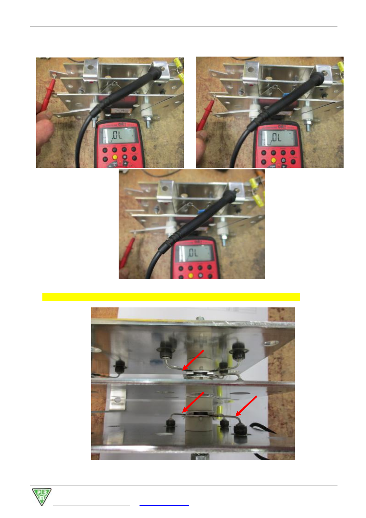
Checking therectifier bridge
The rectifierbridge ismade up ofbutton diodeson aluminiumsheetswhichact asdissipaters.
Toachievedifferentcurrentcapacities,the bridge ismade up ofavariablenumberofdiodes,positioned in
parallelon the sameplate.
Totest operation ofthe RectifierBridge, removeit fromthe charger.
Tocheck the condition ofthesediodes,
usea Digital tester in “Check-Diode” mode :
1)Makesurethata diodevoltage (0,4V÷0,8V) ispresentbypointing the positive testprod on thephases
input fromtransformerand the negative testprod on thepositive outputpole.

TECHNICAL MANUAL "SE"(PBM753) Revisionno. 1dd. 01/02/2017
P.B.M. S.r.l. viaBarella, Z.I. -VIGNOLA(MO )ITALIATel. +39 (059)7705311 Fax+39 (059)7705300
http://www.gruppopbm.ite-mail : pbm@gruppopbm.it file: ManualeSE PBM753 GBrev.1.doc
page 14
2)Makesurethatthereis aninfinitediode bypointing the positivetest prod on positivepoleofbridge output
and negativetest prod on eachphasesinput.
3)Makesurethata diodevoltage (0,4V÷0,8V) ispresentbypointing the positive testprod on the
negative outputpoleofthebridgeand thenegative testprod on thephases input fromtransformer.
TECHNICAL MANUAL "SE"(PBM753) Revisionno. 1dd. 01/02/2017
P.B.M. S.r.l. viaBarella, Z.I. -VIGNOLA(MO )ITALIATel. +39 (059)7705311 Fax+39 (059)7705300
http://www.gruppopbm.ite-mail : pbm@gruppopbm.it file: ManualeSE PBM753 GBrev.1.doc
page 15
4)Makesurethatthereis aninfinitediodevoltage bypointing the positivetestprod on the phasesand
negativetest prod on the negativeoutput ofbridge.
Inaddition totheseinstrumentalchecks, the following empiricalcheckscan be performed:
•Visualchecks toexcludethatthere are blown diodes oranunsolderedrheophore (see photos
following).
TECHNICAL MANUAL "SE"(PBM753) Revisionno. 1dd. 01/02/2017
P.B.M. S.r.l. viaBarella, Z.I. -VIGNOLA(MO )ITALIATel. +39 (059)7705311 Fax+39 (059)7705300
http://www.gruppopbm.ite-mail : pbm@gruppopbm.it file: ManualeSE PBM753 GBrev.1.doc
page 16
•If strong vibrations areheardduring the charging process and the charging process isnotperformed
regularlybecausethe cut-out-switchorthe fusesoperate, itmeansthatthebridgeisin short-circuitand
itneedsreplacing.
•Onthe otherhand itiseasytodiagnosethe openbridge failureon a three-phase charger byoperating
the chargerwithoutconnecting the battery and forcing the powersupplyofthe transformer.Ifan
anomaloustransformervoltage,instead ofano-load voltage,isdetected undertheseconditions,itmeans
that the rectifierbridge isatleastpartiallyopen and needsreplacing.
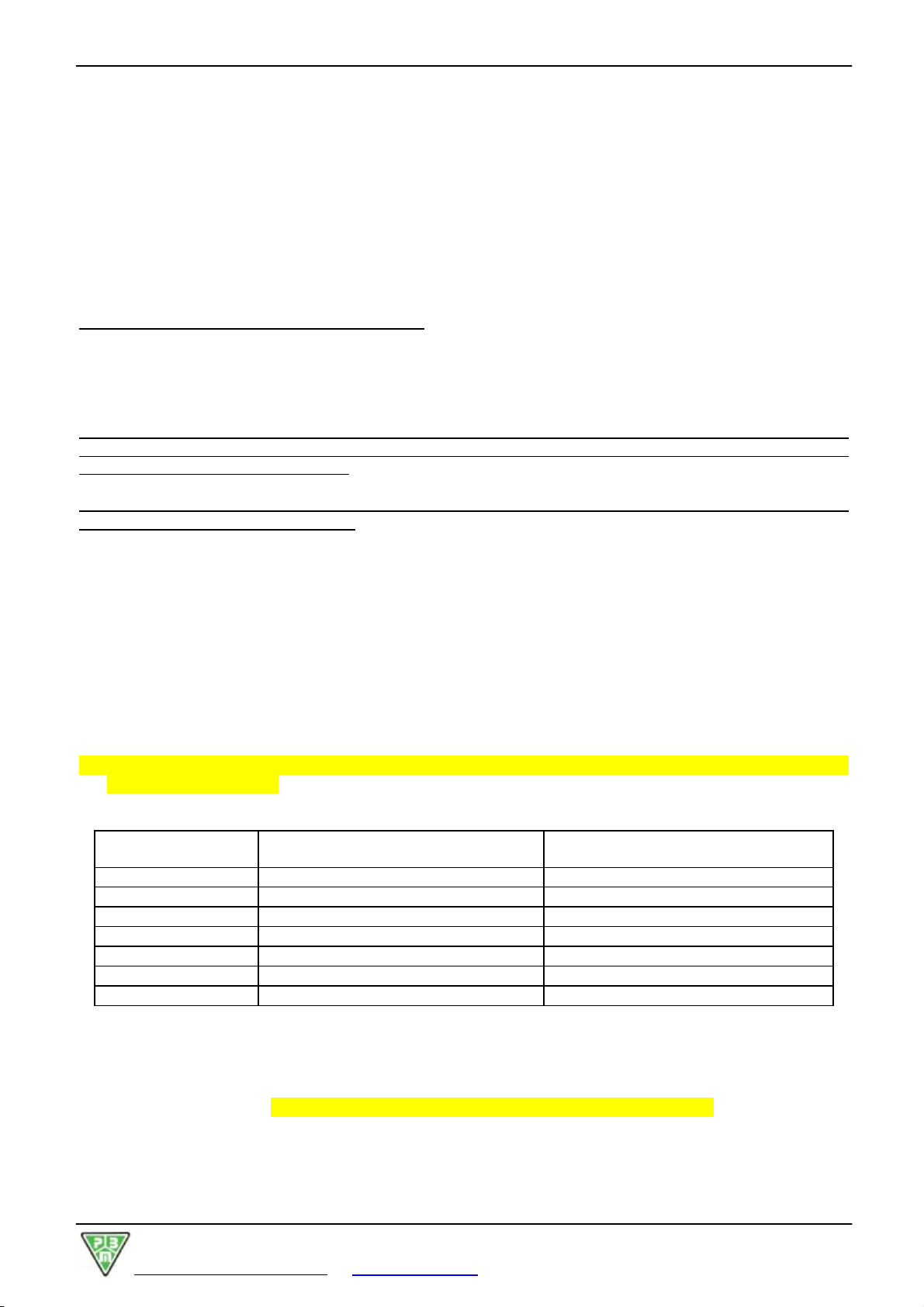
•Asfor single-phase and three-phase battery chargers,the no-loadoutputvoltage correspondstothe
valuescontained inthe following table(provided that transformeriscorrectlypowered).
RATEDBATTERY
VOLTAGE
NO-LOADOUTPUTVOLTAGE(DC)
FORASINGLE-PHASE BATTERY
CHARGER
NO-LOADOUTPUTVOLTAGE(DC)
FORATHREE-PHASE BATTERY
CHARGER
12V 14 ÷15V 18 ÷24V
24V 28 ÷30V 33 ÷38V
36V 42 ÷44V 50 ÷58V
40V 46 ÷48V 60 ÷70V
48V 56 ÷58V 72 ÷80V
72V 85 ÷87V 100 ÷108V
80V 95 ÷98V 110 ÷120V
96V 112 ÷115V 130 ÷150V
CHAPTER11 :MAINTENANCEAND CLEANING
All maintenance and cleaning processes have tobeperformedbyqualified, skilled, and authorised
personnel.
•Sincethe battery chargerisan electricalequipmentwithoutanymoving mechanicalpart, itdoesnotneed
anyspecialmaintenance.
•It ishoweversuggested tocheck,inspect, and clean the charger atleastonce ayear ifitoperatesina
fairly“clean”environment.
•In“hard”conditions, that isindustyand wet environments, checkshavetobe performed more frequently.
The maincheckstobe performed arethe following:
−Placethe charger/soutdoorand removethe closing panel.
−Wearafaceplateand protection devices.Using compressed air,removedustaccumulated inside the
charger.
−Usenon-corrosivedetergentstoremovesludge depositsorotherdirt.
Oncethe chargerhasbeen cleaned, performthe following actions:
−Check the generalcondition ofcomponentsand theirintegrity.
−Replaceoxidized cablesand/orterminals, ifany.
−Useproperspraystoclean electricalcontactson contactors, switches, and commutators.
−Check the tightening ofscrewsand bolts, replacethe rusted items, ifany.
−Performa“dry cleaning”oruseproperspraystoclean electroniccards.
−Check the statusofbothcontroland powerconnectors.Check the “wear” ofpowerconnectorsand
replacethem, ifnecessary.
−Check the condition ofelectricalplugs.
−Onceall the above-mentioned operationshavebeen performed,closepanels,doorsand coversagain,
and placethe charger/sinits/theirposition/sagain.

TECHNICAL MANUAL "SE"(PBM753) Revisionno. 1dd. 01/02/2017
P.B.M. S.r.l. viaBarella, Z.I. -VIGNOLA(MO )ITALIATel. +39 (059)7705311 Fax+39 (059)7705300
http://www.gruppopbm.ite-mail : pbm@gruppopbm.it file: ManualeSE PBM753 GBrev.1.doc
page 17
CHAPTER12:WIRING DIAGRAMS AND PARTSLIST
PARTSLIST“SE” THREE-PHASE see wiring diagramsn° HC01/3
F2 Battery side output fuseNH00 ........ A-T
TL 3-polemainscontactor+NC / 24VAC
PT Thermalcut-out on transformer
CT Terminalboardforvoltage change 230/400 V
CM Terminalboardformainsregulation
TA Auxiliary transformer30VA 0-230-400-420-440V/ 0-24V
TR Three-phasetransformerTAseries
RD Diode rectifierbridge PTSxxx/E
SH1 Shunt 100A/100mVor200A/100mV
P1 ON/OFF green button
PBM753 ElectroniccontrolcardwithmicroprocessorV1.1
F1Fuseforcardpowersupply(5x20 glass 500mAquick)
PARTSLIST“SE” SINGLE-PHASE see wiring diagramsn° HD01/2
F2 Battery side output fuseNH00 ........ A-T
TL 4-poleNO mainscontactorNO / 24VAC
PT Thermalcut-out on transformer
CM Terminalboardformainsregulation
TA Auxiliary transformer30VA 0-220-230-240-250V/ 0-24V
TR Mono phasetransformerC2Aseries
RD Diode rectifierbridge PMSxxx
SH1 Shunt 100A/100mVo200A/100mV
P1 ON/OFF green button
PBM753 ElectroniccontrolcardwithmicroprocessorV1.1
F1 Fuseforcardpowersupply(5x20 glass 500mAquick)


Table of contents
Other P.B.M. Batteries Charger manuals


