Eltek MultiCharger 1500 Manual

Description and Operating Instructions
2280073 Rev.1
MultiCharger 1500
12V/100A...24V/50A
12V/100A Lithium-ion and Lead-acid Batteries
24V/50A Lead-acid Batteries
Read operating instructions carefully before use!

2280073 Rev.1 Page 2
Imprint
MultiCharger 1500
EVD .: 811-0206-0
Doc-No.: 2280073.01
ID-code: 0109
The complete documentation is part of the delivery and must remain with the charger unit.
Information provided in this document is subject to the right of change without prior notice and
does not represent properties which are guaranteed by Eltek.
This document or parts of it may not be reproduced, copied or made accessible to third parties
without prior written consent from ELTEK.

2280073 Rev.1 Page 3
Contents Page
Use 6
1.1 Competent person 6
1.2 Normal use 6
1.3 Misuse 6
Fundamental safety instructions 7
2.1 Safety symbols used 7
2.2 General safety instructions 8
Construction of the charger unit 13
3.1 General mode of operation 13
3.2 Connections 14
3.2.1 9-pole SUB-D socket 15
3.2.2 15-pole SUB-D socket 15
3.3 Displays and operating controls 16
3.3.1 Control button 1 (on/off) 16
3.3.2 Control button 2 (start/stop) 16
3.3.3 Control button 3 (enter) 16
3.3.4 Control button 4 (up) 16
3.3.5 Control button 5 (down) 16
3.3.6 USB interface 17
3.3.7 LED, green, yellow, red 17
3.3.8 LC Display 17
Setting of cable (wire) resistance 18
4.1 Standard battery-connecting cables 18
4.2 Calculation of cable resistance 18
Charging process 19
5.1 Positioning of the MultiCharger 19
5.2 Battery preparation 19
5.3 Charging of a battery installed in the vehicle 19
5.4 Charging of a battery outside the vehicle 20
Operating modes/charging mode (permanent settings) 21
6.1 Setting of operating modes 21
6.2 Charging mode for lead-acid batteries (Charging Pb) 21
6.3 Charging AGM batteries 22
6.4 Charging gel batteries 22
6.5 Charging motorcycle batteries 22
6.6 Charging mode for 12 V lithium-ion batteries (Charging LIO) 23
6.7 Overview of applicable voltage ranges 23
6.7.1 Output voltage in battery charging mode 24
6.7.2 Output current in battery charging mode 24
6.8 EPS mode 25
6.9 EPS autostart mode 25

2280073 Rev.1 Page 4
Page
Operating modes (temporary settings) 26
7.1 Setting of operating modes 26
7.2 Charging mode for lithium-ion batteries, temporary 26
7.3 Charging mode for lead-acid batteries, temporary 26
7.4 Refresh (if disconnecting switch of the lithium-ion battery is open) 27
7.5 Shutdown (only possible in the charging mode for lithium-ion batteries) 27
Internal monitoring 28
8.1 Mains power monitoring 28
8.2 Monitoring of intermediate-circuit voltage 28
8.3 Output overvoltage 28
8.4 Output undervoltage 28
8.5 Output overcurrent 29
8.6 Temperature monitoring 29
8.7 Relay monitoring 29
External monitoring 30
9.1 Short circuit 30
9.2 Reverse polarity 30
9.3 Faulty battery 30
9.4 Clamp contact 30
9.5 Return voltage 30
9.6 Return voltage with reversed polarity 31
9.7 Shutdown error 31
9.8 Refresh error 31
Service menu 32
10.1 Setting of operating modes 36
10.1.1 Charging Pb 36
10.1.2 Charging LIO 36
10.1.3 EPS 12V mode 36
10.1.4 EPS 24V mode 36
10.1.5 EPS autostart mode (Auto. start EPS) 36
10.2 Activate 24V mode 37
10.2.1 24V mode on/off 37
10.3 Set voltage 37
10.3.1 Set 12V Pb trickle voltage 37
10.3.2 Set 12V LIO trickle voltage 37
10.3.3 Set 24V trickle voltage 37
10.3.4 Set 12V Pb charging voltage 38
10.3.5 Set 12V LIO charging voltage 38
10.3.6 Set 24V charging voltage 38
10.3.7 Set U-Shutdown 38
10.3.8 Set U-Refresh 38
10.3.9 Set 12V EPS voltage 38
10.3.10 Set 24V EPS voltage 38

2280073 Rev.1 Page 5
Page
10.4 Set voltage limits 39
10.4.1 Set Ua max. 12V 39
10.4.2 Set Ua min. 12V 39
10.4.3 Set Ua max. 24V 39
10.4.4 Set Ua min. 24V 39
10.5 Output-current limits (I-limits) 40
10.5.1 Set I-limit CHRG12V 40
10.5.2 Set I-limit CHRG24V 40
10.5.3 Set I-limit EPS 12V 40
10.5.4 Set I-limit EPS 24V 40
10.6 Set process times 41
10.6.1 Set switch back time 41
10.6.2 Set maximum charging time 41
10.6.3 Set I-limit 2 41
10.7 Set cable (wire) resistance 41
10.8 Turn on/off autostart 42
10.8.1 Autostart now enabled and Autostart now disabled 42
10.9 Error log 42
10.9.1 Error 0 - 9 42
Derating 43
Factory (default) settings 44
Select language 44
Technical data 45
Appendix A Status and error descriptions 47

Use
Use
1.1 Competent person
A person is regarded as competent person if he/she is assigned as instructed to perform
particular works on or with the MultiCharger.
1.2 Normal use
The MultiCharger 1500 (referred to below as MC1500) is intended for charging vehicle batteries:
lead-acid batteries with a nominal voltage of 12 V or 24 V
lithium-ion batteries with a nominal voltage of 12 V
external power supply for motor vehicles
1.3 Misuse
charging of batteries which have a different nominal voltage
charging of frozen batteries
connection of non-rechargeable batteries
connection of dry batteries
any other use than described above.
Fundamental safety instructions
2280073 Rev.1 Page 7
Fundamental safety instructions
The following fundamental safety instructions are to be understood as supplement to applicable
national occupational safety regulations. This means that, next to these fundamental safety
instructions, the applicable national occupational safety regulations shall be observed in any
case.
The charger unit is not intended to be used by persons (including children) with limited physical,
sensory or cognitive abilities or with lack of experience and knowledge unless they are
supervised. Children shall not be allowed to play with the charger unit.
2.1 Safety symbols used
Danger!
This symbol indicates the presence of essential health hazards for
persons.
In case of possible mortal danger, this will be separately indicated by
the phrase „Danger to life“.
Danger!
This symbol indicates the presence of electrical health hazards for
persons which are caused by electrical voltages.
In case of possible mortal danger, this will be separately indicated by
the phrase „Danger to life“.
Danger!
This symbol indicates the presence of hazards for the system, the
material or environment.
In case of possible mortal danger, this will be separately indicated by
the phrase „Danger to life“.

Fundamental safety instructions
2280073 Rev.1 Page 8
2.2 General safety instructions
In order to charge a battery outside of the vehicle, connect the positive (plus) and the negative
(minus) cables in accordance with polarity (see section 5).
For a battery installed in the vehicle, first connect the red charging cable of the charger to the
positive terminal (+) of the battery (not connected with the chassis) according to the polarity
indications and then the black charging cable to the negative terminal (–) of the battery. Do not
connect to carburettor or fuel lines. After charging, disconnect the negative cable (chassis-
connected cable) first (see section 5).
Danger!
Serious or fatal injuries
Explanation:
Disconnecting the battery during charging can result in temporary
sparking
Avoidance measures:
Terminate charging by using control button 2 (start/stop) before
disconnecting the battery
Danger!
Serious or fatal injuries
Explanation:
An attempt to charge non-rechargeable batteries causes explosion risk
Avoidance measures:
Connect rechargeable batteries only
Danger!
Serious or fatal injuries
Explanation:
Risk of explosion when battery is overloaded
Avoidance measures:
No overcharging of battery –see instructions for use
Danger!
Serious or fatal injuries
Explanation:
During charging, oxyhydrogen gas is usually generated. There is a risk
of explosion!
Avoidance measures:
Read the operating instructions before using the charger and follow the
instructions closely.
Operate the charger only in well ventilated areas.
Do not smoke in the vicinity of the battery.
Avoid fire and flying sparks.
Fundamental safety instructions
2280073 Rev.1 Page 9
Danger!
Serious or fatal injuries and/or damage to the charger unit
Explanation:
During operation in moving vehicles, equipment is not sufficiently
safeguarded. It is possible that cables are torn off (spark generation) or
that the battery tips over (damaging)
Avoidance measures:
Do not operate charger unit in moving vehicles
Danger!
Occurrence of secondary failures as a result of problems during
charging
Explanation:
Problems occurring during charging can result in leakage of acid and,
when personal precautions are inadequate or not observed, in
secondary failures.
Avoidance measures:
Somebody should be within voice range in order to be able to provide
or organize assistance.
Keep plenty of water and soap on hand in case acid comes in contact
of with skin or clothes.
Wear protective clothes incl. safety goggles and avoid touching the
eyes with your hands.
However, if battery acid comes into contact with skin or clothes, rinse
immediately; in case of contact with eyes, intensively rinse at least for
10 min with cold water and then consult an ophthalmologist
Danger!
Serious or fatal injuries
Explanation:
metal items between the battery terminals can result in a risk of short
circuit or explosion as well as in severe burns
Avoidance measures:
Cover non-isolated contacts if possible.
Take care when handling metal tools.
Take off rings, necklaces, bracelets, watches
Danger!
Risk of injury due to electric shock
Explanation:
risk of harm to people due to electric shock in case of failure when
unearthed sockets and power cables are used
Avoidance measures:
Ensure that the power supply cord is appropriately earthed!

Fundamental safety instructions
2280073 Rev.1 Page 10
Fundamental safety instructions
2280073 Rev.1 Page 11
Danger!
Risk of injury due to electric shock
Explanation:
There is a risk of electric shock when touching non-isolated parts of the
contacts and non-isolated battery clamps.
Avoidance measures:
Avoid touching any non-isolated parts of the contacts and non-isolated
battery clamps.
Danger!
Risk of injury due to electric shock
Explanation:
The use of improper extension cords can result in damages and electric
shock.
Avoidance measures:
Use extension cords only if absolutely necessary. Use only suitable
cables. Pay attention to:
a) same number, size and shape of the pins in the plug
b) connectors at the charger unit
c) proper wiring and sound electric condition of the extension cord
d) correct cross-section of the cable
Danger!
Risk of injury due to electric shock
Explanation:
There is a risk of electric shock when using defective cables and leads
especially in case of power cords.
Avoidance measures:
Defective leads and cables have to be replaced immediately.
Danger!
Risk of injury due to electric shock
Explanation:
There is a risk of electric shock when using equipment which has been
exposed to severe mechanical stresses (shocks, dropped equipment,
visible external damage).
Avoidance measures:
If the charger unit has experienced severe mechanical impacts, it has
to be shipped to a qualified service company for inspection/repair.
Abstain from self-repair.

Fundamental safety instructions
2280073 Rev.1 Page 12
Danger!
Risk of injury due to electric shock
Explanation:
There is a risk of electric shock if actions (cleaning, maintenance,
repair) are executed on the charger unit while the power cord is
connected.
Avoidance measures:
Disconnect leads before working on the charger unit.
Warning!
Equipment damage or failure possible!
Explanation:
The charger unit might be damaged due to constructional modifications.
Avoidance measures:
Do not modify the construction of the Multicharger! In the case of fixing
to accessories, the instructions supplied with said accessories have to
be observed.
Warning!
Equipment damage or failure possible!
Explanation:
Outdoor storage and operation of the charger unit in case of rain or
snow can lead to equipment damage.
Avoidance measures:
Do not expose the MultiCharger to rain or snow.
Warning!
Equipment damage or failure possible!
Explanation:
Pulling at the cable can result in damage of the corresponding lead.
Avoidance measures:
Always grip the plug of the cables/leads in question (in the case of
power cord, first release the strain relief at the charger unit).
END OF SAFETY INSTRUCTIONS

Construction of the charger unit
2280073 Rev.1 Page 13
Construction of the charger unit
3.1 General mode of operation
The MC1500 is used for charging motor vehicle batteries and can also be used as an external
power supply for vehicles. The charger unit is designed for the usage in 12V systems with
lithium-ion and lead-acid batteries as well as in 24V systems with lead-acid batteries. The power
output is 1500W, which is sufficient to charge all common vehicle batteries.
The MC1500 is fed from the mains supply and transforms the connected alternating current
voltage into direct current voltage. The power section is fitted with an isolating transformer to
ensure that the output voltage is electrically isolated from the mains supply.
For protection, input and output cut-outs are built into the MC1500. Additionally, a current limiter
prevents the MC1500 from getting damaged by overload.
The MC1500 is designed as a bench unit, which is cooled by the free flow of air from the base
to the top. Therefore, make sure that the MC1500 remains uncovered. All displays and
operating controls are located on the front of the MC1500.
Construction of the charger unit
2280073 Rev.1 Page 14
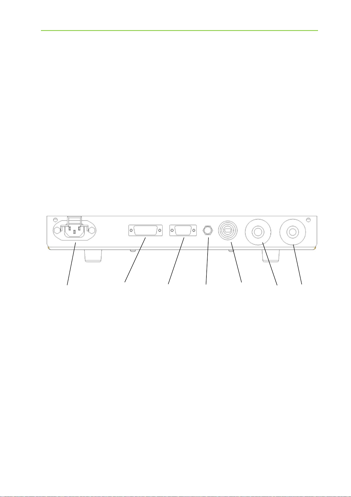
3.2 Connections
All connections of the MC1500 are on the front.
Mains voltage is connected to the MC1500 through an inlet connector for non-heating
appliances.
3 potential-free relay contacts which signal various states of the MC1500 as well as a hardware
contact "Remote On/Off" can be connected through a 15-pole SUB-D socket.
To connect a signal light, a 9-pole SUB-D socket is used.
The signal light (green/yellow/red) signals various states of the MC1500.
A M8 plug-in connector (three-pole socket) can be connected to a sensor cable (only for special
applications).
A Mini-USB socket is used for configuration via PC and the software WinCharge. Software
updates can also be carried out through this interface.
Battery connection is made by means of bayonet connectors. The bayonet connectors are
connected with an corresponding charging cable with battery clamps.
Mains connection 15-pole 9-pole sensor Mini USB L- L+
SUB-D SUB-D cable socket Battery
socket socket connections

Construction of the charger unit
2280073 Rev.1 Page 15
3.2.19-pole SUB-D socket
A 9-pole SUB-D socket on the front side of the charger unit is used to connect a signal light.
The signal light (green/yellow/blue/red) indicates the following states of the MultiCharger:
State
Signal light –LED colours
red
yellow
grün
blau
MultiCharger off, standby, remote OFF,
mains OFF
off
off
off
off
MultiCharger on and trickle charging,
battery fully charged or second current limit
reached
off
off
on
off
MultiCharger on and charging in the Pb or
EPS mode
off
on
off
off
MultiCharger not contacted
off
flashing
off
off
MultiCharger on and charging in the
lithium-ion mode
off
off
off
on
Device error
on
off
off
off
Operating error (e.g. reversed polarity,
short circuit)
flashing
off
off
off
Power-up (charging start with disconnecting
switch in open position)
power-down (shutdown)
off
off
flashing
off
3.2.215-pole SUB-D socket
A 15-pole SUB-D socket provides 3 potential-free relay contacts which signal the following
states of the MC1500:
State
Relay 3
Relay 2
Relay 1
MultiCharger off, standby, remote OFF,
mains OFF
0
0
0
MultiCharger on and trickle charging, battery
fully charged or second current limit reached
0
0
1
MultiCharger on and charging in the Pb or
EPS mode
0
1
0
MultiCharger not contacted
0
1
1
MultiCharger on and charging in the
lithium-ion mode
1
0
0
Device error
1
0
1
Operating error (e.g. reversed polarity,
short circuit)
1
1
0
Power-up (charging start with disconnecting
switch in open position)
power-down (shutdown)
1
1
1
1: relay energized, 0: relay released
Construction of the charger unit
2280073 Rev.1 Page 16
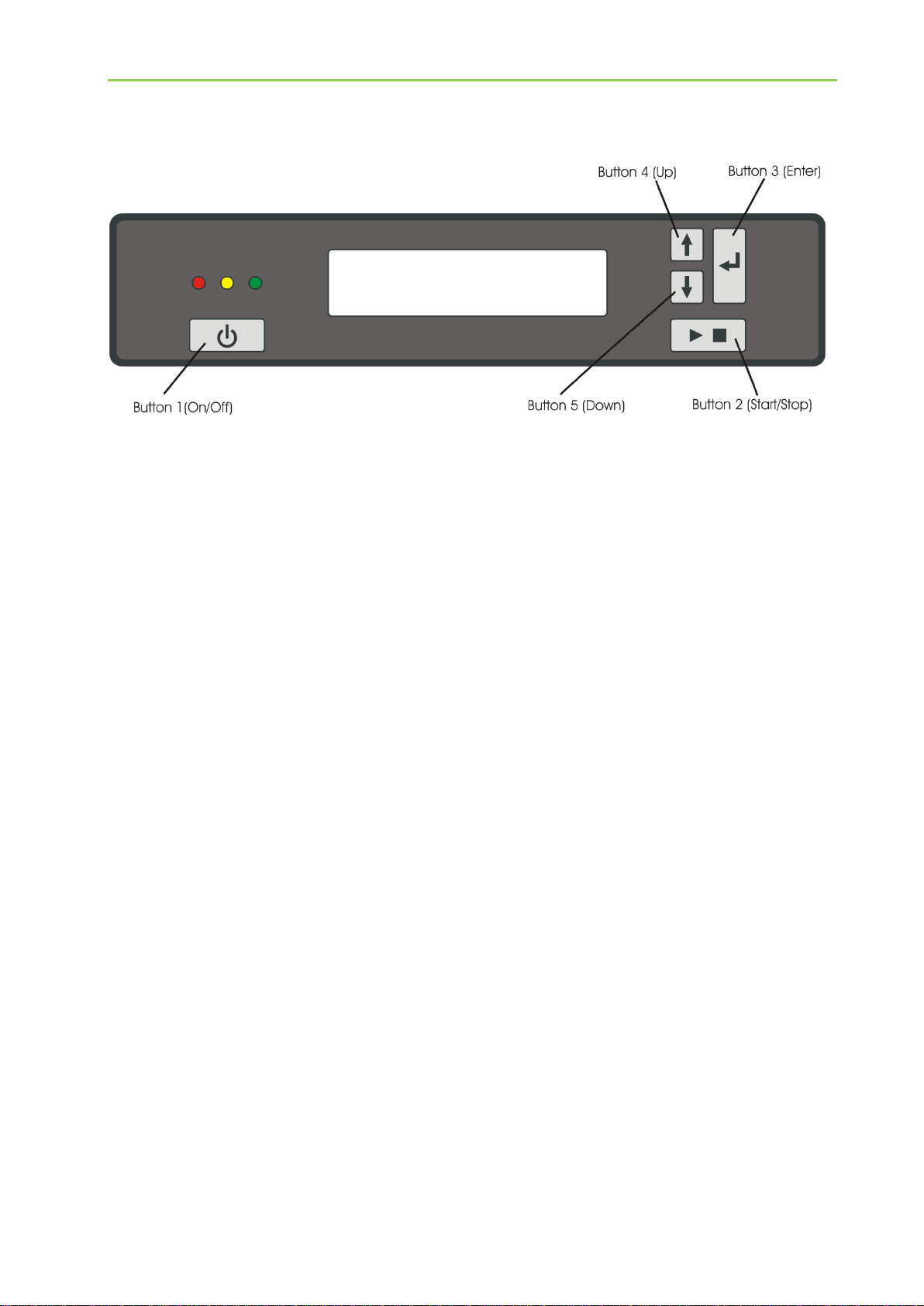
3.3 Displays and operating controls
3.3.1Control button 1 (on/off)
Control button 1 is used to switch the M1500 on and off. If the connected supply voltage is over
90V, pressing button 1 switches the MultiCharger on and makes it ready for use.
Furthermore, pressing button 1 is required to deactivate the interlock after a fault-induced shut-
down.
3.3.2Control button 2 (start/stop)
Control button 2 is used to start or stop the charging process or the EPS operation.
3.3.3Control button 3 (enter)
Control button 3 is used as a button to confirm entries and for system navigation.
3.3.4Control button 4 (up)
Control button 4 is a navigation button.
3.3.5Control button 5 (down)
Control button 5 is a navigation button.
2280073 Rev.1 Page 17
3.3.6USB interface
A Mini USB socket is fitted on the front side of the charger unit which can be used to connect a
laptop or PC.
The MC1500 can be configured through this interface and software updates can be carried out.
To configure or alter the device software (Firmware Update), the software WinCharge is
required. Detailed information about this can be found in the description of the PC software
WinCharge.
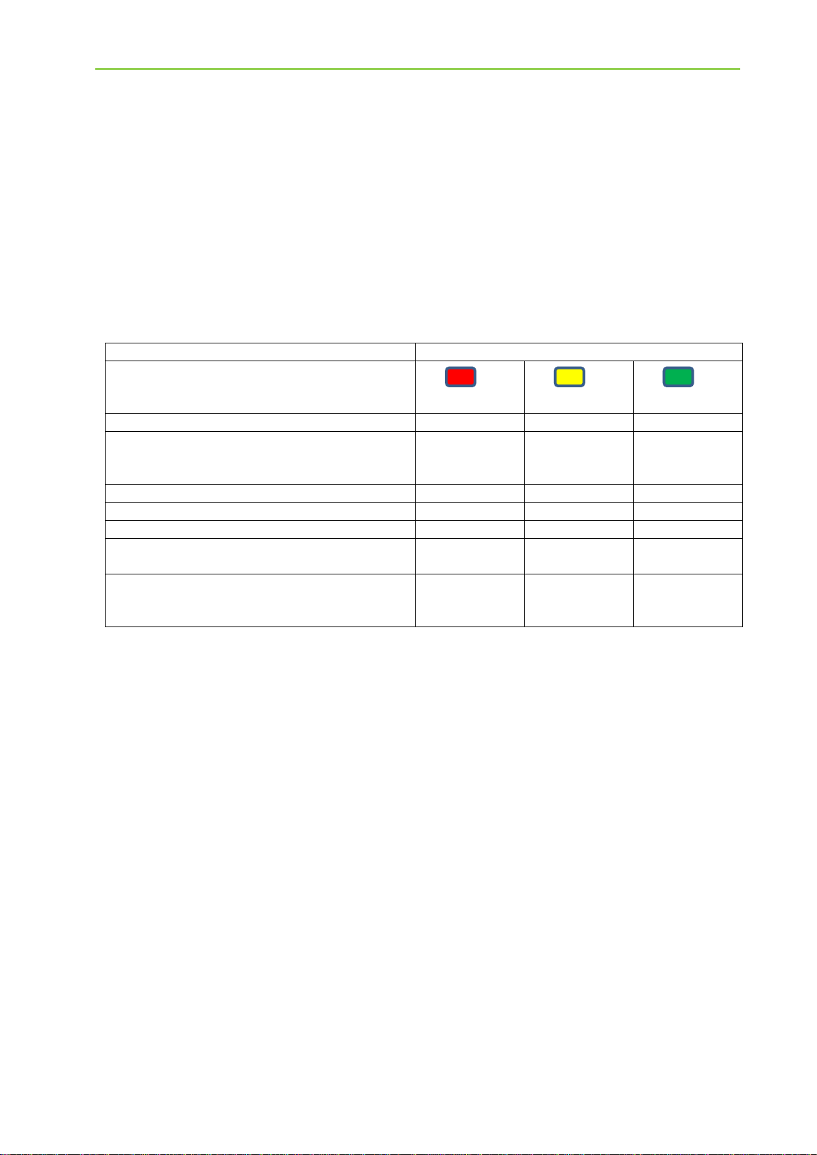
3.3.7LED, green, yellow, red
The LEDs (green/yellow/red) on the display signal the following states of the MultiCharger:
State
LED colour
red
yellow
green
MultiCharger off, standby
off
off
off
MultiCharger on and trickle charging,
battery fully charged or second current limit
reached
off
off
on
MultiCharger on and in charging mode
off
an
off
MultiCharger not contacted
off
flashing
off
Device error
on
off
off
Operating error (e.g. reversed polarity,
short circuit)
flashing
off
off
Power-up (charging start with disconnecting
switch in open position)
power-down (shutdown)
off
off
flashing
3.3.8LC Display
The LC display of the MC1500 has two lines and can display 16 characters per line.
The current values of output voltage and output current are displayed on the top line. The
bottom line acts as a status display showing in plain text the operating state and details of any
faults that occur (see Appendix A).
The LCD is illuminated and, therefore, can be easily read both in the dark and in direct sunlight.

Setting of cable (wire) resistance
2280073 Rev.1 Page 18
Setting of cable (wire) resistance
The new software version of the MC1500 includes a cable (resistance) compensation to
compensate for voltage drop at the connecting cables of the battery.
4.1 Standard battery-connecting cables
In the delivery condition, a cable resistance of 15 mΩ is preset. This applies for a
5 meter/16 mm² battery connecting cable. If a different cable length or a different conductor
cross-section is used, the cable resistance has to be adjusted in the service menu
(see section 10.7).
Cable-resistance values of the battery’s standard connecting cable:
Cable length/conductor cross-section: cable resistance:
5m/16mm² 15mΩ
7m/16mm² 20mΩ
4.2 Calculation of cable resistance
The cable resistance is calculated according to the following equation:
cable resistance = 2 ∗ 𝑙
ĸ ∗ 𝐴 + 𝑅_transfer
Example of a 5m battery connecting cable:
Cable length (𝑙): 5m
Electrical conductivity of copper (ĸ): 56m/(Ωmm²)
Conductor cross-section (𝐴): 16mm²
Transfer (contact) resistance = 𝑅_transfer: 4mΩ (transfer resistance of clamps and screw
connections)
Calculation of cable resistance ((2 5) / (56 16)) 0.004
0.01516Ω
15mΩ

Charging process
2280073 Rev.1 Page 19
Charging process
Carefully read and observe the safety instructions given in section 2 as well as the instructions
of the respective battery manufacturer concerning safety and charging current.
5.1 Positioning of the MultiCharger
a) Position the charger unit as far away from the battery as possible, make use of the entire
cable length of the connected charging cable and check for (static) stability
b) Do not place the MultiCharger directly on top of the battery
c) Avoid dripping of acid onto the charger unit.
d) Do not place the battery on top of the charger unit
5.2 Battery preparation
a) For charging, remove the battery from the vehicle if possible. Before charging, switch off
all consumers to avoid any arcs. Disconnect the grounded terminal first.
Procced with 5.4; if the battery cannot be removed, proceed with 5.3.
b) Clean battery terminals and protect eyes against rust particles which might be blown up.
c) In the case of lead-acid batteries (WET), check the acid level and add distilled water as
necessary. This removes excessive gas from cells. Maximum level shall not be
exceeded!
In case of a battery without cell caps, carefully follow the manufacturer's charging
instructions.
5.3 Charging of a battery installed in the vehicle
a) Connect to the mains, connect charging cable to the charger unit; arrange mains and
charging cables so that they cannot be damaged by the bonnet, door or moving parts.
b) Switch on the charger unit and set the desired charging mode (see section 6).
c) Stay clear of fan blades, belts, pulleys, and other moving parts that can cause injuries.
d) Check polarity of battery terminals. The diameter of the positive battery terminal (POS,
P, ) is usually larger than that of the negative terminal (NEG, N, ).
e) Determine which battery terminal is grounded (connected to the chassis).
If the negative terminal is grounded (as in most vehicles), proceed with (f). If the positive
terminal is grounded, proceed with (f). The charging points present in the vehicle should
be used.
f) For negative-grounded vehicle, connect the POSITIVE (RED) clamp to the POSITIVE
(POS, P, ) terminal of the battery; connect the NEGATIVE (BLACK) clamp to the chassis,
engine block or frame (not to the carburettor, fuel lines, or sheet-metal body parts) as far
away from the battery as possible. See section 6 for charging mode.
g) For positive-grounded vehicle, connect the NEGATIVE (BLACK) clamp to the NEGATIVE
(NEG, N, -) battery terminal. Connect the POSITIVE (RED) clamp to the chassis, engine
block or frame (not to the carburettor, fuel lines, or sheet-metal body parts) as far away
from the battery as possible. See section 6 for charging mode.
h) Interrupt/terminate the charging process by pressing control button 2 (start/stop).
i) Disconnection of charger unit –pull mains plug, disconnect clamp from chassis and the
other clamp from the battery terminal.
WARNING! Temporary sparking can occur when disconnecting the cable before charging has
been terminated without the button 2 (start / stop) to operate.

Charging process
2280073 Rev.1 Page 20
5.4 Charging of a battery outside the vehicle
a) Connect to the power supply and connect charging cable to the charger unit.
b) Check polarity of battery terminals. The diameter of the positive battery terminal
(POS, P, ) is usually larger than that of the negative terminal (NEG, N, ).
c) First, connect the NEGATIVE (BLACK) clamp of the charging cable supplied with the
charger to the NEGATIVE (NEG, N, -) terminal.
d) Connect the POSITIVE (RED) clamp to the POSITIVE (POS, P, ) battery terminal.
e) See section 6 for charging mode.
f) Interrupt/terminate the charging process by pressing control button 2 (start/stop).
g) Disconnect cable connections in reverse order.
Other manuals for MultiCharger 1500
1
Table of contents
Other Eltek Batteries Charger manuals

Popular Batteries Charger manuals by other brands

Premium Supply
Premium Supply RoaDCharger 20 Amp 7 Way installation manual

VDC Electronics
VDC Electronics BatteryMINDer Quick start instructions

Panasonic
Panasonic BQ-CC51E operating instructions

Powercore
Powercore CHARGECORE AC Wallbox Series manual

Hama
Hama 14094 Operating instruction

Dok
Dok CR08 user guide


