eltherm ELK-MI-AY825 User manual

eltherm GmbH
Ernst-Heinkel-Str. 6-10
57299 Burbach
T.: +49 2736 4413-0
F.: +49 2736 4413-50
86500043
QAA – 021-Ex
Operating Manual Heat Tracing System
ELK-MI-AY825 / ELK-MI-VA
In Hazardous Locations (Ex)
Author
Peter Schmidt
Revision 3
0080083
03.02.2020
Operating Manual
Mineral-Insulated Heat Tracing System
ELK-MI-AY825 / ELK-MI-VA in
Hazardous Locations (Ex)

86500043
Operating Manual Heat Tracing System
ELK-MI-AY825 / ELK-MI-VA
In Hazardous Locations (Ex)
Author
Peter Schmidt
Revision 3
03.02.2020
Page 2 of 21
Inhalt
2. System Components ...................................................................................................... 3
2.1 The Single Core Heating Systems comprise the following components:............................ 3
2.2 The Twin Core Heating Systems comprise the following components:.............................. 4
3. Technical Data ............................................................................................................... 4
4. Available Resistances ..................................................................................................... 5
4.1 ELK-MI-VA and VA-T ............................................................................................................ 5
4.2 ELK-MI-AY825 ...................................................................................................................... 7
4.3 ELK-MI-AY825 T ................................................................................................................... 8
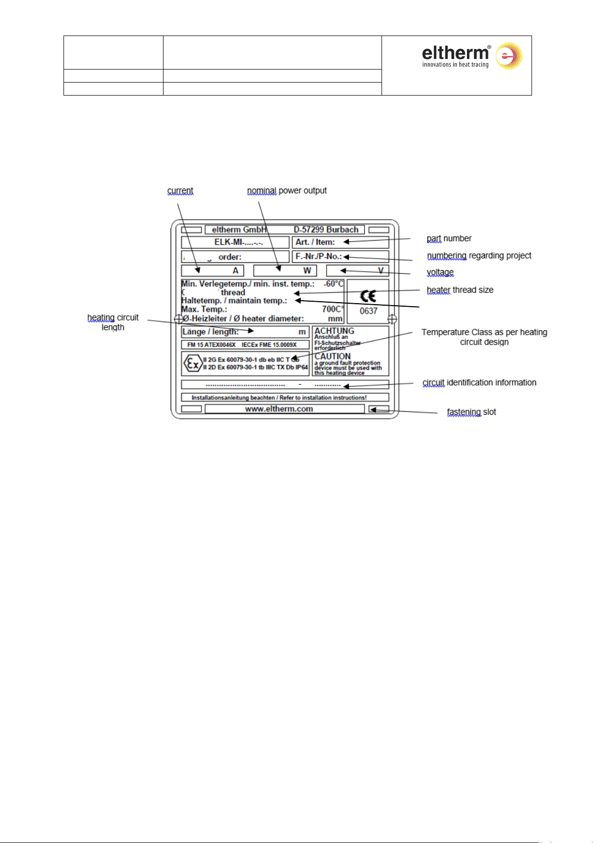
5. Marking ......................................................................................................................... 9
6. Restrictions on thickness and material of thermal insulation........................................... 9
7. Heating Circuit Design .................................................................................................... 9
8. Location of temperature sensors .................................................................................... 9
8.1 Temperature controllers ..................................................................................................... 9
8.2 Temperature limiters......................................................................................................... 10
9. Summary of Conditions of Safe Use as per Type Approval Certificate............................. 11
10. Installation of the Heat Tracing System ELK-MI-**** Ex................................................. 12
10.1 Application......................................................................................................................... 12
10.2 Receipt of Goods ............................................................................................................... 12
10.3 Storage .............................................................................................................................. 12
10.4 Length of Heating Circuit................................................................................................... 12
10.5 Protective Measures.......................................................................................................... 13
10.6 Heater Installation............................................................................................................. 13
10.7 Test and Commissioning.................................................................................................... 15
10.8 Operation and Maintenance: ............................................................................................ 16
11.Installation of ELK-MI Trace Heaters ............................................................................. 17
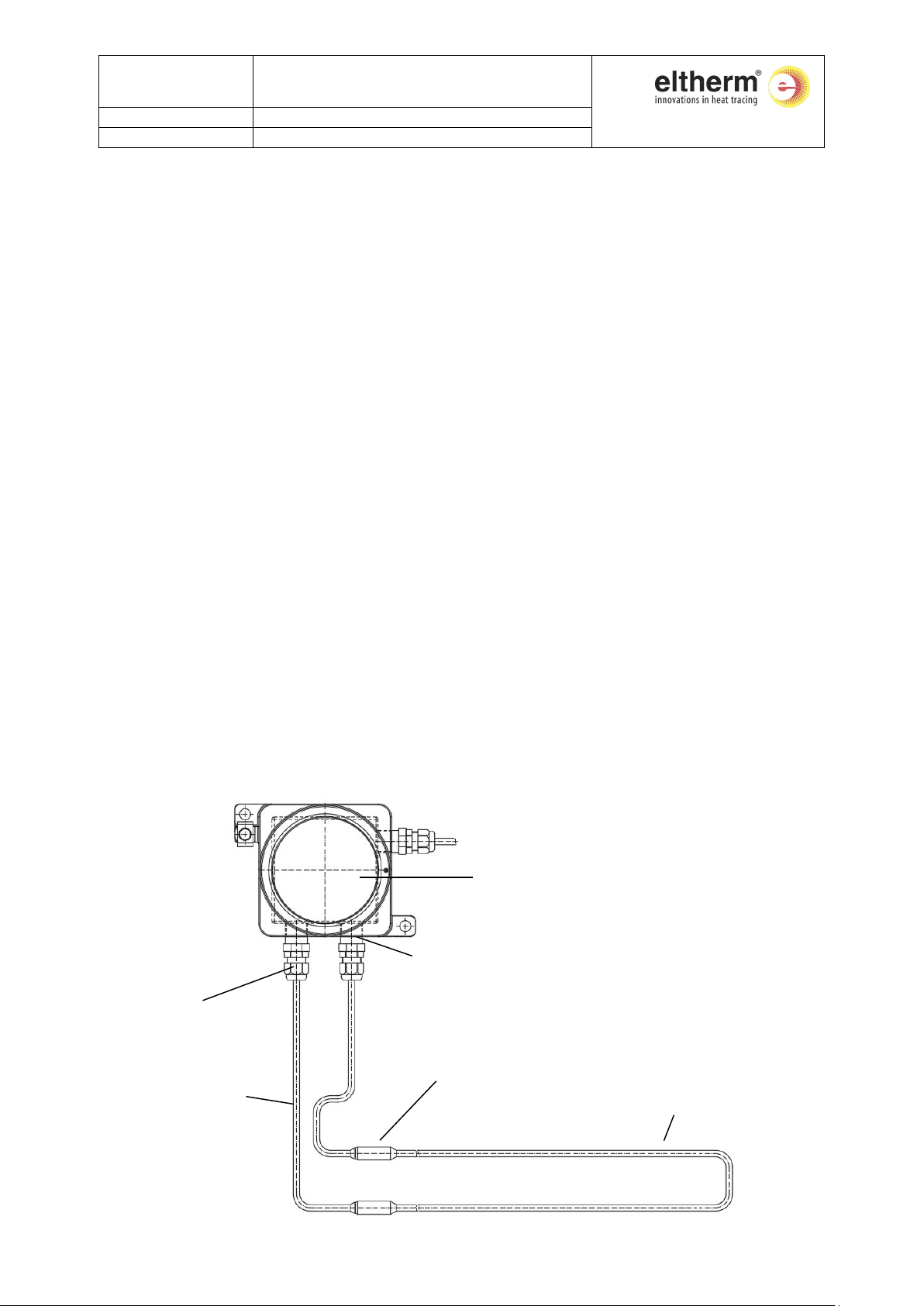
11.1 Typical Installation of Mineral-Insulated Trace Heaters on Pipes..................................... 17
11.2 Typical Installation of Mineral-Insulated Trace Heater on Flanges................................... 18
11.3 Typical Installation of Mineral-Insulated Trace Heater on Elbows ................................... 18
11.4 Typical Installation of Mineral-Insulated Trace Heater on Valves .................................... 19
11.5 Typical Installation of Mineral-Insulated Trace Heater on Pumps.................................... 19
12. Installation of Gland..................................................................................................... 20
12.1 Design and Technical Data ................................................................................................ 20
12.2 Installation......................................................................................................................... 20
12.3 Operation and maintenance ............................................................................................. 21

86500043
Operating Manual Heat Tracing System
ELK-MI-AY825 / ELK-MI-VA
In Hazardous Locations (Ex)
Author
Peter Schmidt
Revision 3
03.02.2020
Page 3 of 21
1. Einsatzbereich
The Heat Tracing System ELK-MI-**** Ex is suitable for industrial use on piping, vessels,
instrumentation and related equipment in areas where combustible gases or dust may be
present. For details please refer to the attached type plate.
The system is based on series and twin heaters and is to be operated in controlled or stabilized
design as per IEC EN 60079-30-1 and -2. All electrical connections must be made to a suitable
junction box approved for Hazardous Areas or connected outside the Hazardous Area.
Furthermore, the heat tracing installation must meet the requirements of IEC EN 60079-14.
Installation is to be done by eltherm or by a specialist contractor for installation of electrical
systems in hazardous areas.
The T ratings for heating circuits are determined by eltherm (this includes confirmations of T
ratings made by third parties).
2. System Components
The Heat Tracing System ELK-MI-**** Ex comes prefabricated and ready for installation.
2.1 The Single Core Heating Systems comprise the following components:
•1 (each) Mineral insulated single core trace heater as per table 1, 2 and 3
•2 (each) Laser welded splices
•2 (each) Mineral insulated cold leads
•2 (each) Potted end seals with pigtails
•2 (each) Glands
potted end seal and pigtails
1 x phase 2.5 mm²
1 x earth 2.5 mm²
eltherm gland threaded
M20x1.5 , M25x1.5 , ½” NPT
or ¾” NPT
integral mineral
insulated cold lead, sheath
material same as heater
ELAK-Ex-3d or other IECEx / ATEX
approved junction box suitable for
area rating (separate)
integral mineral insulated
splice, internally and
externally laser welded,
material same as heater
sheath
mineral insulated single core
heater, sheath stainless
steel, alloy 825 or alloy 600

86500043
Operating Manual Heat Tracing System
ELK-MI-AY825 / ELK-MI-VA
In Hazardous Locations (Ex)
Author
Peter Schmidt
Revision 3
03.02.2020
Page 4 of 21
2.2 The Twin Core Heating Systems comprise the following components:
•1 (each) Mineral insulated twin core trace heater as per table 1, 2 and 4
•1 (each) Laser welded splice
•1 (each) Mineral insulated cold lead
•1 (each) Potted end seal with pigtails
•1 (each) Gland
•1 (each) Laser welded end termination
3. Technical Data
Sheath material VA / VA-T: stainless steel 1.4541 (AISI 321)
AY600 / AY600-T: Mat. 2.4816 (Alloy 600)
AY825 / AY825-T: Mat. 2.4858 (Alloy 825)
Gland material stainless steel 1.4404 (AISI 316L)
Min. bend radius 6 x cable diameter (see type plate or Tables 1, 2, 3 and 4 for
details)
Max. voltage 600VAC (AY600 / VA / AY825 / AY825-T; refer to type plate)
500VAC (AY600; refer to type plate)
400VAC (AY600-T / VA-T; refer to type plate)
300VAC (AY825-T; refer to type plate)
Max. exposure temp. 700°C (AY825 / AY825-T)
565°C
80°C (potted end seals)
Max. operating temp. refer to type plate
Min. installation temp. -60°C
Min. start up temp. -60°C
integral mineral insulated end
termination, material same as heater
sheath, internally and externally laser
welded
eltherm gland threaded M20x1.5,
M25x1.5 , ½” NPT or ¾” NPT
potted end seal and pigtails
(2 x phase [cross section same as cold lead
conductor], 1 x earth 1.5 mm²)
integral mineral insulated cold lead
(cross section 2.0, 2.5, 3.3 or 5.0 mm²),
sheath material same as heater
integral mineral insulated
splice, material same as heater
sheath, internally and
externally laser welded
mineral insulated twin core heater, sheath
stainless steel, alloy 825 or alloy 600
ELAK-Ex-3d or other IECEx / ATEX
approved junction box suitable for
area rating (separate)

86500043
Operating Manual Heat Tracing System
ELK-MI-AY825 / ELK-MI-VA
In Hazardous Locations (Ex)
Author
Peter Schmidt
Revision 3
03.02.2020
Page 5 of 21
4. Available Resistances
4.1 ELK-MI-VA and VA-T
Table 1: Available resistances and bend radii ELK-MI-VA and ELK-MI-VA-T
No.
Resistance Ω / m
Outer diameter (mm)
Bending radius (mm)
VA:
1
10,000
3,20
19
2
6,300
3,20
19
3
5,200
3,50
21
4
4,000
3,20
19
5
3,300
3,50
21
6
2,500
3,40
21
7
1,600
3,60
22
8
1,000
3,90
24
9
0,630
4,30
26
10
0,400
4,70
28
11
0,250
5,30
32
12
0,160
6,50
39
cold:
13
0,007
5,70
34
VA-
T:
1
36,000
3,70
22
2
24,600
4,00
24
3
19,680
3,80
23
4
13,120
4,40
26
5
9,840
5,10
31
6
6,600
5,00
30
7
4,600
5,30
32
8
3,200
4,00
24
9
2,460
5,00
30
10
1,600
4,70
28
11
1,000
4,40
26
12
0,750
5,10
37
13
0,330
6,70
40
cold:
14
0,022
7,50
45

86500043
Operating Manual Heat Tracing System
ELK-MI-AY825 / ELK-MI-VA
In Hazardous Locations (Ex)
Author
Peter Schmidt
Revision 3
03.02.2020
Page 6 of 21
4.2 ELK-MI AY600 and AY600-T
Table 2: Available resistances and bending radii for AY600 and AY600-T
Nr.
Resistance Ω / m
Outer diameter (mm)
Bending radius (mm)
AY
600:
1
10,000
3,20
19
2
6,300
3,20
19
3
5,200
3,50
21
4
4,000
3,20
19
5
3,300
3,50
21
6
2,500
3,60
22
7
1,600
3,80
23
8
1,000
4,10
25
9
0,630
4,50
27
10
0,400
5,00
30
11
0,250
5,60
34
12
0,160
6,50
39
cold:
13
0,007
4,90
29
AY
600
-T:
1
36,000
3,70
22
2
24,600
4,00
24
3
19,680
3,80
23
4
13,120
4,40
26
5
9,840
5,10
31
6
6,600
5,00
30
7
4,600
5,30
32
8
3,200
4,00
24
9
2,460
5,00
30
10
1,600
4,70
28
11
1,000
4,40
26
12
0,750
5,10
37
13
0,330
6,70
40
cold:
14
4,90
29
15
7,50
45

86500043
Operating Manual Heat Tracing System
ELK-MI-AY825 / ELK-MI-VA
In Hazardous Locations (Ex)
Author
Peter Schmidt
Revision 3
03.02.2020
Page 7 of 21
4.3 ELK-MI-AY825
Table 2: Available resistances and bending radii ELK-MI 825
No.
Resistance Ω / m
Outer diameter (mm)
Bending radius (mm)
AY825
1
6,560
4,30
26
2
5,250
4,30
26
3
4,270
4,30
26
4
3,280
4,30
26
5
2,790
4,30
26
6
2,300
4,30
26
7
1,640
4,30
26
8
1,250
4,30
26
9
0,980
4,30
26
10
0,820
4,30
26
11
0,660
4,40
26
12
0,560
4,60
28
13
0,490
4,30
26
14
0,330
4,30
26
15
0,260
4,30
26
16
0,230
4,30
26
17
0,200
4,30
26
18
0,130
4,40
26
19
0,100
4,70
28
20
0,070
5,10
31
21
0,034
4,30
26
22
0,021
4,60
28
23
0,014
4,80
29
kalt:
24
5,30
32
25
5,70
34
26
6,40
38
27
7,20
43

86500043
Operating Manual Heat Tracing System
ELK-MI-AY825 / ELK-MI-VA
In Hazardous Locations (Ex)
Author
Peter Schmidt
Revision 3
03.02.2020
Page 8 of 21
4.4 ELK-MI-AY825 T
Table 3: Available resistances and bend radii ELK-MI 825-T
No.
Resistance
Ω / m
300 V Outer
Diameter (mm)
300 V Bend
Radius (mm)
600 V Outer
Diameter (mm)
600 V Bend
Radius (mm)
AY825-T:
1
36,100
4,10
25
5,60
34
2
29,500
4,10
25
5,70
34
3
24,600
4,10
25
4
19,700
4,10
25
5,80
35
5
16,400
4,10
25
6
13,100
4,10
25
6,10
37
7
10,500
4,10
25
8
8,860
4,10
25
9
8,200
4,10
25
10
6,560
4,10
25
11
6,530
6,50
39
12
5,580
4,10
25
13
4,590
4,10
25
14
3,280
4,20
25
6,50
39
15
2,300
4,60
28
6,70
40
16
1,640
4,80
29
7,10
43
17
0,980
4,30
26
7,60
46
18
0,820
4,30
26
19
0,660
4,33
26
6,50
39
20
0,490
4,40
26
6,70
40
21
0,330
4,80
29
7,10
43
22
0,230
5,20
31
7,50
45
23
0,160
5,70
34
7,90
47
24
0,130
8,30
50
25
0,098
8,80
53
26
0,066
6,90
41
27
0,052
7,10
43
28
0,043
7,40
44
29
0,033
7,60
46
cold:
30
7,10
43
31
8,00
48
32
8,90
53
33
9,70
58
34
11,00
66

86500043
Operating Manual Heat Tracing System
ELK-MI-AY825 / ELK-MI-VA
In Hazardous Locations (Ex)
Author
Peter Schmidt
Revision 3
03.02.2020
Page 9 of 21
5. Marking
Trace heaters ELK-MI-**** Ex are marked as follows
6. Restrictions on thickness and material of thermal insulation
Insulation materials need to withstand at least the expected cable sheath temperatures,
otherwise no restrictions.
7. Heating Circuit Design
Design of heating circuits is to be done by eltherm based on data provided by the user.
Alternatively, users may design heating circuits with eltherm design software and provide
eltherm with the designs for final approval and issuance of circuit labels.
8. Location of temperature sensors
8.1 Temperature controllers
Temperature sensors may be used either as ambient sensing devices or attached
directly to the equipment/device that is to be heated.
In case of ambient sensing, place the sensor in the coldest expected spot of the area
where the heated equipment is located. This is typically a shaded place (e.g. on the
northern side of buildings) on low ground. However, ambient sensing is recommended
only for frost protection applications and when the permissible temperature band of
maximum permitted maintain
temperature

86500043
Operating Manual Heat Tracing System
ELK-MI-AY825 / ELK-MI-VA
In Hazardous Locations (Ex)
Author
Peter Schmidt
Revision 3
03.02.2020
Page 10 of 21
the equipment to be heated and its contents is considerably wide (approx. 50K). Please
consult the eltherm project department if further assistance is required.
In cases where sensors are directly attached to the heated equipment/device, two
different applications need to be considered:
a) heated pipes
Place the sensor on the anticipated coldest section of the pipe. Avoid direct contact
between sensor and heating cable. Branched piping systems may require more than
one heating circuit (with a sensor each) or implementation of the “dead leg” technique
depending on the flow pattern of the piping system. If help is required, please consult
the eltherm project department for further assistance.
b) heated vessels
Place the heating on surfaces that always have contact to the contents of the vessel
(typically the bottom of the vessel and/or lower section). Then place the temperature
sensor in the heated area. Avoid direct contact between sensor and heating cable.
Large vessels may require more than one heating circuit, especially when they need to
be heated up at various filling levels. If help is required, please consult the eltherm
project department for further assistance.
Be aware of the fact that temperature sensors mounted on the surface of the heated
equipment never provide readings of the exact temperatures of the medium inside the
device that is being heated. Therefore, temperature settings may need to be
determined in an empirical way when exact temperatures are crucial for the process.
8.2 Temperature limiters
The use of temperature limiters is recommended to prevent excessive temperatures in
case of a failure of the temperature control. For controlled design of heating circuits in
Hazardous Areas, a temperature limiter is mandatory. Temperature limiter sensors are
to be installed in the anticipated hottest areas of the equipment that is to be heated.
Avoid direct contact between sensor and heating cable. A temperature offset between
the equipment and heating cable sheath needs to be considered for the temperature
settings. Please consult the eltherm project department if further assistance is
required.

86500043
Operating Manual Heat Tracing System
ELK-MI-AY825 / ELK-MI-VA
In Hazardous Locations (Ex)
Author
Peter Schmidt
Revision 3
03.02.2020
Page 11 of 21
9. Summary of Conditions of Safe Use as per Type Approval Certificate
9.1 The ELK-MI series trace heating cables and integral splices shall have a minimum and
maximum operating temperature range of -60°C to +700°C (for AY825/AY825-T); -60°C
to +565°C (for VA/VA-T, AY600/AY600-T). The potted end seals shall have a minimum
and maximum operating temperature range of -60°C to +80°C.
9.2 The maximum surface temperature in or on the ELK-MI series Trace Heating System is
limited to the maximum allowed values by means of controlled design or stabilized
design in accordance with EN 60079-30-1 or IEC/IEEE 60079-30-1 (as applicable).
a) for Stabilized Design -
The design information from eltherm GmbH and the calculation tool “eltherm designer
version 2.0” shall be such that they ensure temperature stabilization at lower values
than the specified maximum surface temperature class selected, T1 to T6 or the auto-
ignition temperature of the specific gas for EPL Gb, or T450°C to T85°C or the auto-
ignition temperature of the specific dust or fiber for EPL Db.
b) for Control design -
The device applied as a temperature limiter for the controlled temperature design
shall comply with the requirements of Clause 4.4.3.a) of EN 60079-30-1 or IEC/IEEE
60079-30-1. The temperature sensors for temperature control or limitation shall be
ATEX or IECEx Certified (as applicable) and comply with the types of protections listed
in Clause 1 of EN 60079-0 or IEC 60079-0 as EPL Gb or Db equipment.
9.3 The ELK-MI series Trace heaters shall be installed in accordance with the
manufacturer's instructions and connected using a suitably rated ATEX or IECEx
Certified junction box (as applicable).
9.4 The design information shall be retained as a record of system documentation for each
controlled design system for as long as the system is in use. The set point in the
system documentation shall be checked during commissioning of the system.
9.5 A ground fault protection device must be used with this heating device.
9.6 Specific information for trace heating installations according to EN 60079-30-1 Section
6.3:
•each heating circuit is to be equipped with a RCD
•each heating circuit is to be separated from power supply prior to installation or
maintenance work
•keep trace heater ends and termination kits dry from receipt until completion of
installation
•connect the protective braid or screen of the trace heater to ground
•make the presence of trace heaters visible by placement of recognizable signs in
suitable intervals
•retain the heat tracing documentation throughout the entire service life of the heated
installation

86500043
Operating Manual Heat Tracing System
ELK-MI-AY825 / ELK-MI-VA
In Hazardous Locations (Ex)
Author
Peter Schmidt
Revision 3
03.02.2020
Page 12 of 21
10.Installation of the Heat Tracing System ELK-MI-**** Ex
10.1 Application
ELK-MI-**** Ex trace heaters are suitable for industrial use on piping, vessels,
instrumentation and related equipment in non-classified (ordinary) areas and
in areas where combustible gasses or dust may be present. The heaters are
supplied with integral cold leads and glands ready for installation. For use in
corrosive environment, consideration of the material properties (see section
“Technical Data” above) and the specific application conditions is
recommended.
10.2 Receipt of Goods
After receipt of goods, check the heating cable and all supplied accessories
and compare with the data on the delivery note to ensure that the correct
material was supplied.
Verify the integrity of the electrical insulation as described under “6. Test and
Commissioning”. If the heating cable is to be stored for installation at a later
date, it is recommended that the exposed wires are sealed against possible
ingress of water.
The type plate is attached to one of the cold leads and carries the information
listed above under section “Marking”:
10.3 Storage
The goods have to be stored in a dry environment at an ambient temperature
of -60 … +60°C. If a dry storage is impossible, the exposed wires are to be
sealed against possible ingress of water. This is also necessary if a heating
circuit cannot be finished at the end of a shift.
10.4 Length of Heating Circuit
The circuit lengths of heating circuits are designed (or confimed) by eltherm.
Shortening or elongation of heating circuits is possible only after confirmation
by eltherm. Factory terminated goods can only be altered at the
manufacturing site. In case a circuit consists of a number of individual heater
lengths which are designed to be connected in series, make sure that the
voltage applied corresponds with the voltage suitable for the individual length
(as per attached label).

86500043
Operating Manual Heat Tracing System
ELK-MI-AY825 / ELK-MI-VA
In Hazardous Locations (Ex)
Author
Peter Schmidt
Revision 3
03.02.2020
Page 13 of 21
10.5 Protective Measures
•Unless otherwise stated, mineral-insulated trace heaters have to be
operated with controller and limiter. In hazardous areas, operation of the
heater in controlled design or stabilized design as defined in IEC EN 60079-
30-1 and -2 is required.
•Suitable location of the temperature sensors will avoid overheating of
medium and trace heater.
•A RCD with a tripping level of max. 30 mA above the inherent leakage
current level needs to be provided for each heating circuit.
•The metallic sheath of the trace heater has to be connected to potential
earth.
•Prior to installation work or maintenance, the relevant heaters need to be
disconnected from power supply. If required, heated surfaces need to cool
down to become accessible.
•All work has to be carried out in compliance with all effective codes and
regulations.
10.6 Heater Installation
•Installation is to be done by eltherm or by a specialist contractor for
installation of electrical systems in hazardous areas.
•Remove any sharp objects from the surface to be heated.
•Clean and degrease the surface.
•Mark the tracing distance on the surface.
•Attach pins to the surface to be heated and fit mesh via push-on discs.
•Alternatively attach pre-punched stainless steel band to the surface with
spacing of approx. 300 mm.
•Uncoil heater carefully to avoid twisting. Do not pull at an angle.
To be observed when bending heaters:
•keep bends away from joints at least 30 mm. Do not subject joint and
adjacent heater parts to mechanical stress (torsion, pull, deformation).
•keep bends away from potted end seals at least 50 mm.
•do not bend at radii smaller than the minimum bend radius (6 x heater
diameter).
•do not bend same areas repeatedly due to the risk of fatigue.

86500043
Operating Manual Heat Tracing System
ELK-MI-AY825 / ELK-MI-VA
In Hazardous Locations (Ex)
Author
Peter Schmidt
Revision 3
03.02.2020
Page 14 of 21
•For trace heaters with bilateral supply: Arrange cable-entry and -exit next
to each other.
•Install heater, use tie wire or lugs to hold it in place at distances of 150 –
400 mm. If the heater is installed by means of tension strip, make sure to
allow for sufficient slip of the heater in order to avoid fatigue fracture due
to thermal expansion.
•Keep at least 25 mm distance between heaters.
•Take care that the heater is not twisted, that the heating elements do not
touch nor cross, as it might otherwise lead to local overheating and
destruction of the heating elements. In Hazardous Areas, the certificate of
approval will be void.
•The joints between cold lead and heating cable should be placed directly
on the heated surface.
•Heater and cold lead next to both sides of the joints are to be suitably fixed
to eliminate possible stress from the joint.
•Attach heater to pumps, valves and other components in such way that
those components are accessible for maintenance or exchange without
major mechanical stress for the heater.
•The max. operating temperature of the heated device as defined by the
plant owner as well as the maximum heating cable temperatures as given
on the label must not be exceeded. This may be achieved by use of an
appropriate temperature control.
•The heater should be fully covered (the entire length) with metal foil in
order to prevent insulation material from slipping between the cable and
surface to be heated.
•Make sure that the trace heater has good contact to the heated surface
along the complete length (including the connection to the supply lead);
this may be achieved by covering the heating cable with metal foil. In case
of gaps, fill those with thermally conductive and temperature resistant
materials.
•If thermal insulation with metallic cladding is used, provide an insulation
entry kit to protect the cold end against wear.
•Insert the potted end seals into a suitable junction box via M20x1.5
,M25x1.5 , ½” NPT or ¾” NPT screw in threads and fit the cable glands.
Then pull back the potted end seal until it rests in the rear of the cable
gland. Tighten the gland nut. Attention: the compression ring beneath the
gland nut can be used one time only. Connect wire ends to terminals.

86500043
Operating Manual Heat Tracing System
ELK-MI-AY825 / ELK-MI-VA
In Hazardous Locations (Ex)
Author
Peter Schmidt
Revision 3
03.02.2020
Page 15 of 21
•Hazardous Areas: the connection needs to be made either outside the
Hazardous Area or to a junction box which is approved according to a
standardized type of protection.
•The potted end seals must not be exposed to temperatures > 80°C.
•Upon completion of the installation, the heating circuit needs to be
marked by fitting an appropriate label to the associated junction box or to
the heating cable close to the junction box. The label shall be
weatherproof and bear relevant information of all used components.
•Identification: electrically heated parts have to be identified in reasonable
distances with warning labels “Electrical Heating” on the thermal insulation
(approx. 5 m distance between each label on pipelines or at least 1
warning label per pipe-branch respectively).
10.7 Test and Commissioning
After completion of a heating circuit and prior to the installation of the thermal
insulation, the following steps shall be taken:
•Perform visual inspection of the heating cable for possible mechanical
damage or improper installation.
•Perform insulation resistance test
-the insulation resistance of each heating circuit is to be
measured between each single bus wire and the protective
braid or screen. The measured values are to be noted.
-test voltage: min 500 VDC, max. 1000 VDC.
-regardless of heating circuit length, the insulation resistance
must not be lower than 20 MOhm (the measured values are to
be noted and recorded). In case of a lower insulation
resistance, the source of defect has to be determined and
eliminated.
•Check the operation of the heating circuit (only in connection with the
required temperature controller and/or limiter).
•In case of damage, replace trace heater immediately.
•Repeat the tests after the thermal insulation has been applied. The
insulation resistance must not now be lower than 5 MOhm.

86500043
Operating Manual Heat Tracing System
ELK-MI-AY825 / ELK-MI-VA
In Hazardous Locations (Ex)
Author
Peter Schmidt
Revision 3
03.02.2020
Page 16 of 21
10.8 Operation and Maintenance:
•Follow all local codes and regulations for the installation and use of
electrical heating cables in Hazardous Areas.
•The permissible operating specifications stated in the data sheets (i.e.
voltage, amperage, exposure temp., operating temp., IP rating) are to be
followed accordingly.
•The permissible temperatures provided in section “Technical Data” and on
the type plate must not be exceeded.
•The maximum operating temperature given on the type plate must not be
exceeded.
•The use of temperature controllers may be desired (e.g. to conserve
energy) or required (e.g. to maintain accurate temperature control,
hazardous area applications etc.). Contact eltherm project department for
assistance.
•Trace heaters ELK-MI-**** Ex are generally maintenance free. However, it
is recommended that the heating cables be checked by qualified personnel
in regular intervals for damage and insulation resistance.
•read the heat tracing documentation prior to any maintenance or repair
work
•disconnect any power supply to the heating system prior to opening of any
controllers, junction boxes and terminations. Access is only permitted
when heating system is de-energized.
•Protect installed heating cable against damage which may occur during
repair work on heated components.
•After completion of the repair, the heating circuit will once again need to
be tested as shown in paragraph 6 “Test and Commissioning”.
•Damaged heating circuits shall not be operated. This is the case when:
-heater or attached leads show damage or deformation
-the circuit is electrically defective (open circuit, high leakage
current)
-after thermal or mechanical overstress
-after failure of temperature controls
-after damage to the workpiece to which the heater is installed
•Readings of ohmic resistance and insulation resistance are to be taken
from cold heaters only.
•Check temperature control units and control devices annually by trained
workers or authorized personnel.

86500043
Operating Manual Heat Tracing System
ELK-MI-AY825 / ELK-MI-VA
In Hazardous Locations (Ex)
Author
Peter Schmidt
Revision 3
03.02.2020
Page 17 of 21
11.Installation of ELK-MI Trace Heaters
11.1 Typical Installation of Mineral-Insulated Trace Heaters on Pipes
>30mm
>30mm
R >= 6 x d
d
>50mm

86500043
Operating Manual Heat Tracing System
ELK-MI-AY825 / ELK-MI-VA
In Hazardous Locations (Ex)
Author
Peter Schmidt
Revision 3
03.02.2020
Page 18 of 21
11.2 Typical Installation of Mineral-Insulated Trace Heater on Flanges
11.3 Typical Installation of Mineral-Insulated Trace Heater on Elbows

86500043
Operating Manual Heat Tracing System
ELK-MI-AY825 / ELK-MI-VA
In Hazardous Locations (Ex)
Author
Peter Schmidt
Revision 3
03.02.2020
Page 19 of 21
11.4 Typical Installation of Mineral-Insulated Trace Heater on Valves
11.5 Typical Installation of Mineral-Insulated Trace Heater on Pumps

86500043
Operating Manual Heat Tracing System
ELK-MI-AY825 / ELK-MI-VA
In Hazardous Locations (Ex)
Author
Peter Schmidt
Revision 3
03.02.2020
Page 20 of 21
12.Installation of Gland
12.1 Design and Technical Data
The Ex-Gland MICL consists of double nipple, nut and compression ring. All parts that are accessible
from outside are made of stainless steel.
Dimensions:
Thread engagement (enclosure wall thickness): at least 5 turns (8 mm) for „d“,
4 turns (6mm) for „t“, 4 mm for „e“
torques: double nipple – enclosure: 20 Nm
nut: 30 Nm
IP Rating: IP 64
12.2 Installation
•Before installation, check conditions of thread in junction box (clean,
undamaged). Required thread: see marking on gland. Threads in enclosure
wall need to comply with the local requirements.
•Check Ex-Gland for integrity. The nut should be loosely in place in order
not to deform the compression ring.
•Install double nipple in box wall by using an appropriate wrench (size
24/size 30). If the box wall is uneven, an additional seal shall be placed
between intermediate gland and box wall. Tighten double nipple (torque
20Nm).
M20 x 1,5 (0X80150); x = 15
½“ NPT (0X80151); x = 18
SW 19
x
SW 22
This manual suits for next models
1
Table of contents
Other eltherm Measuring Instrument manuals
Popular Measuring Instrument manuals by other brands

Graytechnos
Graytechnos photom MiNi 219 instruction manual

Hanna Instruments
Hanna Instruments HI 93706 instruction manual

Kobold
Kobold APS-Z operating instructions

Automation Dr. Nix
Automation Dr. Nix QNix 5500 Operation manual

Elesa
Elesa DD52R-E Instructions for use

P3 International
P3 International V3 Configuration guide