EluneVision Luna User manual

Luna Motorized Screen User Manual
General Notes
1. Thank you for choosing our projection screen for your home or business. Please read the user manual carefully before
proceeding. Follow the provided instructions to complete installation quickly and safely.
2. Please ensure there are no other objects such as power switches, outlets, furniture, and windows occupying the space
designated to hang the screen.
3. Make sure that the proper mounting anchors are used and the weight of the screen is supported. If you are unsure
whether your mounting method can support your screen, please consult a home improvement specialist.
4. When not in use, retract the screen to protect the optical surface from dirt, dust, grime, or any other impurities.
5. When cleaning, use a soft damp cloth with warm water or diluted liquid detergent to remove any marks on the casing
or on the screen surface.
6. Never attempt to use any solutions containing corrosive chemicals or abrasive cleaners on the screen surface.
7. To avoid damaging the screen, do not fold the screen or touch the screen directly with your hands, tools, or any other
abrasive/sharp object.
8. Do not run the screen continuously for over 4 minutes as the motor has an anti-overheating function and will shut
down. If this happens, let the motor cool down for 5-20 minutes and continue use.
9. Spare parts should be stored out of reach of small children in accordance with household safety.
10. Curvature will appear in the edge of fabric when fabric is extended completely. This is a common phenomenon and the
curvature will gradually disappear after you hang the screen for about ten minutes.
Safety Guide
1. Do not stand underneath the screen when mounting or hanging. Expansive bolts should be firmly attached and fixed
into the wall or ceiling.
2. Be sure the ground wire is connected with the power cable to avoid electric shock.
3. Have two people present when installing the screen.
Product Electrical Specifications
VOLTAGE
100V-120V, 60Hz or
220V-240V, 50Hz
POWER
130W (max)

Packing List
•1 screen
•1 IR remote control
•1 wall control
•1 wired trigger control cable
•2 wall brackets
•2 hooks
•1 adjustment tool
•2 AAA batteries
•1 instruction manual
Installation Notes
•An electric drill with drill and driver bits as well as a level are necessary for
installation.
•Install the screen away from direct sunlight to keep screen material
exposure to UV at a minimum.
•Install in a room without excess humidity.
•Only install the screen if it is in an electrically stable environment.
•Keep the screen away from devices (heaters, etc.) that cause large
changes in temperature and humidity.
•Handle screen with care, avoid vibrations and drops.
Installation Method
Install the screen in a location where the audience can see the whole screen when it is fully extended. The screen can be wall
mounted or hung from a ceiling and users can choose the most suitable method according to their needs. Refer to your
projector specifications and install the screen in accordance to the throw ratio of the projector. Ensure the right equipment is
used for whichever chosen method. If unsure the hardware can support the weight of the screen, contact a home improvement
specialist.
MOUNTING TO CEILING
Drill holes for the screw hooks while ensuring the holes are in
line with the desired screen location and that the holes are no
further apart than the distance between the D-rings. Screw
the appropriate screw hooks into the holes and hang the
screen by the D-rings. Remove the screen without moving the
D-rings and secure the D-ring bracket with screws until it no
longer moves.
MOUNTING TO WALL
Secure the wall mounting brackets using appropriate screws
in the desired location while ensuring they are level and that
their distance apart does not exceed that of the screen. Hang
the screen onto the mounting bracket with the rail mount and
secure together with a screw on the underside of the bracket.

Screen Setup
PAIRING THE IR REMOTE CONTROL
The IR remote control has been set up at the factory and
should work right away. If this is not the case, you will need
to use the learn function to program the remote. Connect the
wall control to the screen to assure it’s working properly.
Press the learn button (stop button) on the wall control and
hold for 5 seconds. An LED will flash which indicates pairing
mode has been entered. Point the IR remote directly at the
receiver and press the stop button. When the LED stops
flashing and turns solid, the remote pairing function is
complete.
RESETTING THE REMOTE CONTROL
To reset the remote control, repeat the pairing process. If the
above steps don’t work, press the stop button on the remote
control and hold for 10 seconds. The LED on the remote will
flash which indicates the remote has been reset and can be
re-programmed.
WALL CONTROL INSTALLATION
Insert the wall control cable into the port shown above.
12V TRIGGER INSTALLATION
The 12V trigger is an optional feature which allows the screen
to be automatically be lowered when the projector turns on
and retracted when the projector turns off. Insert the cable of
the wired trigger into the port as shown below. Most
projectors require a 3.5mm mono jack for the 12V trigger –
this is not always the case and occasionally the wires by itself
are sufficient. If a 3.5mm mono jack is needed, the red and
black wires will need to be connected to it which will need to
be supplied by the user. Please check your device
specifications.
Remove the plastic or metal covering from the mono plug so it
looks like the diagram above. The red wire is 12V and should
be attached to the tip. The black wire is common and should
be connected to ground. Replace the cover so the wires are
inside and plug it into your projector.
Screen Operation
Operating the screen with the wall control and the IR remote have the same controls. The IR remote should be pointed at the IR
receiver which is located at the left side of the housing.
LOWERING THE PROJECTION SURFACE
Press the bottom button on the control
unit and the projection surface will lower
itself. When it is fully extended it will
stop automatically.
RETRACTING THE PROJECTION SURFACE
Press the top button on the control unit
and the projection surface will retract
into its case. When it is fully retracted it
will stop automatically.
STOPPING THE PROJECTION SURFACE
Press the middle button on the
control unit to stop manually at an
intermediate position.
Up
Stop/learn
Down
Wired trigger port
Wall control port
Learn key
Up
Stop
Down
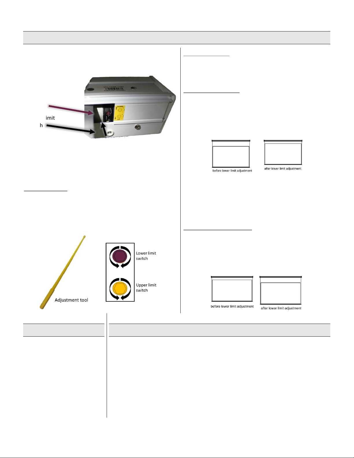
Adjusting Limit Switches
Limit switches are located on the left side of the screen and
inside the housing. The limit switches should only be adjusted
with the provided adjustment tool.
The limits that are set determine the point where the screen will
stop lowering or retracting. By initially adjusting the lower limit,
the screen will stop at the perfect location automatically for
maximum convenience.
UPPER LIMIT
The upper limit switch is yellow and does not need to be
adjusted as it is pre-set from the factory. If absolutely necessary,
turning the grey upper limit switch counter-clockwise will cause
the upper limit to be closer to the housing and clockwise will
make the upper limit further away from the housing.
LOWER LIMIT
The lower limit switch is purple and can be adjusted for
increasing or decreasing the amount of upper black drop on
your screen.
REDUCING BLACK DROP
To decrease the amount of black drop, first lower the screen
and turn the purple lower limit switch clockwise twice.
Retract the screen then lower the screen again and where it
stops is the new lower limit. Repeat until the desired height is
reached.
The first time the lower limit is being adjusted, it may take a
few cycles for the screen to move up. This is normal and be
patient as to not damage the screen. If the screen pauses
during adjustment, wait 5 minutes for the motor to cool and
continue adjusting.
INCREASING BLACK DROP
To increase black drop, lower the screen so it is fully
extended. Using the adjustment tool, turn the purple limit
switch counter-clockwise and the screen will drop in small
increments without needing to cycle the screen. Continue
rotating until the screen is in the desired position.
Overheat Protection
The motor used in this screen has
an overheat protection feature.
When the motor runs for an
extended period, the motor will
stop working to prevent
overheating which would cause
damage to the motor. If this
happens, wait 15-20 minutes for
the motor to cool off and
continue use.
Fuse Replacement
There is a fuse located on the screen’s circuit board to prevent additional electrical damage
to the unit in an electrically unstable environment. If the screen appears to have no power
while the outlet provides power, the fuse may be blown. It is the user’s responsibility provide
an electrically stable environment for the unit, and to replace the fuse if required.
Remove the screws on the side of the housing with the power cable and take off the side
covering. Carefully pull out the circuit board while ensuring no wires are damaged. Take off
the black plastic cover labelled “FUSE” and see if the fuse is blown. If this is the case, remove
the fuse from the plastic casing using tweezers or a lever to remove. Replace the fuse with
the same model as the one removed. The model will be labelled on the fuse. Replace the fuse
cover, put the circuit board back in its original location and replace the side cover.
Lower Limit
Switch
Upper Limit
Switch
Up Down
Up Down
Other manuals for Luna
1
Other EluneVision Accessories manuals


