ElyQ Vision 50 User manual

USER MANUAL
MANUALE D’USO
BENUTZER HANDBUCH
MANUEL D'UTILISATION
ElyQ

EN DE FRIT
Introduction
Congratulation for your choice! Our Vision 50 is
designed for modelers who love building and flying an
highest quality model helicopter. The Vision 50 requires
a short time for assembly and easy maintenance using
standard hobby tools. This model, thanks to high
performance and top flight features, is ideal for both
beginner and expert pilots.
Warning
The Vision 50 is a precision machine requiring proper
assembly and setup in order to avoid serious body
injury. The manufacturer and distributors assume no
liability for damages that could occur from the
assembly or misuse of this product. It is under owner
responsibility to operate the helicopter in a safe mode,
so we recommend seeking help and guidance from
other accomplished model helicopter pilots to ensure
quick and successful learning.
Read carefully this manual first
Keep the model KIT parts away from children.
Once finished assembling, the model is ready for
testing; it is highly recommended that beginners seek
the help of experienced RC helicopters pilots, or
contact a Flying Club in order to get the necessary
knowledge on how to use the model.
If you are in doubt of your ability or on the current safety
rules, we strongly recommend you to ask for
assistance from experienced radio controlled
helicopter modelers or join your local model flying club
to gain the required knowledge and skill.
ElyQ does not assume the liability for the use and / or
misuse of the model.
This model is not a toy.
ElyQ reserves the right to make any changes
considered necessary without prior notice and shall not
be liable for technical or editorial errors or omissions
contained herein. For updates or further info, please
visit our site www.elyq.com
Introduzione
Congratulazioni per aver scelto il nostro modello Vision
50, un elicottero studiato con l’obbiettivo di rendere
estremamente semplice il montaggio e soprattutto la
manutenzione. Questa meccanica, grazie alle elevate
prestazioni e caratteristiche di volo che la distinguono,
è ideale sia per i principianti che per i più esperti.
Avvertenze
L’elicottero Vision 50 è un apparecchio di precisione
che richiede un corretto assemblaggio e settaggio per
evitare incidenti o conseguenze che potrebbero
risultare dannose. E’ responsabilità del possessore
utilizzare in maniera corretta e sicura il modello, per
evitare danni a cose o persone, a causa di mancanza di
sicurezza o di uso scorretto.
Leggere prima questo manuale di montaggio.
Non lasciate che i bambini utilizzino il materiale incluso
nel KIT senza la supervisione di un adulto.
Una volta completato il montaggio ed installato con
cura i componenti necessari, il vostro modello è pronto
per il collaudo. Se non avete ancora un sufficiente
controllo nel volo, raccomandiamo caldamente
l’assistenza di personale dotato di esperienza nel
telecomandare gli elicotteri o di rivolgersi al Vs. “Flying
Club” per acquisire la necessaria conoscenza e utilizzo
del prodotto.
Chiedete informazioni, tramite personale dotato di
esperienza, in riferimento alle norme di sicurezza
durante le prove e i voli. Anche in questo caso
suggeriamo di rivolgersi al Vs. più vicino “Flying Club”
per acquisire le norme sulla sicurezza relative agli
elicotteri R/C.
Se è il Vision 50 è il vostro primo elicottero R/C che
assemblate raccomandiamo caldamente di farvi
assistere da un pilota esperto per la messa a punto e
per le prime istruzioni di volo.
ElyQ non si assume nessuna responsabilità relativa
all’uso del prodotto.
Questo modello non è un giocattolo.
ElyQ declina ogni responsabilità per eventuali errori
e/o imprecisioni nelle informazioni riportate e si
riserva il diritto di apportare ogni modifica ritenuta
necessaria, senza alcun preavviso.
Visitate il nostro sito per eventuali aggiornamenti e/o
ulteriori informazioni: www.elyq.com
Einleitung
Wir gratulier en Ihnen zu der Wahl unseres
Hubschraubers Vision 50. Dieser Hubschrauber wurde
mit dem Ziel entworfen, die Montage und vor allem die
Wartung extrem leicht zu gestalten. Dieses Modell eignet
sich d ank seine r Leis tu ngen und o pt imalen
Flugeigenschaften ideal für Anfänger und für Experten.
Hinweise
Der Hubschrauber Vision 50 ist ein Präzisionsgerät, das
eine korrekte Montage und Einstellung verlangt, um
Unfälle oder Schaden bringende Folgen zu vermeiden. Es
liegt in der Verantwortung des Benutzers, das Modell
korrekt und sicher zu benutzen, um Schäden an
Gegenständen und Personen zu vermeiden, die auf Grund
von fehlender Sicherheit und nicht korrektem Gebrauch
entstehen können.
Lesen Sie zuerst dieses Montagehandbuch.
Lassen Sie Kinder nicht das Material, das in dem Bausatz
enthalten ist, benutzen.
Wenn die Montage abgeschlossen ist und die notwendigen
Komponenten installiert sind, ist Ihr Modell bereit für die
Endkontrolle; wenn Sie noch keine ausreichenden
Erfahrungen mit dem Umgang eines Modellhubschrau
bers haben, empfehlen wir Ihnen die Unterstützung durch
erfahrene Piloten. Wenden Sie sich an Ihren nächstgele
genen Modellflugverein, um die notwendigen Kenntnisse zu
erwerben und das Fliegen zu lernen.
Informieren Sie sich auch über die Sicherheitsvorschriften
während der Tests und des Flugs. Auch in diesem Fall
empfehlen wir Ihnen, sich an den nächsten Modellflugve
rein zu wenden, um die Sicherheitsnormen für die Hub
schrauber R/C zu bekommen.
Für ferngesteuerte Flug modelle besteht die generelle
Pflicht einer Modellflug-Haftpflichtversicherung. Eine
private Haftpflichtversiche rung ist nicht ausreichend.
ElyQ übernimmt keinerlei Verantwortung bezüglich des
Gebrauch des Produkts.
Dieses Modell ist kein Spielzeug.
ElyQ entzieht sich jeglicher Verantwortung für eventuelle
Fehler und/oder Abweichungen bei den angegebenen
Informationen und behält sich außerdem das Recht vor,
jede für notwendig gehaltene Veränderung ohne
Vorankündigung vorzunehmen.
Besuchen Sie unsere Webseite für eventuelle
Aktualisi erungen und weit er e Informati one n:
www.elyq.com
Introduction
Nous tenons à vous féliciter d'avoir choisi notre
hélicoptère Vision 50, un hélicoptère étudié dans
l'objectif de rendre extrêmement simple le montage et
surtout l'entretien. Ce modèle, grâce aux prestations et
aux caractéristiques élevées de vol, est idéal pour les
débutants et pour les personnes les plus expérimentées.
Avertissements
L'hélicoptère Vision 50 est un appareil de précision qui
demande un assemblage et un réglage correct pour
éviter tout accident ou des conséquences qui pourraient
s'avérer nuisibles. Le propriétaire de l'hélicoptère est
responsable de son utilisation correcte et sûre, pour
éviter des dommages aux choses ou aux personnes, à
cause de manque de sécurité ou d'usage incorrect.
Lire auparavant ce manuel de montage.
Ne pas laisser le matériel inclus dans le KIT à la portée
des enfants.
Une fois le montage terminé et les composants
nécessaires installés, votre modèle est prêt pour l'essai;
mais vous n'avez pas encore un contrôle suffisant du vol,
par conséquent nous vous conseillons vivement de
recourir à l'assistance de personnel expérimenté dans la
télécommande des hélicoptères ou de vous adresser à
votre “Flying Club” pour acquérir les connaissances
nécessaires pour utiliser ce produit.
Demandez des informations, par l'intermédiaire du
personnel expérimenté, en référence aux normes de
sécurité pendant les essais et les vols. Dans ce cas
également nous vous conseillons de vous adresser au
“Flying Club” le plus proche de votre domicile pour
prendre connaissance des normes sur la sécurité
relatives aux hélicoptères R/C.
S'il s'agit du premier hélicoptère R/C que vous réalisez.
nous vous conseillons vivement de vous faire aider par un
pilote expérimenté pour la mise au point et pour les
premières instructions de vol.
ElyQ ne se peut être tenue responsable quant à
l'utilisation du produit.
Ce modèle n'est pas un jouet.
ElyQ décline toute responsabilité en cas d'éventuelles
erreurs et/ou imprécisions dans les informations
reportées et se réserve le droit d'apporter toute
modification jugée nécessaire, sans aucun préavis.
Visitez notre site pour des mises à jour éventuelles
et/ou ultérieures informations: www.elyq.com
ElyQIntroduction / Introduzione / Einführung / Introduction
Vision 50 - Ultimate / Italy 01-06-2008
ElyQ
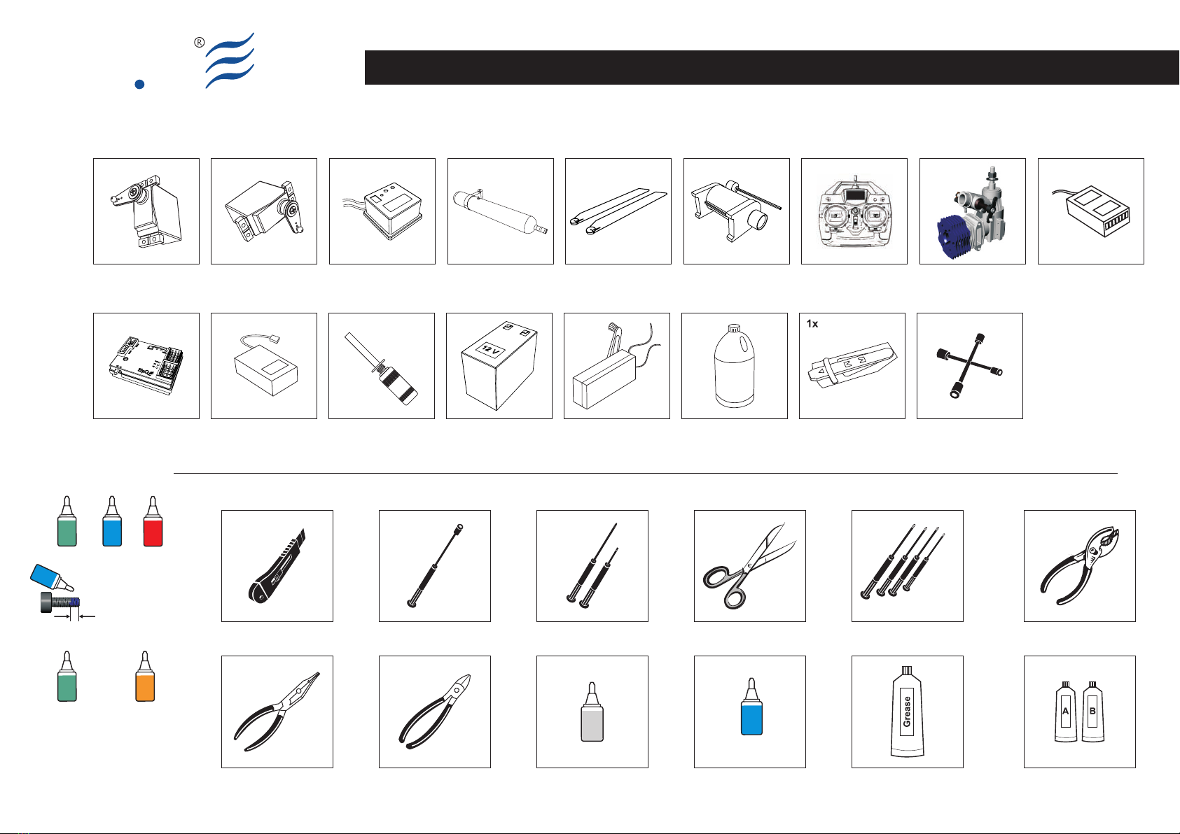
Equipment required for Assembly
ScissorsScrew DriversHobby cutter knife Socket Drivers
5.5
7
8
10
Cutting Pliers Epoxy
Grease
Ball Link Pliers
PliersHex Wrench
1.5
2
2.5
3
Cyano Acrylate
Cyano
acrylate
Blue Lockite
Blue
Locktite
243
Standard Servo
4x
600/620 Blades
1x set
ElyQ - Voltage Regulator
1x
Recommended
Tools required for assembly - Attrezzi richiesti per l’assemblaggio - Benötigte Werkzeuge für die Montage - Outils nécessaires pour l'assemblage
Heli Engine (.50)
1x
Specific Tail Servo
1x
Muffler (.50)
1x
Engine Starter
1x
Receiver (6ch or more)
1x
Transmitter 6ch or more
1x
Helicopter System
Head Lock Gyro
1x
7.4V-1.5A/2A Lipo Battery
1x
12V Battery
1x
Glow Starter
1x
Fuel Pump
1x
Fuel Glow Plug Wrench
1x
Pitch Gauge
Vision 50 - Ultimate / Italy 01-06-2008
Blue
Locktite
243
Red
Locktite
222
Green
Locktite
680
Green
Locktite
638 641
Yellow
Locktite
Glue width: approx. 1mm
Locktite
Retention of bearings onto
shafts and into housings

ElyQ
S001-1
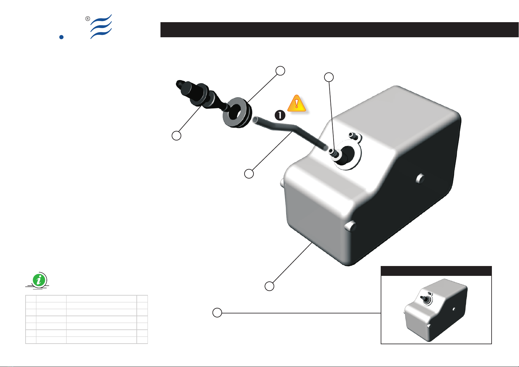
Fuel Tank Assy
BAG EQ5000
EN DE FRIT
(Bag EQ5000)
Fuel Tank Assembly
The fuel tank comes assembled from the
factory.
The Silicon fuel clunk tube (4), plugged
into the Fuel Tank (3), has a top
quality feature and it is designed in order
to work with very high nitromethane
percentage. In spite of this
characteristic, we recommend to make
periodic controls to avoid possible
anomalies. If the control should highlight
deterioration, we suggest a replacement,
otherwise it can break off.
(Bag EQ5000)
Fuel Tank Assembly
Questa parte viene fornita già
assemblata.
Il Silicone fuel clunk tubing (4) inserito
nel Fuel Tank (3) è di ottima qualità ed
il materiale è stato selezionato per
operare con percentuali di nitrometano
molto alte. Ciò nonostante è consigliabile,
al fine di evitare possibili anomalie, di
effettuare controlli periodici. Qualora si
dovesse evidenziare un deterioramento
se ne suggerisce la sostituzione.
(Bag EQ5000)
Fuel Tank Assembly
Dieses Teil wird bereits montiert
geliefert.
Der Silikonschlauch (4), der in den
Kraftstofftank (3) eingesetzt wird, hat
eine optimale Qualität, damit auch sehr
hoch nitromethanhaltiger Sprit benutzt
werden kann. Dennoch ist es ratsam,
eine regelmäßige Kontrolle durchzufüh
ren, um mögliche Schäden am Schlauch
und am Tank zu vermeiden. Falls die Kon
trolle eine Verschlechterung aufweisen
sollte, ist eine sofortige Erneuerung not
wendig.
(Bag EQ5000)
Fuel Tank Assembly
Cet ensemble est fourni déjà assemblé.
Le Silicone fuel clunk tubesng (4)
inséré dans le Fuel Tank (3) est
d'excellente qualité et le matériel a été
sélectionné pour opérer avec des
pourcentages de nitrométhane très
élevés. Cependant il est conseillé, afin
d'éviter de possibles anomalies,
d'effectuer un contrôle périodique. Au
cas où le contrôle devait révéler une
détérioration, il est conseillé de procéder
au remplacement.
Vision 50 - Ultimate / Italy 01-06-2008
Preview
ElyQFuel Tank Assy
BAG EQ5000
5
4
3
2
1
6
S001-2
1 8003100A Fuel tank stopper 1
2 8003200A Fuel tank nipple 1
3 8003300A Fuel tank 1
4 8003400A Silicone fuel clunk tubing 1
5 8103600A Fuel Clunk 1
6 8400500A Fuel Tank Assy
Vision 50 - Ultimate / Italy 01-06-2008

ElyQ
S002-1
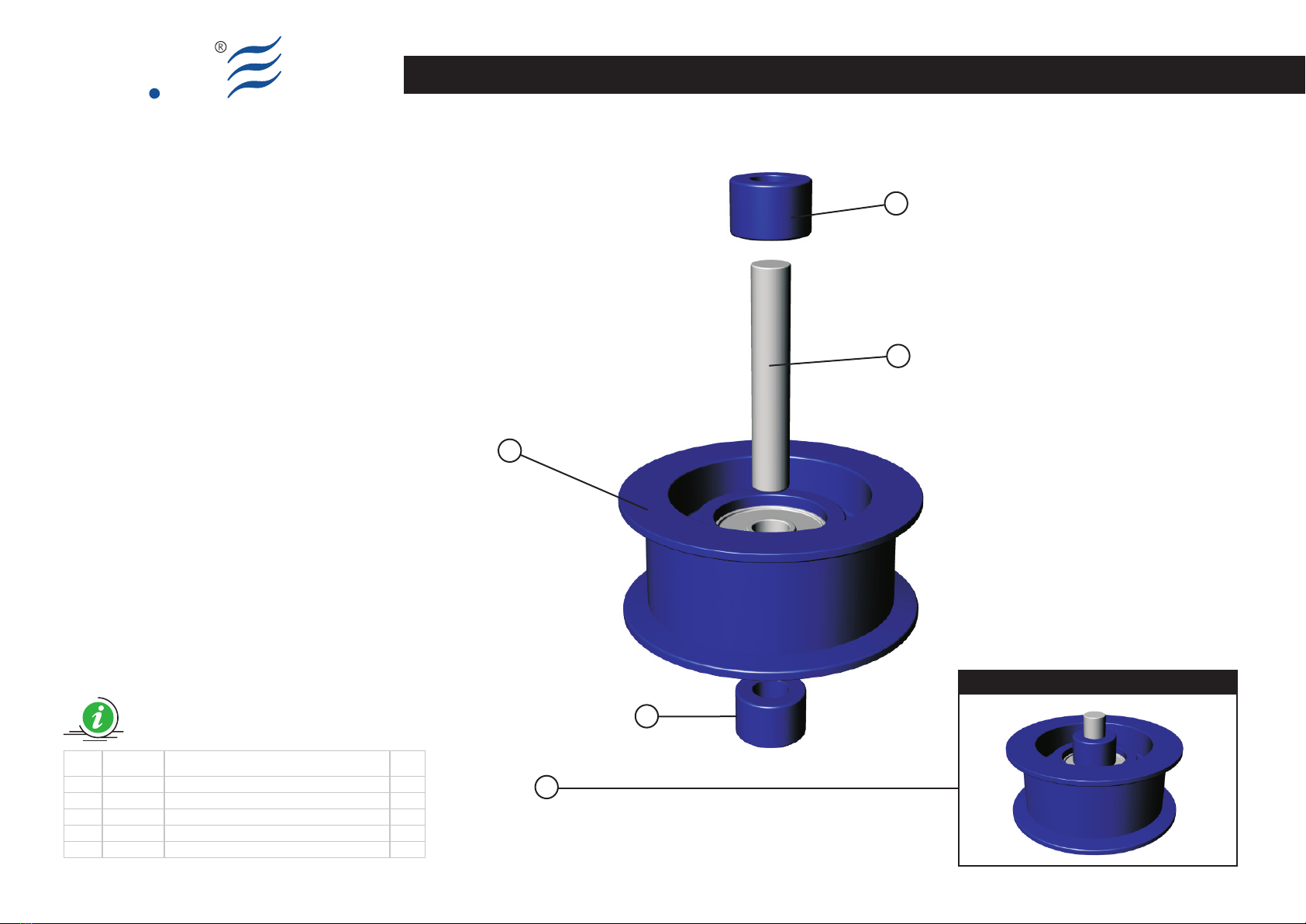
Guide Pulley Assy
BAG EQ5001
EN DE FRIT
(Bag EQ5001)
Guide Pulley Assy
Insert the PIN (3) in the Guide Pulley (2)
bearing and locking them symmetrically
using the Pulley collar (1).
(Bag EQ5001)
Guide Pulley Assy
Inserire il PIN (3) nel relativo cuscinetto
situato nella Guide Pulley (2) e fermarlo,
simmetricamente, con i Pulley collar (1).
(Bag EQ5001)
Guide Pulley Assy
Setzen Sie den PIN (3) in das Lager des
Rads Guide Pulley (2) ein und befestigen
Sie es symmetrisch mit den Pulley Collar
(1).
(Bag EQ5001)
Guide Pulley Assy
Introduire le PIN (3) dans le coussinet
relatif à la roue Guide Pulley (2) et
l'arrêter, symétriquement, avec les Pulley
collar (1).
Vision 50 - Ultimate / Italy 01-06-2008
Preview
4
3
2
1
1
Guide Pulley Assy
ElyQ
Item Code Description Q.ty
1 8004000A Pulley collar 2
2 8004100A Guide pulley with bearing d3, D10, W4 1
3 8103800A Pin Ø 3x17.75 1
4 8400800A Guide pulley assy
S002-2
BAG EQ5001
Vision 50 - Ultimate / Italy 01-06-2008

ElyQ
S003-1
Landing Skid Assy
BAG EQ5002
EN DE FRIT
(Bag EQ5002)
Landing Skid Assy
Insert the skid pipe (3) in the
corresponding holes of the Landing gear
strut (2).
Install the screws (4), according to the
drawing, but don't over tight them.
Please keep the screws
perpendicular to the housing, and
make the first turns with caution, in
order to avoid breaking to the
corresponding housing.
Before installing the plastic End Caps
(1), please add a drop of thick CA glue
on the rim of the End Caps (1) and on the
inside edge of the Landing Pipes (2). Now
it is possible to fasten deeply the caps.
(Bag EQ5002)
Landing Skid Assy
Inserire i tubi (3) nei fori relativi dei
Landing gear strut (2).
Inserire e avvitare, senza fissare fino in
fondo, le viti (4) seguendo lo schema di
montaggio.
Attenzione l’inserzione deve avvenire
cercando di mantenere la massima
perpendicolarità ed eseguendo i primi giri
con cautela al fine di evitare rotture alla
relativa sede.
Inserire per circa 1mm le coperture
in plastica (1) nei tubi (3) seguendo lo
schema di montaggio e assicurarsi che
rimanga sufficiente area prima della
battuta finale.
Versare una goccia di CA per parte
sull’area ancora scoperta della
copertura in plastica (1) e quindi inserire
fino in fondo nei rispettivi tubi (3).
(Bag EQ5002)
Landing Skid Assy
Setzen Sie die Rohre (3) in den
entsprechenden Löchern der Landing
Gear Strut (2) ein.
Setzen Sie die Schrauben (4)ein und
schrauben Sie diese fest, ohne zu fest an
zuziehen. Folgen Sie dem Montagesche
ma.
Achten Sie darauf, dass die
Schrauben (4) senkrecht eingesetzt
werden und dass die ersten Drehungen
vorsichtig ausgeführt werden, da ein
Überdrehen das Gewinde beschädigen
würde.
Setzen Sie die Kunststoffabdeckun
gen (1) ca. 1mm weit in die Rohre (3)
ein, indem Sie dem Montageschema
folgen und vergewissern Sie sich, dass
genug Platz vor dem Endanschlag bleibt.
Geben Sie nun einen Tropfen CA-
Schnellkleber auf den Bereich, der noch
nicht mit der Kunststoffabdeckung
bedeckt ist (1) und drücken Sie diese
komplett in die Rohre (3) rein.
(Bag EQ5002)
Landing Skid Assy
Introduire les tubes (3) dans les trous
relatifs des Landing gear strut (2).
Introduire et visser, sans fixer à fond, les
vis (4) en suivant le schéma de montage.
Attention l'insertion doit être
effectuée en cherchant à maintenir la
perpendicularité maximum et en
exécutant les premiers tours avec
précaution afin d'éviter des ruptures au
logement relatif.
Introduire environ 1mm des
couvertures en plastique (1) dans les
tubes (3) en suivant le schéma de
montage et vérifier qu'il reste un espace
suffisante avant la butée finale.
Verser une goutte de CA en partie sur la
zone encore découverte de la couverture
en plastique (1) et ensuite l'introduire
dans les tubes (3).
Vision 50 - Ultimate / Italy 01-06-2008

Preview
ElyQLanding Skid Assy
4
3
2
1
S003-2
Cyano
acrylate
Item Code Description Q.ty
1 8003500A Skid pipe end cap 4
2 8007800A Skid Brace 3D - V50 2
3 8103700A Landing gear skid pipe 2
4 8204600A Set screw M4x4 4
BAG EQ5002
Vision 50 - Ultimate / Italy 01-06-2008

ElyQ
EN DE FRIT
(Bag EQ5003)
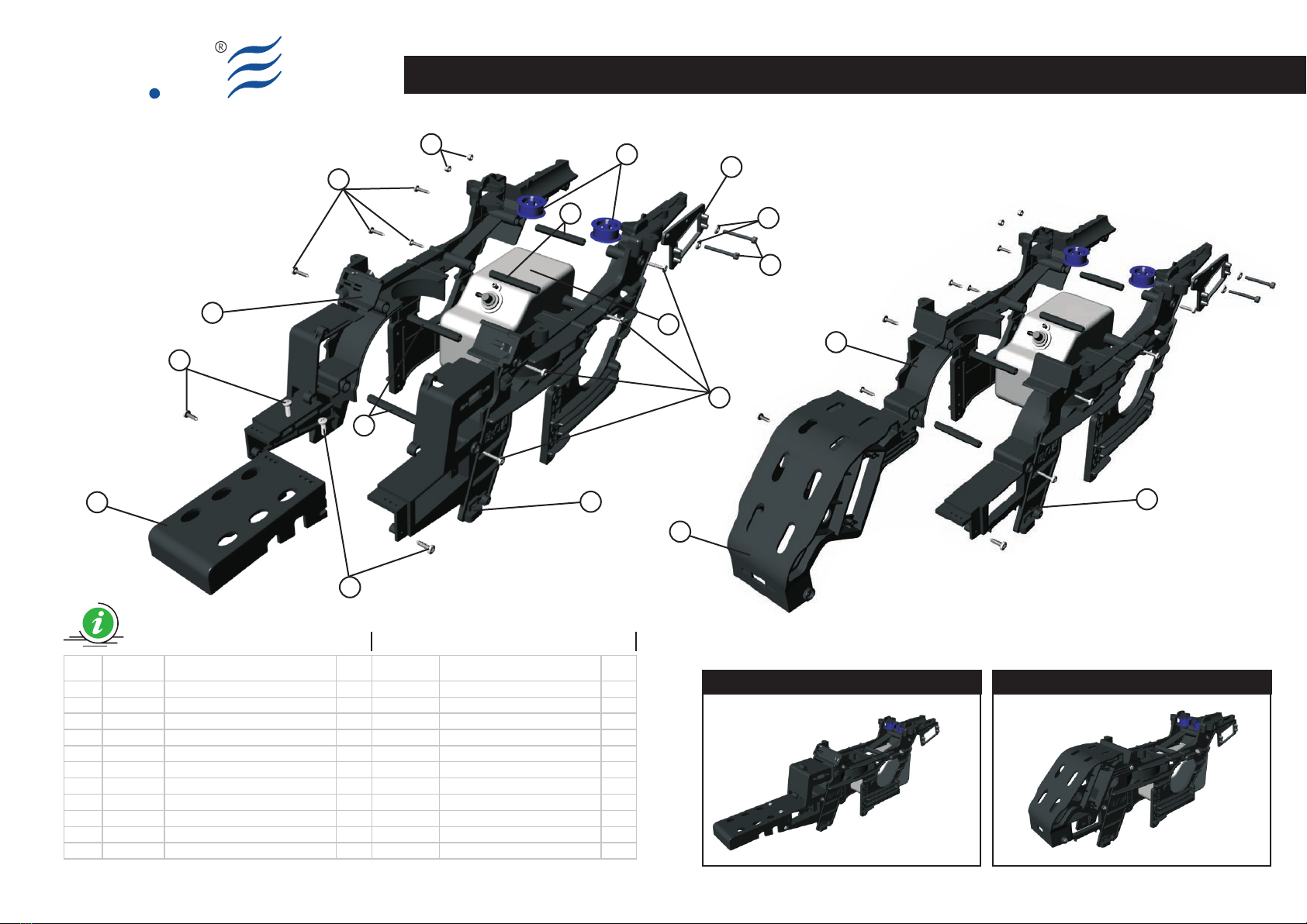
Main Frame Assembly (Part 01)
Make up the assy according to the
drawing.
The fuel tank (6) and the Guide pulley (1)
have already been assembled.
The self trapping screws (9) must not be
over tighten, because they must ensure a
good seal without over fastening.
(Bag EQ5003)
Main Frame Assembly (Part 01)
Eseguire il montaggio secondo lo
schema.
Il serbatoio (6) e le ruote guida cinghia
(1) sono state già assemblate
precedentemente.
Le viti autofilettanti (9) non devono
essere serrate in maniera eccessiva.
Le stesse devono assicurare una buona
tenuta ma senza eccedere nel serraggio.
(Bag EQ5003)
Main Frame Assembly (Part 01)
Führen Sie die Montage nach dem
Schema aus.
Der Tank (6) und die
Riemenführungsräder (1) wurden schon
vorher montiert.
Die selbstschneidenden Schrauben (9)
müssen einen guten Halt garantieren,
ohne diese zu überdrehen.
(Bag EQ5003)
Main Frame Assembly (Part 01)
Exécuter le montage selon le schéma.
Le réservoir (6) et les roues de guidage
courroie (1) ont été déjà assemblés au
préalable .
Les vis auto-taraudeuses (9) ne doivent
pas être excessivement serrées.
Celles-ci doivent assurer une bonne tenue
mais sans excéder dans le serrage.
Main Frame Assembly (Part 01)
BAG EQ5003
S004-1 Vision 50 - Ultimate / Italy 01-06-2008
Main Frame Assembly (Part 01)
ElyQ
S004-2
4
9
9
9
9
8
11
3
10
2
7
7
5
6
1
Preview
BAG EQ5003
Preview (V50 Ultimate)
Item Code Description Q.ty Code Description Q.ty
1 8400800A Guide pulley assy 2
2 8000200A Lower Main Frame (Right) 1 8000200B Lower Main Frame (Right) 1
3 8000100A Lower Main Frame (Left) 1 8000100B Lower Main Frame (Left) 1
4 8000500A Radio tray 1 8007300B Radio tray 1
5 8006100A Rudder Servo Tray CF 1
6 8400500A Fuel Tank Assy 1
7 8002100A Frame Spacer (L) 4
8 8202800A Socket Screw M3x25 2
9 8200000A Self Tapping Screw 3x12 12 8200000A Self Tapping Screw 3x12 10
10 8200400A Lock Nut M3 2
11 8201200A Flat Washer d3, D8, W1.5 2
4
2
Vision 50 Ultimate
3
Vision 50 Ultimate
Vision 50 - Ultimate / Italy 01-06-2008

ElyQ
S005-1
EN DE FRIT
(Bag EQ5004)
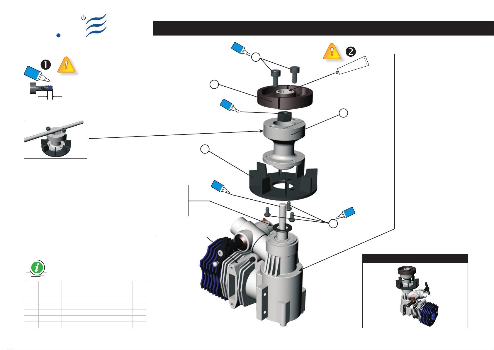
Cooling Fan Assy
Make up the assy according to the
drawing.
First of all, secure the Fan (1) to the Hub
(3) using the Socket button head screws
(5). If the helicopter will be provided with
a “Governor” device, the Fan (1) is
already equipped with the corresponding
sensor housings (please see “Governor”
add-on – not included).
Un-mount the cover plate of the engine
crankcase and insert the corresponding
Crankshaft locking tool in order to fasten
the shaft (please see engine notes – not
included).
Add the sub-assembly to the engine
crankshaft. Then use the screws (4),
temporarily screw in the Hub (3), and
tighten the hub with an appropriate tool.
Remove the screws (4), fasten the prop
nut of the engine Crankshaft and mount
the Clutch (2) using the screws (4).
Remove the Crankshaft Clamp from the
engine, and then close the carter.
Each screw identified by the “Locktite”
symbol, must be impregnated with a
small drop of medium seal Locktite (blue)
along the entire length.
Add one-way bearing grease to the
corresponding Clutch (2). Repeat this
operation during the ordinary
maintenance of the helicopter.
(Bag EQ5004)
Cooling Fan Assy
Eseguire il montaggio seguendo lo schema.
Come prima operazione fissare la ventola
(1) all’HUB (3) utilizzando le viti (5). Qualora
si decidesse di utilizzare un dispositivo
”Governor” (regolatore di giri) la Ventola
(1) è già dotata delle opportune sedi per
l’accoglienza dei magneti (vedi istruzioni
allegate al “Governor” - non incluso).
Rimuovere il carter motore e inserire
l’apposito fermo (Crankshaft Clamp)
affinché l’albero motore non sia più libero
di ruotare (vedi istruzioni relative al motore
- non incluso).
Avvitare il gruppo all’albero motore
utilizzando le Viti (4) superiori,
provvisoriamente avvitate direttamente
sull’HUB (3) e fare leva, con un giravite
appositamente inserito (vedi fig.1),
assicurandone il giusto serraggio.
Rimuovere le viti (4), serrare
opportunamente il dado dell’albero
motore e montare il Clutch (2) fissandolo
con le viti (4). Rimuovere il fermo
(Crankshaft Clamp) di bloccaggio
dell’albero motore e richiudere il carter.
Ogni vite, identificata con il simbolo
“Locktite”, deve essere
preventivamente impregnata di Locktite a
tenuta media (blu).
Versare del grasso per cuscinetti
unidirezionali nel relativo Clutch (2).
Ripetere questa operazione durante la
periodica manutenzione dell’elicottero.
(Bag EQ5004)
Cooling Fan Assy
Führen Sie die Montage nach dem Schema aus.
Zuerst muss das Lüftungsrad (1) am HUB (3)
mit den Schrauben (5) fixiert werden. Für den
Fall, dasss Sie den Hubschrauber mit einem
Drehzahlregler (Governor) auszustatten
möchten, ist das Gebläse (1) bereits mit den
geeigneten Vertiefungen für die Sensoren (nicht
im Lieferumfang enthalten - beachten Sie ihre
beiliegende Anleitung des Drehzahlreglers)
ausgestattet.
Demontieren Sie den Boden des Motorgehäu
ses und setzen Sie die entsprechende Stift
schraube ein (Crankshaft Clamp), damit die
Welle blockiert wird (beachten Sie die Anleitung
des Motors – nicht im Lieferumfang).
Schrauben Sie die Gruppe an die Motorwelle an
und drehen Sie mit Hilfe der oberen Schrauben
(4), die provisorisch direkt auf dem HUB (3)
angeschraubt sind, mit einem Schraubendreher
(siehe Abb.1) die Baugruppe fest an. Entfernen
Sie die Schrauben (4), befestigen Sie die Schrau
benmutter (im Lieferumfang des Motor enthal
ten) auf die Motorwelle und montieren Sie die
Fliehkraft-Kupplung (Clutch (2)) mit den Schrau
ben (4). Entfernen Sie den Sicherungsstift (Cra
nkshaft Clamp) der Motorwelle und schließen
Sie das Gehäuse wieder.
Wo das Symbol “Locktite” angebracht ist,
muss jede Komponente mit Locktite mittel
fest (blau) gesichert werden.
Geben Sie Schmiermittel in den Freilauf der
Kupplung (Clutch (2)). Wiederholen Sie
diesen Vorgang während der regelmäßigen
Wartung des Hubschraubers.
(Bag EQ5004)
Cooling Fan Assy
Exécuter le montage en suivant le schéma.
Comme première opération fixer le
ventilateur (1) à l'HUB (3) au moyen des vis
(5). Au cas où l'on décide de doter
l'hélicoptère d'un dispositif ”Governor” le
ventilateur (1) est déjà doté des logements
opportuns pour accueillir des capteurs
(voir instructions aux gate au “Governor” -
non inclus).
Démonter le fond du carter moteur et
introduire le pivot spécialement prévu
(Crankshaft Clamp) afin que l'arbre se
bloque (voir instructions relatives au
moteur - non inclus).
Visser le groupe à l'arbre moteur et au
moyen des vis (4) supérieures,
provisoirement vissées directement sur
l'HUB (3), et un tournevis servant de levier,
en l'insérant entre celles-ci (voir fig.1),
jusqu'au serrage. Enlever les vis (4), fixer
solidement l'écrou de l'arbre moteur et
monter le Clutch (2) en le fixant avec les vis
(4). Enlever le pivot (Crankshaft Clamp) de
blocage de l'arbre moteur et refermer le
carter.
Chaque vis, où est reporté le symbole
“Locktite”, doit être au préalable
imprégnée de Locktite à tenue moyenne
(bleue).
Verser de la graisse pour roulements
unidirectionnels dans le Clutch (2)
relatif. Répéter cette opération pendant
l'entretien périodique de l'hélicoptère.
Cooling Fan Assy
BAG EQ5004
Vision 50 - Ultimate / Italy 01-06-2008
Preview
ElyQCooling Fan Assy
Item Code Description Q.ty
1 8000600A Fan 1
2 8401000A Clutch assy 1
3 8100400B Fan HUB 1
4 8202300A Socket screw M4x8 2
5 8202400A Socket button head screw M3x6 3
4
Blue
Locktite
3
2
1
5
Blue
Locktite
Blue
Locktite
Blue
Locktite
Grease
for one way bearing
Glue width: approx. 1mm
Blue
Locktite
S005-2
Engine not included
EN
IT
DE
FR
BAG EQ5004
Fig. 1
ElyQ ha realizzato, specificatamente per
questa classe di elicottero, un nuovo
motore (.57cc) particolarmente
potente e stabile.
I test si stanno completando durante la
stesura di questo manuale: verificate sul
sito www.elyq.com lo stato del progetto e
le date di disponibilità dello stesso.
ElyQ entwickelt einen Motor (.57cc), der
besondere Laufeigenschaf ten und
Leistung bietet. Die Tests des Motors
laufen zurzeit. Bitte besuchen Sie unsere
Website www.elyq.com für mehr Infor
mationen und den Erscheinungstermin
ElyQ a été créé spécifiquement pour
cette classe d'hélicoptère, un nouveau
moteur (.57 cc) particulièrement
puissant et stable.
Les essais sont en train de terminer au
cours de la rédaction de ce manuel,
consultez le site www.elyq.com l'état
d'avancement du projet et les dates de
disponibilité de celle-ci.
ElyQ has designed, specifically for this 50
class helicopter, a new engine (.57cc)
particularly powerful, smooth and stable.
The tests are being completed during
t hes e day s . Ple ase c h ec k t h e
www.elyq.com. There you can find
project's status, dates and availability.
Vision 50 - Ultimate / Italy 17-09-2008
Non montare
Do not mount
Nicht montieren
Ne pas monter

ElyQ
S006-1
EN DE FRIT
(Bag EQ5004)
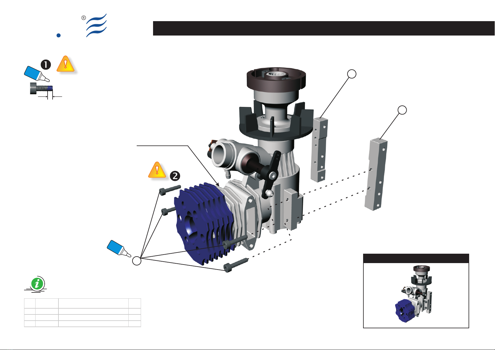
Engine Mount Assy
Make up the assy according to the
drawing.
Please be careful: don't exchange the
Engine Mount (1-2). The Mount marked
with “R” (1) must be in the Right side of
the helicopter, while the Mount marked
with “L” (2), must be in the left side.
The left / right side are identified by a
pilot sitting in the helicopter.
Each screw identified by the “Locktite”
symbol, must be impregnated with a
small drop of medium seal locktite (blue)
along the entire length.
In this stage don't fix firmly the
screws because, once assembled the
helicopter, it is necessary to rotate the
engine starter shaft (using a starter) in
order to line up the structure.
Only after this operation, it is possible to
tighten the screws (3).
(Bag EQ5004)
Engine Mount Assy
Eseguire il montaggio seguendo lo
schema.
Fare attenzione a non invertire i montanti
del motore (1-2), assicurarsi che il
montante etichettato “R” (1) sia sul
fianco destro dell’elicottero e quello
etichettato “L” (2) sia sul sinistro.
Il fianco destro e sinistro, per
convenzione, si identifica supponendo
che l’operatore sia seduto sul velivolo.
Ogni vite, identificata con il simbolo
“Locktite”, deve essere
preventivamente impregnata di Locktite
a tenuta media (blu).
In questa fase non serrare le Viti (3)
in quanto, una volta assemblato
l'elicottero, è necessario far girare a
vuoto, l'albero per l'avviamento del
motore, affinché si perfezioni
l'allineamento completo della meccanica.
Solo dopo questa operazione si potranno
serrare le Viti (3).
(Bag EQ5004)
Engine Mount Assy
Führen Sie die Montage nach dem
Schema aus.
Achten Sie auf die Beschriftungen “R” für
den rechten Motorträger (1) und “L” für
den linken Motorträger (2).
Die Ermittlung der rechten und linken
Seite beruht auf der Annahme, dass der
Betrachter von hinten auf den
Hubschrauber schaut.
Wo das Symbol “Locktite” angebracht
ist, muss jede Komponente mit
Locktite mittelfest (blau) gesichert
werden
In dieser Phase nicht die Schrauben
(3) festziehen, weil es nach der
Montage des Hubschraubers notwendig
ist, das System über den Anlasser leer
laufen zu lassen.
Dies wird solange durchgeführt, bis sich
das System an die Struktur angepasst
hat. Erst nach diesem Vorgang können
die Schrauben festgezogen werden (3).
(Bag EQ5004)
Engine Mount Assy
Exécuter le montage en suivant le
schéma.
Faire attention à ne pas inverser les
montants du Moteur (1-2), vérifier que le
montant étiqueté “R” (1) soit sur le flanc
droit de l'hélicoptère et celui étiqueté “L”
(2) soit sur le flanc gauche.
Le flanc droit et gauche, par convention,
est identifié en supposant que l'opérateur
est assis dans le véhicule.
Chaque vis, où est reporté le symbole
“Locktite”, doit être au préalable
imprégnée de Locktite à tenue moyenne
(bleue).
Dans cette phase ne pas serrer les
vis (3) car, une fois monté
l'hélicoptère, il est nécessaire de faire
tourner le système à vide, au moyen de la
visseuse.
Ceci afin que celui-ci s'aligne avec la
structure.
Seulement après cette opération les vis
(3) pourront être serrées.
BAG EQ5004 Engine Mount Assy
Vision 50 - Ultimate / Italy 01-06-2008
Preview
ElyQEngine Mount Assy
1
2
3
S006-2
Blue
Locktite
Glue width: approx. 1mm
Blue
Locktite
Engine not included
Item Code Description Q.ty
1 8101100B Engine Mount (Rigth) 1
2 8101000B Engine Mount (Left) 1
3 8200900A Socket screw M3x14 4
BAG EQ5004
Vision 50 - Ultimate / Italy 01-06-2008

ElyQ
S007-1
EN DE FRIT
(Bag EQ5004 e EQ5022)
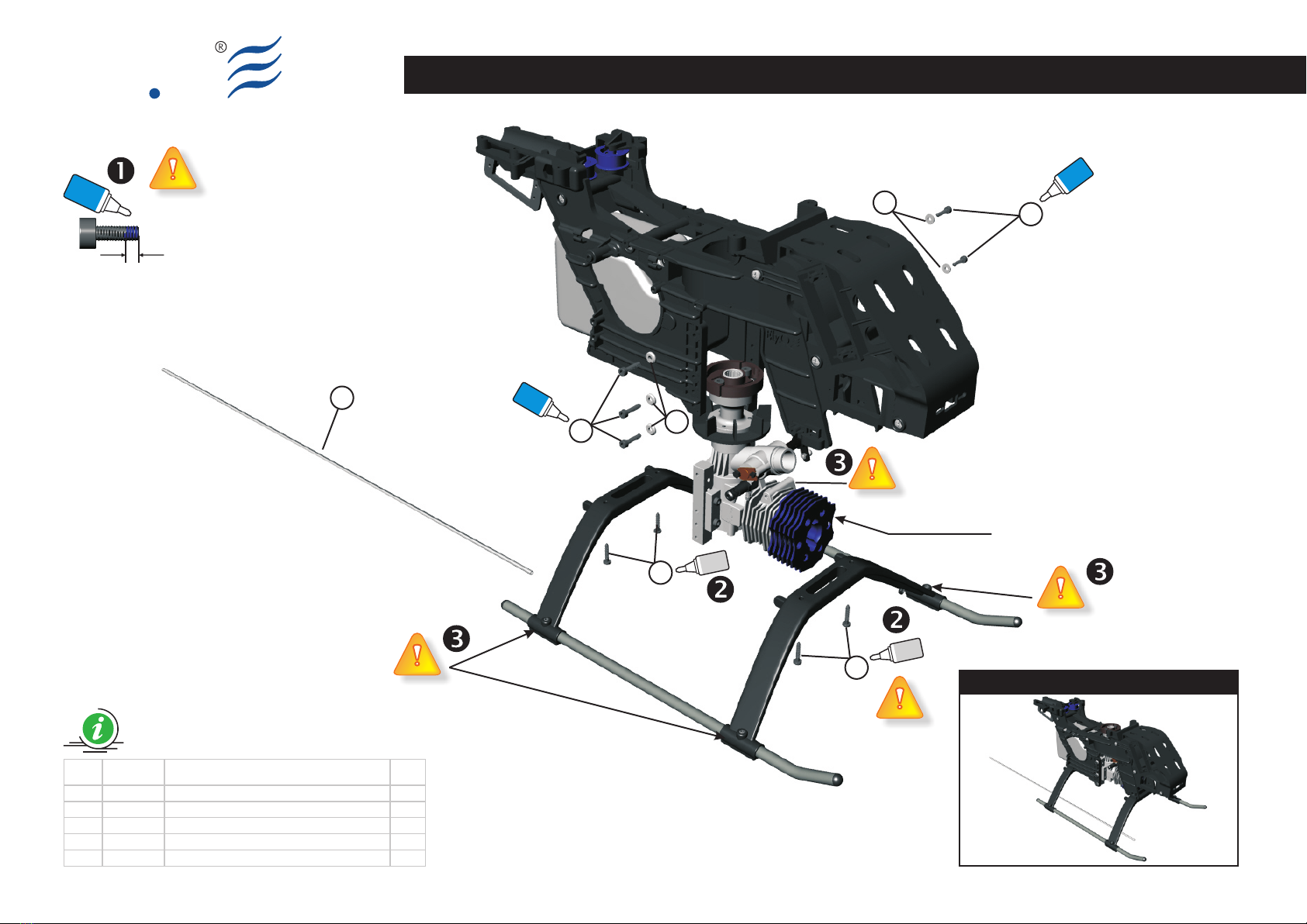
Main Frame Assembly (Part 01.1)
Make up the assy according to the
drawing.
Use the Antenna tube (4) provided with
the EQ5022 helicopter package, unless
you are using a 2.4 GHz system.
The self tapping screws (2) must not be
over tighten, because they must ensure a
good seal without over fastening.
Each screw identified by the “Locktite”
symbol, must be impregnated with a
small drop of medium seal Locktite (blue)
along the entire length.
Add a tiny drop of thick CA on the self
tapping screws (2).
Tighten the fastening screws of the
skids with the pipes already
assembled (see sheet S003).
(Bag EQ5004 e EQ5022)
Main Frame Assembly (Part 01.1)
Eseguire il montaggio seguendo lo
schema.
Il Tubo dell'antenna (4), qualora non si
utilizzasse un apparato TX-RX da 2,4Ghz,
deve essere montato secondo lo schema
e lo stesso è disponibile nella confezione
EQ5022.
Le viti autofilettanti (2) non devono
essere serrate in maniera eccessiva.
Le stesse devono assicurare una buona
tenuta ma senza eccedere nel serraggio.
Ogni vite, identificata con il simbolo
“Locktite”, deve essere
preventivamente impregnata di Locktite
a tenuta media (blu).
Versare una goccia di collante rapido
CA sulle viti autofilettanti (2).
Serrare le viti di fissaggio dei pattini
con i tubi, precedentemente
assemblati (Schema S003).
(Bag EQ5004 e EQ5022)
Main Frame Assembly (Part 01.1)
Führen Sie die Montage nach dem
Schema aus.
Das Antennenrohr (4), muss montiert
werden, wenn kein Empfangssystem mit
2,4GHz benutzt wird. Es befindet sich in
der Verpackung EQ5022.
Die selbstschneidenden Schrauben (2)
müssen einen guten Halt garantieren,
ohne diese zu überdrehen.
Wo das Symbol “Locktite” angebracht
ist, muss jede Komponente mit
Locktite mittelfest (blau) gesichert
werden.
Geben Sie einen Tropfen CA-
Schnellkleber auf die
selbstschneidenden Schrauben (2).
Fixieren Sie die Kufenrohre mit Hilfe
der Madenschrauben (siehe Schema
S003).
(Bag EQ5004 e EQ5022)
Main Frame Assembly (Part 01.1)
Exécuter le montage en suivant le
schéma.
Le tube de l'Antenne (4), au cas où l'on
utilise un sytème à 2,4G, doit être monté,
il se trouve dans l'emballage EQ5022.
Les vis auto-taraudeuses (2) ne doivent
pas être excessivement serrées.
Celles-ci doivent assurer une bonne tenue
mais sans excéder dans le serrage.
Chaque vis, où est reporté le symbole
“Locktite”, doit être au préalable
imprégnée de Locktite à tenue moyenne
(bleue).
Verser une goutte de colle rapide CA
sur les vis auto-taraudeuses (2).
Serrer les vis de fixation des patins
avec les tubes, précédemment
assemblés (Schéma S003).
Main Frame Assembly (Part 01.1)
BAG EQ5004-22
Vision 50 - Ultimate / Italy 01-06-2008
Preview
Cyano
acrylate
Cyano
acrylate
43
3
2
2
Main Frame Assembly (Part 01.1)
ElyQ
Item Code Description Q.ty
1 8200900A Socket Screw M3x14 5
2 8200100A Self Tapping Screw 3x18 4
3 8201200A Flat Washer d3, D8, W1.5 5
4 8006200A Antenna Tube 1
1
1
S007-2
Blue
Locktite
Blue
Locktite
Glue width: approx. 1mm
Blue
Locktite
Engine not included
BAG EQ5004-22
Vision 50 - Ultimate / Italy 01-06-2008

ElyQ
S008-1
EN DE FRIT
(Bag EQ5005)
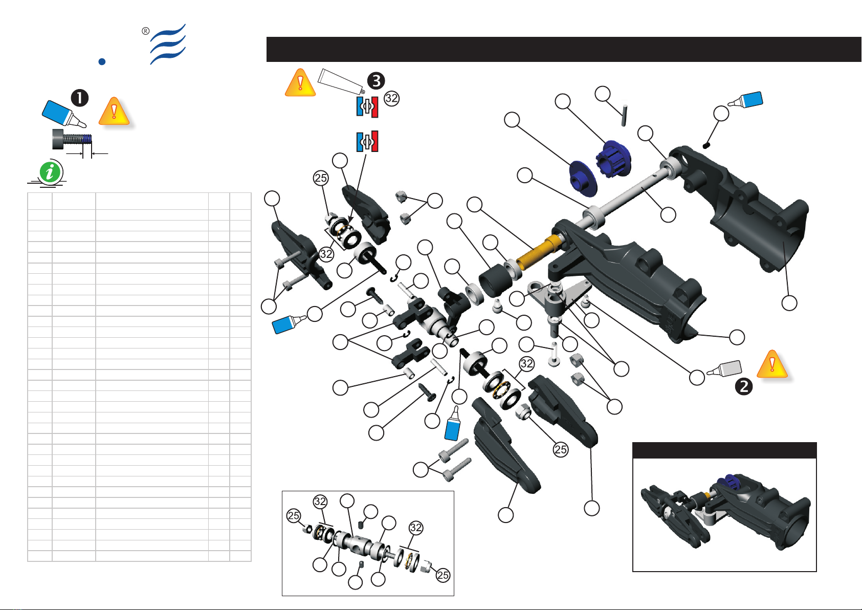
Tail Unit Assy
Make up the assy according to the
drawing.
Please take care of the PIN (13) and
screw (21) subassemblies. These
components must be tighten firmly and
the screw must be impregnated with a
small drop of medium seal locktite (blue).
The Self Tapping screws (20) and (24)
must not be over tighten, because they
must ensure a good seal without over
fastening.
Each screw identified by the “Locktite”
symbol, must be impregnated with a
small drop of medium seal Locktite (blue).
Add a tiny drop of thick CA on the Ball
Type A (14), which are to be ensured
respectively to the Tail pitch control lever
(3) and to the Tail rotor control slider ring
(10).
Insert bearing grease over the
Thrust Bearing (3). This bearing has
two external surfaces and a cage
containing little steel balls. This cage has
edges that have to be inserted towards
the surface of the bearing with the wider
diameter.
(Bag EQ5005)
Tail Unit Assy
Eseguire il montaggio seguendo lo schema.
Le parti che richiedono attenzione sono il
PIN (13) e la vite (21). Questi componenti
devono essere serrati molto bene e la vite
deve essere impregnata di Locktite media
(blu).
Le viti autofilettanti (20) e (24) non devono
essere serrate in maniera eccessiva. Le
stesse devono assicurare una buona
tenuta ma senza eccedere nel serraggio.
Ogni vite, dove è riportato il simbolo
“Locktite”, deve essere
preventivamente impregnata di Locktite a
tenuta media (blu).
Versare una goccia di collante rapido
CA sulle Ball Type A (14) da fissare
rispettivamente al Tail pitch control lever
(3) ed al Tail rotor control slider ring (10)
Lubrificate il Thrust Bearing (3) con
del grasso per cuscinetti.
Questo reggispinta si compone di tre
parti: la gabbia che ospita le sfere deve
essere compresa tra le altre due parti
aventi superficie concava. La parte della
gabbia che presenta il bordo dovrà essere
rivolta verso la superficie del cuscinetto
con il diametro interno più largo.
(Bag EQ5005)
Tail Unit Assy
Führen Sie die Montage nach dem Schema
aus.
Die Teile, die mit großer Sorgfalt montiert
werden müssen, sind PIN (13) und die
Schrauben (21).
Diese Komponenten müssen sehr gut
angezogen werden und die Schrauben
müssen mit Locktite mittelfest (blau)
gesichert werden.
Die selbstschneidenden Schrauben (20
und 24) müssen einen guten Halt
garantieren, ohne diese zu überdrehen.
Wo das Symbol “Locktite” angebracht
ist, muss jede Komponente mit Locktite
mittelfest (blau) gesichert werden.
Geben Sie einen Tropfen CA-
Schnellkleber auf die Ball Type A (14),
die an den Tail Pitch Control Lever (3) und
Tail Rotor Control Slider Ring (10) befestigt
werden.
Geben Sie Schmieröl auf die Lager für
Thrust Bearing (3).
Dieses Lager hat zwei Außenflächen
und ein Gehäuse, wo die Stahlkügelchen
eingesetzt sind. Dieses Gehäuse hat
Kanten, die in Richtung der Oberfläche des
Lagers mit dem breiteren Durchmesser
eingesetzt werden müssen.
(Bag EQ5005)
Tail Unit Assy
Exécuter le montage en suivant le
schéma.
Les parties qui requièrent plus d'attention
sont le PIN (13) et la vis (21). Ces
composants doivent être très bien serrés
et la vis doit être imprégnée de Locktite à
tenue moyenne (bleue).
Les vis auto-taraudeuses (20) et (24) ne
doivent être excessivement serrées.
Celles-ci doivent assurer une bonne tenue
mais sans excéder dans le serrage.
Chaque vis, où est reporté le symbole
“Locktite”, doit être au préalable
imprégnée de Locktite à tenue moyenne
(bleue).
Verser une goutte de colle rapide CA
sur les Ball Type à (14) qui sont
respectivement fixées au Tail pitch control
lever (3) et au Tail rotor control slider ring
(10).
Insérez de la graisse pour
roulements sur le Thrust Bearing (3).
Ce coussinet présente deux surfaces
externes et une cage où sont insérées les
billes en acier. Cette cage de tenue
présente des bords; les bords devront
être insérés vers la surface du coussinet
avec le diamètre plus large.
Tail Unit Assy
BAG EQ5005
Vision 50 - Ultimate / Italy 01-06-2008
Glue width: approx. 1mm
Blue
Locktite
31
30
30
29
29
28
28 28
28 27
27
26
26
24
24
23
23
22
22
20
21
19
18
17
16
15
15
16 14
14
13
12
11
10
9
8
7
6
5
5
4
4
3
2
1
Tail Unit Assy
ElyQ
Blue
Locktite
Blue
Locktite
Blue
Locktite
S008-2
Cyano
acrylate
Preview
Item Code Description Q.ty V2
1 8001000A Tail pulley flange 1 1
2 8001100A Tail pulley 1 1
3 8001200B Tail pitch control lever 1 1
4 8001300B Tail housing (L) 2 2
5 8001400B Tail housing (R) 2 2
6 8001600A Tail unit housing (R) 1 1
7 8001700A Tail unit housing (L) 1 1
8 8001800A Tail rotor pitch yoke 1 1
9 8001900A Tail pitch control link 2 2
10 8002000A Tail rotor control slider ring 1 1
11 8100900A Tail rotor hub SUS 1 1
12 8101300A Tail rotor shaft 1 1
13 8101500A Pin 2x12 1 1
14 8101600A Self Tapping Ball type A 2 2
15 8101700A Pin 2x10 2 2
16 8101800A Collar d2, D3, W4.3 2 2
17 8101900A Collar d3, D4, W10 1 1
18 8102000A Tail pitch slider bushing 1 1
19 8201300A Flat washer d3, D5, W0.5 1 1
20 8200100A Self tapping screw 3x18 1 1
21 8200200A Set screw M3x4 1 3
22 8600400A Bearing d5, D11, W5 2 2
23 8600500A Bearing d5, D10, W4 2 2
24 8200300A Self tapping screw 2x10 2 2
25 8200400A Lock nut M3 2 2
26 8200500A Set screw M3x18.5 2
27 8600600A Bearing d6, D10, W3 2 2
28 8200600A E-ring 4 4
29 8204700A Socket screw M2.5x8 4 4
30 8200800A Lock nut M2.5 4 4
31 8601100A Bearing d4, D7, W2.5 2 2
32 8601800A Thrust Bearing d5, D10, W4 2 2
33 8204800A Flat washer d7.5, D10, W0.5 2
BAG EQ5005
Vision 50 - Ultimate / Italy 01-12-2008
Large Internal Diameter
always go toward the
tail Rotor HUB
Small Internal Diameter
always go toward the Blade
Grease
33
23
33 23 21
21
11 V2

ElyQ
S009-1
EN DE FRIT
(Bag EQ5006)
Tail Support Rod Assy
Make up the assy according to the
drawing.
The Self Tapping screws (3) must not be
over tighten, because they must ensure a
good seal without over fastening.
Add a tiny drop of thick CA on the Self
Tapping screws (3).
(Bag EQ5006)
Tail Support Rod Assy
Eseguire il montaggio seguendo lo
schema.
Le viti autofilettanti (3) non devono
essere serrate in maniera eccessiva. Le
stesse devono assicurare una buona
tenuta ma senza eccedere nel serraggio.
Versare una goccia di collante rapido
CA sulle viti autofilettanti (3).
(Bag EQ5006)
Tail Support Rod Assy
Führen Sie die Montage nach dem
Schema aus.
Die selbstschneidenden Schrauben (3)
müssen einen guten Halt garantieren,
ohne diese zu überdrehen.
Geben Sie einen Tropfen CA-
Schnellkleber auf die
selbstschneidenden Schrauben (3).
(Bag EQ5006)
Tail Support Rod Assy
Exécuter le montage en suivant le
schéma.
Les vis auto-taraudeuses (3) ne doivent
être excessivement serrées. Celles-ci
doivent assurer une bonne tenue mais
sans excéder dans le serrage.
Verser une goutte de colle rapide CA
sur les vis auto-taraudeuses (3).
Tail Support Rod Assy
BAG EQ5006
Vision 50 - Ultimate / Italy 01-06-2008
Other manuals for Vision 50
1
Table of contents
Other ElyQ Toy manuals


Popular Toy manuals by other brands


Dream-Flight
Dream-Flight Libelle Flight and Assembly Manual

JR ProPo
JR ProPo FORZA 700 SPEED Supplemental manual

Align
Align T-REX 450X manual

American Flyer
American Flyer Defender Set owner's manual

Topmodel
Topmodel Precision Products micro Bullit manual

fischertechnik
fischertechnik ROBOTICS Mini Bots Activity booklet

GREAT PLANES
GREAT PLANES Matt Chapman Cap 580 instruction manual

FMS
FMS F-16 Fighting Falcon V2 operating manual

LEGO
LEGO Hero Eactory 44026 Assembly guide

Auhagen
Auhagen Beladegut Transformatoren quick start guide

Eduard
Eduard F-16AM S.A. quick start guide

GRAUPNER
GRAUPNER Udaloy Class Destroyer Admiral Panteleyev manual