JR ProPo FORZA 700 SPEED Owner's manual

Supplemental manual
No.88370 FORZA 700 SPEED
PLEASE READ THIS FIRST
■ All new streamlined body
■ Newly-designed landing gear to greatly reduce air resistance
■ Blended front and rear fairings for smooth airow
■ Large canopy ensures visibility at high speed
■ Super strong machined main drive gear and tail drive gear
■ All new large diameter aluminum hub supports oversize main gear for long life and ecient power transmission
Length 1,399 mm
Height 338 mm
Width 165 mm
Main rotor dia. 1,619 mm
Tail rotor dia. 262 mm
Gross weight 4,000 g ~ (not including battery)
Gear ratio 8.62:1:4.72
Main shaft dia. 12 mm
Tail output shaft dia. 6 mm
Control system 120°CCPM
Tail drive system Shaft drive
FORZA 700 SPEED Specications
The FORZA 700 has evolved into a Speed Monster.
The nely honed form minimizes air resistance, and the forward tilting
rotor head helps transform all available power into speed.
Fly beyond limits with the FORZA 700 SPEED.

P.2
SPEED MONSTER
━━━【INTRODUCTION】━━━
Thank you for purchasing this JR product.
In addition to this manual, please also refer to the FORZA 700 (standard) manual during assembly of this product.
This manual describes changes from the FORZA 700.
For each step, please read this manual rst, then refer to the FORZA 700 manual.
There are also changes to the radio setup - please refer to this manual rst.
━━━【Removed and added parts list】━━━
The table below describes part changes for each assembly step.
Removed parts from FORZA 700 Qty. Assembly procedure Added parts for FORZA 700 SPEED Qty.
Pinion gear T11 1 1-5 Pinion gear T13 1
Bevel gear B T22 1
1-6
Metal front bevel gear T22 assembly 1
Tail pinion shaft 1 Poly slider 6 x 9.5 x 0.13 1
Bevel gear pin Φ2.3 1
Setscrew M3 x 6 1
Body catch L21 2 2-3 Body catch L23 2
Body catch L21 2
2-4
Carbon tray S 1
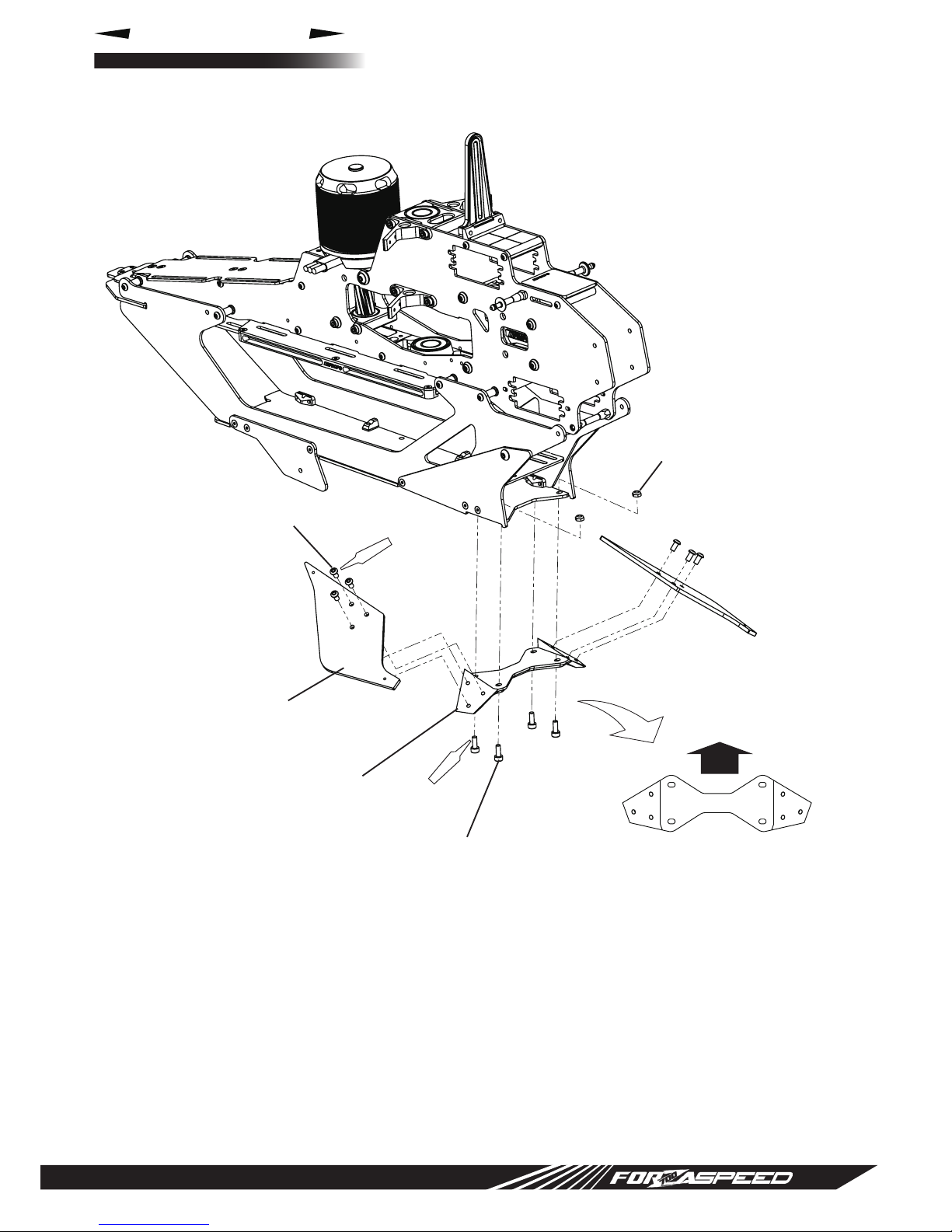
Landing strut adapter 4 Spacer L12 8
Socket head bolt M3 x 8 2 Button head bolt M3 x 20 8
Socket head bolt M2.6 x 5 8
Carbon tray S 1
2-5
Carbon bottom plate 1
Spacer L12 8 Carbon side plate L/R 1 each
Cross member L60 M2.6 2 Landing gear front L/R 1 each
Socket head bolt M2.6 x 5 4 Bottom plate bracket 4
Button head bolt M3 x 20 8 Landing strut adapter 4
Cross member L60 M4 1
Button head bolt M3 x 6 6
Button head bolt M4 x 10 2
Flat head bolt M2.5 x 8 12
Landing strut 2
2-6
Landing gear mount 1
Landing skid 2 Landing gear rear 2
Landing skid cap 4 Socket head bolt M3 x 8 4
Setscrew M4 x 4 4 Nylon lock nut M3 (t2.8) 2
Socket head bolt M3 x 10 4 Button head bolt M3 x 6 6
Main drive gear T112 1
3-1
HG main drive gear T112 1
Flat washer M3 5 HG main gear hub 1
Button head bolt M3 x 8 5 HG tail drive gear T104 1
HG tail gear hub 1
Button head bolt M3 x 6 5
Flat head bolt M2.5 x 6 16
Tail drive gear T104 1 3-2
Servo holding plate 4 4-1 Body absorber plate II 4
Edge protector (50mm) 1
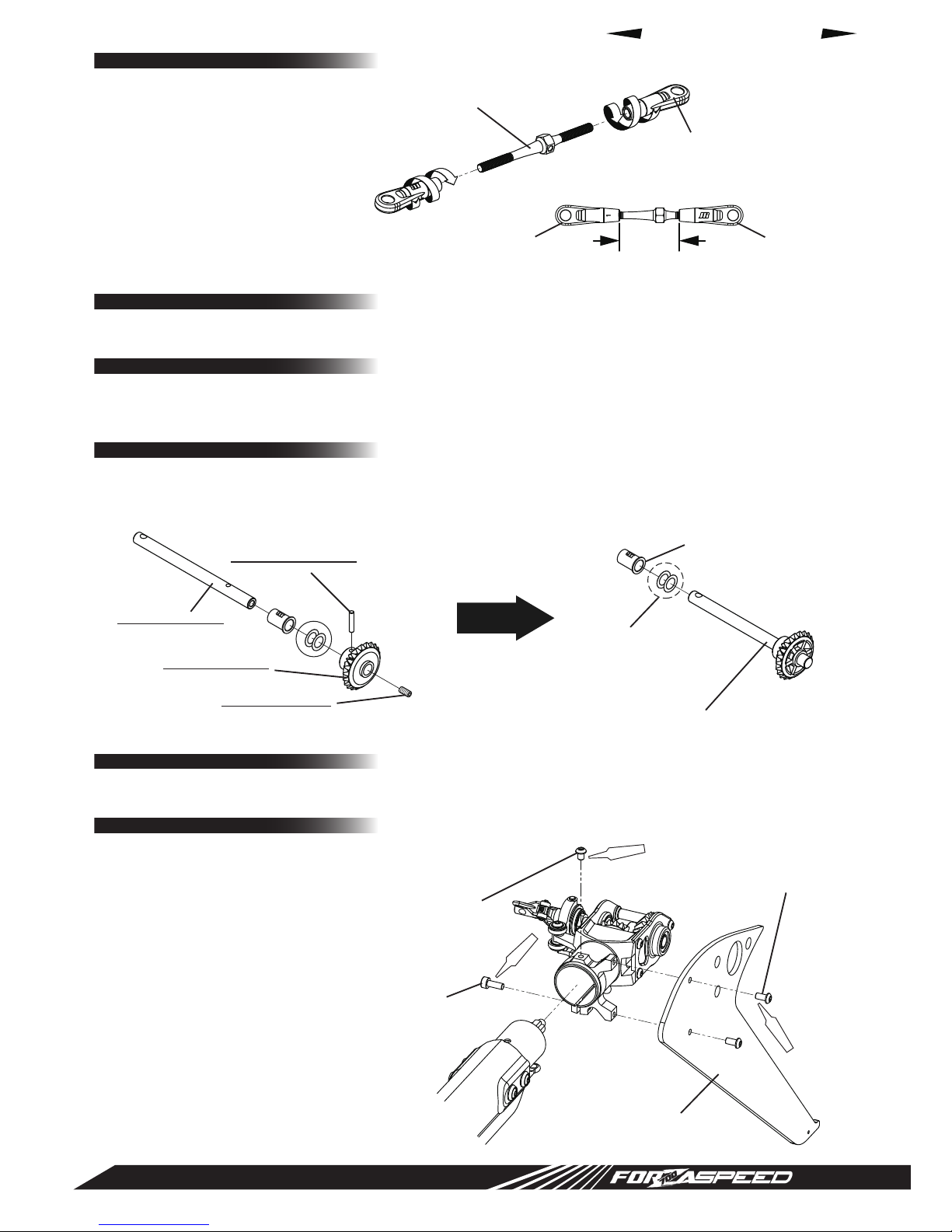
FBL threaded rod L45 2 4-7 Turnbuckle threaded rod L45 2
FRP rear body (Forza 700) 1 5-5 FRP rear body (Forza 700 SPEED) 1
Bevel gear B T22 1
5-6
Rear bevel gear T22 assembly 1
Tail output shaft 1
Bevel gear pin Φ2.3 1
Setscrew M3 x 6 1
Carbon vertical n 1 5-8 Carbon vertical n (Forza 700 SPEED) 1
Carbon tail rotor blade 2 5-9 Carbon tail rotor blade XB92 2
Rubber grommet 2
6-3
Body clip 1
Snap pin 4mm 2 Body clip plate 1
FRP front body (Forza 700) 1 Flat head bolt M3 x 10 2
FRP front body (Forza 700 SPEED) 1

P.3
SPEED MONSTER
1-6_SP
縮尺 1:2
print 2015/08/19
━━━【ASSEMBLY】━━━
━━━【BEFORE COMMENCING ASSEMBLY】━━━
● Standard FORZA 700 assembly manual - Page 2 to Page 7 -
These steps are very important for assembling the FORZA 700 SPEED.
Please carefully read and understand each step before commencing assembly.
● Standard FORZA 700 assembly manual - Page 5 Additional items required -
The following items are required for the SPEED. Note they are dierent from the standard FORZA 700.
Motor : 12S / KV500~560 ESC: greater than 160A Battery : 12S 4500mAh~5000mAh
* If your motor has an 8mm motor shaft, JR No.62029 (pinion gear T13 for 8mm motor shaft) is required.
Main rotor blade :700mm~720mm
* Recommended main rotor blades : JR No. 83136 (carbon main rotor blade XB720-F3C)
Assembly procedure 1-5
Pinion gear T11 has been changed to a pinion gear T13.
There is no change to the assembly method. Please refer to the standard FORZA 700 assembly manual.
Assembly procedure 1-6
Bevel gear B T22 has been changed to the metal front bevel gear T22 assembly. Please refer to the gure below.
* Use the supplied poly slider 6 x 9.5 x 0.13 as necessary to eliminate any up-down movement when the metal front bevel
gear T22 assembly is installed.
* Once the tail pinion unit is completed, check for smooth rotation of the bevel gear. If it does not rotate smoothly, then loose
the setscrew M4 x 4 securing the tail pinion gear and while expanding gap 'A' in the gure (between the metal front bevel
gear T22 assembly and the tail pinion gear), secure the setscrew M4 x 4 again. Adjust until you get appropriate backlash.
* Apply silicon grease evenly over the bevel gear.
Assembly procedure 1-1 to 1-4
There is no change to the assembly method. Please refer to the standard FORZA 700 assembly manual.
Setscrew M4 x 4
A
Bevel gear A T22
Tail pinion unit bearing block assembly
Tail pinion unit R
Tail pinion unit L
Tail pinion gear T22
Metal front bevel gear
T22 assembly
Tail pinion gear T22
Socket head bolt M2.6 x 8 (x 2)
Cross member L32 (x 4)
Setscrew M4 x 4 (x 2)
Nylon lock nut M2.6 (x 2)
Poly slider
6 x 9.5 x 0.13
Shielded bearing
6 x 13 x 5 (x 2)
Red
Red
Red
Red
Red
Red
Red
Red
Red
Red
Red
(X1)
(X2)
(X3)
(X4)
(X5)
(X6)
(X7)
(X8)
(X9)
(X11)
Red (X12)
Red (X13)
Red (X14)
Red (X15)
Brg グリス
GreaseUp
Brg グリス
GreaseUp
Red
Red
Red
Red
Red
Red
Red
Red
Red
Red
Red
Red
Red
Red
Red
Red
Red
Red
Red
Red
Red
Red
Red
Red
Red
Red
(X1)
(X2)
(X3)
(X4)
(X5)
(X6)
(X7)
(X8)
(X9)
(X11)
Red (X12)
Red (X13)
Red (X14)
Red (X15)
Brg グリス
GreaseUp
Brg グリス
GreaseUp
Red
Red
Red
Red
Red
Red
Red
Red
Red
Red
Red
Red
Red
Red
Red
Red
Red
Red
Red
Red
Red
Red
Red
Red
Red
Red
(X1)
(X2)
(X3)
(X4)
(X5)
(X6)
(X7)
(X8)
(X9)
(X11)
Red (X12)
Red (X13)
Red (X14)
Red (X15)
Brg グリス
GreaseUp
Brg グリス
GreaseUp
Red
Red
Red
Red
Red
Red
Red
Red
Red
Red
Red
Red
Red
Red
Red
* Use as necessary

P.4
SPEED MONSTER
2-4_SP
縮尺 1:5
print 2015/08/30
Assembly procedure 2-3
Body catch L21 has been changed to a body catch L23.
There is no change to the assembly method. Please refer to the standard FORZA 700 assembly manual.
Assembly procedure 2-4
Referring to the gure below install the carbon lower frame and the carbon tray S to the upper frame that has been previously
assembled.
* Sand the surface of the carbon tray S where it is inserted into the slot of the lower frame and use some CA glue to secure.
* Check if left and right lower frames are correctly installed (parallel) and then rmly tighten the bolts.
Assembly procedure 2-1 to 2-2
There is no change to the assembly method. Please refer to the standard FORZA 700 assembly manual.
Carbon lower frame (x 2)
Spacer L12 (x 8)
Carbon tray S
Button head bolt M3 x 20 (x 8)
Red
Red
Red
Red
Red
Red
Red
Red
Red
Red
Red
(X1)
(X2)
(X3)
(X4)
(X5)
(X6)
(X7)
(X8)
(X9)
(X11)
Red (X12)
Red (X13)
Red (X14)
Red (X15)
Brg グリス
GreaseUp
Brg グリス
GreaseUp
Red
Red
Red
Red
Red
Red
Red
Red
Red
Red
Red
Red
Red
Red
Red
Red
Red
Red
Red
Red
Red
Red
Red
Red
Red
Red
(X1)
(X2)
(X3)
(X4)
(X5)
(X6)
(X7)
(X8)
(X9)
(X11)
Red (X12)
Red (X13)
Red (X14)
Red (X15)
Brg グリス
GreaseUp
Brg グリス
GreaseUp
Red
Red
Red
Red
Red
Red
Red
Red
Red
Red
Red
Red
Red
Red
Red
Red
Red
Red
Red
Red
Red
Red
Red
Red
Red
Red
(X1)
(X2)
(X3)
(X4)
(X5)
(X6)
(X7)
(X8)
(X9)
(X11)
Red (X12)
Red (X13)
Red (X14)
Red (X15)
Brg グリス
GreaseUp
Brg グリス
GreaseUp
Red
Red
Red
Red
Red
Red
Red
Red
Red
Red
Red
Red
Red
Red
Red
CAG
CAG

P.5
SPEED MONSTER
2-5_SP_A
縮尺 1:5
print 2015/08/30
2-5_SP_B
縮尺 1:5
print 2015/08/30
Assembly procedure 2-5
First, refer to the upper gure and install the landing gear front, side plate, landing strut adapter and the cross member L60M4
to the frame. Note that the landing gear front and the carbon side plate have a left and right. Install so the countersunk holes
are to the outside.
Next, refer to the bottom gure and install the carbon bottom plate and the bottom plate bracket. Carefully note the
orientation for the carbon bottom plate.
* Before applying thread lock to the bolts and tightening them rmly, be sure all the parts shown in both gures are correctly
installed.
Landing gear front L
Landing gear front R
Carbon side plate L
Carbon side plate R
Carbon bottom plate
Cross member L60 M4
Button head bolt
M4 x 10 (x 2)
Landing strut adapter (x 4)
Bottom plate bracket (x 4)
Button head bolt M3 x 6 (x 6)
Flat head bolt
M2.5 x 8 (x 4)
Flat head bolt M2.5 x 8 (x 4)
Red
Red
Red
Red
Red
Red
Red
Red
Red
Red
Red
(X1)
(X2)
(X3)
(X4)
(X5)
(X6)
(X7)
(X8)
(X9)
(X11)
Red (X12)
Red (X13)
Red (X14)
Red (X15)
Brg グリス
GreaseUp
Brg グリス
GreaseUp
Red
Red
Red
Red
Red
Red
Red
Red
Red
Red
Red
Red
Red
Red
Red
Red
Red
Red
Red
Red
Red
Red
Red
Red
Red
Red
(X1)
(X2)
(X3)
(X4)
(X5)
(X6)
(X7)
(X8)
(X9)
(X11)
Red (X12)
Red (X13)
Red (X14)
Red (X15)
Brg グリス
GreaseUp
Brg グリス
GreaseUp
Red
Red
Red
Red
Red
Red
Red
Red
Red
Red
Red
Red
Red
Red
Red
Red
Red
Red
Red
Red
Red
Red
Red
Red
Red
Red
(X1)
(X2)
(X3)
(X4)
(X5)
(X6)
(X7)
(X8)
(X9)
(X11)
Red (X12)
Red (X13)
Red (X14)
Red (X15)
Brg グリス
GreaseUp
Brg グリス
GreaseUp
Red
Red
Red
Red
Red
Red
Red
Red
Red
Red
Red
Red
Red
Red
Red
Red
Red
Red
Red
Red
Red
Red
Red
Red
Red
Red
(X1)
(X2)
(X3)
(X4)
(X5)
(X6)
(X7)
(X8)
(X9)
(X11)
Red (X12)
Red (X13)
Red (X14)
Red (X15)
Brg グリス
GreaseUp
Brg グリス
GreaseUp
Red
Red
Red
Red
Red
Red
Red
Red
Red
Red
Red
Red
Red
Red
Red
Red
Red
Red
Red
Red
Red
Red
Red
Red
Red
Red
(X1)
(X2)
(X3)
(X4)
(X5)
(X6)
(X7)
(X8)
(X9)
(X11)
Red (X12)
Red (X13)
Red (X14)
Red (X15)
Brg グリス
GreaseUp
Brg グリス
GreaseUp
Red
Red
Red
Red
Red
Red
Red
Red
Red
Red
Red
Red
Red
Red
Red

P.6
SPEED MONSTER
2-6_SP
縮尺 1:5
print 2015/08/30
Assembly procedure 2-6
Install the landing gear mount. Then install the landing gear rear.
Carefully note the orientation for the landing gear rear.
NEX650-507-00 (LandingGearMount)
print 2015/09/16
Landing gear mount
Socket head bolt M3 x 8 (x 4)
Landing gear rear (x 2)
Button head bolt M3 x 6 (x 6)
Nylon lock nut M3 (t2.8) (x 2)
Red
Red
Red
Red
Red
Red
Red
Red
Red
Red
Red
(X1)
(X2)
(X3)
(X4)
(X5)
(X6)
(X7)
(X8)
(X9)
(X11)
Red (X12)
Red (X13)
Red (X14)
Red (X15)
Brg グリス
GreaseUp
Brg グリス
GreaseUp
Red
Red
Red
Red
Red
Red
Red
Red
Red
Red
Red
Red
Red
Red
Red
Red
Red
Red
Red
Red
Red
Red
Red
Red
Red
Red
(X1)
(X2)
(X3)
(X4)
(X5)
(X6)
(X7)
(X8)
(X9)
(X11)
Red (X12)
Red (X13)
Red (X14)
Red (X15)
Brg グリス
GreaseUp
Brg グリス
GreaseUp
Red
Red
Red
Red
Red
Red
Red
Red
Red
Red
Red
Red
Red
Red
Red
* Note the proper orientation
front

P.7
SPEED MONSTER
3-1_SP_A
print 2015/08/28
3-1_SP_A
print 2015/08/28
3-1_SP_B
print 2015/08/21
Assembly procedure 3-1
Referring to the gure, assemble the HG main drive gear and the HG tail drive gear.
Assembly procedure 3-2
Mount the HG main drive gear and the HG tail drive gear that were previously assembled in assembly procedure 3-1 to the
helicopter. There is no change to the assembly method. Please refer to the standard FORZA 700 assembly manual.
* The special socket head bolt M4 x 26 which is used to install the HG tail drive gear can be installed from either direction.
Red
Red
Red
Red
Red
Red
Red
Red
Red
Red
Red
(X1)
(X2)
(X3)
(X4)
(X5)
(X6)
(X7)
(X8)
(X9)
(X11)
Red (X12)
Red (X13)
Red (X14)
Red (X15)
Brg グリス
GreaseUp
Brg グリス
GreaseUp
Red
Red
Red
Red
Red
Red
Red
Red
Red
Red
Red
Red
Red
Red
Red
Red
Red
Red
Red
Red
Red
Red
Red
Red
Red
Red
(X1)
(X2)
(X3)
(X4)
(X5)
(X6)
(X7)
(X8)
(X9)
(X11)
Red (X12)
Red (X13)
Red (X14)
Red (X15)
Brg グリス
GreaseUp
Brg グリス
GreaseUp
Red
Red
Red
Red
Red
Red
Red
Red
Red
Red
Red
Red
Red
Red
Red
Red
Red
Red
Red
Red
Red
Red
Red
Red
Red
Red
(X1)
(X2)
(X3)
(X4)
(X5)
(X6)
(X7)
(X8)
(X9)
(X11)
Red (X12)
Red (X13)
Red (X14)
Red (X15)
Brg グリス
GreaseUp
Brg グリス
GreaseUp
Red
Red
Red
Red
Red
Red
Red
Red
Red
Red
Red
Red
Red
Red
Red
HG main drive gear T112
* Use these shim washers
to eliminate any play
between the upper and
lower drive gears after the
main shaft is installed.
HG main gear hub
Flat head bolt
M2.5 x 6 (x 8)
Flat head bolt M2.5 x 6 (x 8)
Button head bolt M3 x 6 (x 5)
Autorotation sleeve
Shim washer
15 x 19 x 0.2 (x 2)
Autorotation unit
* Note the proper orientation
HG tail drive gear T104
HG tail gear hub

P.8
SPEED MONSTER
工程4-1_SP_A
縮尺 1:5
print 2015/08/19
工程4-1_SP_A
縮尺 1:5
print 2015/08/19
工程4-1_SP_A
縮尺 1:5
print 2015/08/19
工程4-1_SP_A
縮尺 1:5
print 2015/08/19
工程4-1_SP_A
縮尺 1:5
print 2015/08/19
工程4-1_SP_A
縮尺 1:5
print 2015/08/19
4-1_SP_B
縮尺 1:5
print 2015/08/21
4-1_SP_C
print 2015/09/03
Assembly procedure 4-1
There is no change to the installation method of the swash servos A, B and C.
Please refer to the standard FORZA 700 assembly manual 4-1.
Glue the edge protectors onto the four body absorber plate II using CA as shown in the gure.
Install the servo horns and the joint ball screw then mount each servo to the helicopter.
The body absorber plate II are mounted at the same time as the servos are mounted - swash servos B and C are installed with
the body absorber plate II.
All four body absorber plate II are the same shape. Note the proper installation direction.
Assembly procedure 4-2 to 4-6
There is no change to the assembly method. Please refer to the standard FORZA 700 assembly manual.
Red
Red
Red
Red
Red
Red
Red
Red
Red
Red
Red
(X1)
(X2)
(X3)
(X4)
(X5)
(X6)
(X7)
(X8)
(X9)
(X11)
Red (X12)
Red (X13)
Red (X14)
Red (X15)
Brg グリス
GreaseUp
Brg グリス
GreaseUp
Red
Red
Red
Red
Red
Red
Red
Red
Red
Red
Red
Red
Red
Red
Red
Red
Red
Red
Red
Red
Red
Red
Red
Red
Red
Red
(X1)
(X2)
(X3)
(X4)
(X5)
(X6)
(X7)
(X8)
(X9)
(X11)
Red (X12)
Red (X13)
Red (X14)
Red (X15)
Brg グリス
GreaseUp
Brg グリス
GreaseUp
Red
Red
Red
Red
Red
Red
Red
Red
Red
Red
Red
Red
Red
Red
Red
CAG
CAG
8mm
10mm
Body absorber plate II (x 4)
Body absorber plate II (bottom)
Body absorber plate II (upper)
for upper side (x 2)
cut as above
for bottom side (x 2)
Edge protector
Swash servo A
Swash servo A
Swash servo B
Swash servo B
Swash servo C
Swash servo C Socket head bolt M2.6 x 10 (x 8)
Servo mount plate (x 2)
Hex tapping screw
M2.6 x 12 (x 4)
Red
Red
Red
Red
Red
Red
Red
Red
Red
Red
Red
(X1)
(X2)
(X3)
(X4)
(X5)
(X6)
(X7)
(X8)
(X9)
(X11)
Red (X12)
Red (X13)
Red (X14)
Red (X15)
Brg グリス
GreaseUp
Brg グリス
GreaseUp
Red
Red
Red
Red
Red
Red
Red
Red
Red
Red
Red
Red
Red
Red
Red
Servo layout
10mm
8mm

P.9
SPEED MONSTER
5-8_SP
縮尺 1:5
print 2015/08/19
4-7_SP
print 2015/08/31
4-7_SP
print 2015/08/31
Assembly procedure 4-7
The FBL threaded rod L45 has been
changed to a turnbuckle threaded rod L45.
It has a reverse thread on one end.
Screw on the universal links as shown in
the gure, making two sets.
For installation, please refer to the standard
FORZA 700 assembly manual 4-7.
Assembly procedure 5-6
The tail output shaft and the bevel gear B T22 have been changed to pre-assembled (co-molded) assembly.
With this change, some assembly procedures are omitted.
For assembly of the tail gear case, please refer to the standard FORZA 700 assembly manual.
Assembly procedure 5-8
Carbon vertical n has been changed to a SPEED n.
Assembly procedure 5-1 to 5-4
There is no change to the assembly method. Please refer to the standard FORZA 700 assembly manual.
Assembly procedure 5-5
The FRP rear body has been changed to a SPEED body. For installation, please refer to the standard FORZA 700 assembly
manual.
Assembly procedure 5-7
There is no change to the assembly method. Please refer to the standard FORZA 700 assembly manual.
Changed to
Red
Red
Red
Red
Red
Red
Red
Red
Red
Red
Red
(X1)
(X2)
(X3)
(X4)
(X5)
(X6)
(X7)
(X8)
(X9)
(X11)
Red (X12)
Red (X13)
Red (X14)
Red (X15)
Brg グリス
GreaseUp
Brg グリス
GreaseUp
Red
Red
Red
Red
Red
Red
Red
Red
Red
Red
Red
Red
Red
Red
Red
Red
Red
Red
Red
Red
Red
Red
Red
Red
Red
Red
(X1)
(X2)
(X3)
(X4)
(X5)
(X6)
(X7)
(X8)
(X9)
(X11)
Red (X12)
Red (X13)
Red (X14)
Red (X15)
Brg グリス
GreaseUp
Brg グリス
GreaseUp
Red
Red
Red
Red
Red
Red
Red
Red
Red
Red
Red
Red
Red
Red
Red
Red
Red
Red
Red
Red
Red
Red
Red
Red
Red
Red
(X1)
(X2)
(X3)
(X4)
(X5)
(X6)
(X7)
(X8)
(X9)
(X11)
Red (X12)
Red (X13)
Red (X14)
Red (X15)
Brg グリス
GreaseUp
Brg グリス
GreaseUp
Red
Red
Red
Red
Red
Red
Red
Red
Red
Red
Red
Red
Red
Red
Red
Tail output shaft
Bevel gear pin Φ2.3
Bevel gear B T22
Setscrew M3 x 6 Rear bevel gear T22 assembly
Button head bolt M3 x 6 (x 2)
Button head bolt M3 x 4
Socket head bolt M3 x 8
Carbon vertical n
(FORZA 700 SPEED)
Poly slider
6 x 9.5 x 0.13 (x 2)
Tail output shaft collar
Toward rotor head Toward swash plate 23.5mm
Turnbuckle threaded rod L45 (x 2)
FBL universal link (x 4)
* Use as necessary

P.10
SPEED MONSTER
6-3_SP_B
縮尺 1:5
print 2015/08/21
6-3_SP_B
縮尺 1:5
print 2015/08/21
Assembly procedure 6-3
There is a magnet attached at rear of the front body. Open up when installing, and then click the magnets together.
The canopy rubber grommets press onto the body catch L23. Then slide the body clip onto the carbon bottom plate.
Assembly procedure 6-1 to 6-2
There is no change to the assembly method. Please refer to the standard FORZA 700 assembly manual.
Assembly procedure 5-9
The carbon tail rotor blades (XB105) have been changed to carbon tail rotor blades XB-92.
There is no change to the assembly method. Please refer to the standard FORZA 700 assembly manual.
Assembly procedure 6-4
There is no change to the assembly method. Please refer to the standard FORZA 700 assembly manual.
Body clip
Body clip
Carbon bottom plate
Body clip plate
Flat head bolt M3 x 10 (x 2)
Snap pin 4mm (x 2)
Rubber grommet (x 2)
FRP front body (FORZA 700 SPEED)

P.11
SPEED MONSTER
【ホバリング】
0% スティックポジション 100%
+12°
→
+4°
→
←
−5°
【ホバリング】
ロースティックポジションハイ
0% 出力 100%
50%
↓
【スタント/3D】
ロースティックポジションハイ
0% 出力 100%
80%
↑
【スタント】
0% スティックポジション 100%
+10°
→
+3°
→
←
−8°
【スピード】
0% スティックポジション 100%
+10°~+13°→
←
−5°
【ホバリング】
0% スティックポジション 100%
+12°
→
+4°
→
←
−5°
【ホバリング】
ロースティックポジションハイ
0% 出力 100%
50%
↓
【スタント/3D】
ロースティックポジションハイ
0% 出力 100%
80%
↑
【スタント】
0% スティックポジション 100%
+10°
→
+3°
→
←
−8°
【スピード】
0% スティックポジション 100%
+10°~+13°→
←
−5°
【ホバリング】
0% スティックポジション 100%
+12°
→
+4°
→
←
−5°
【ホバリング】
ロースティックポジションハイ
0% 出力 100%
50%
↓
【スタント/3D】
ロースティックポジションハイ
0% 出力 100%
80%
↑
【スタント】
0% スティックポジション 100%
+10°
→
+3°
→
←
−8°
【スピード】
0% スティックポジション 100%
+10°~+13°→
←
−5°
Battery Pinion Gear ratio Motor
Pinion : Main KV value
12 cell T13 8.62 : 1 500~560
Rotor RPM
Hovering Stunt SPEED
1,500 ~ 1,600 rpm 2,000~2,100 rpm 2,400~2,500 rpm
Low pitch Intermediate pitch High pitch
Reference pitch -13° 0° +13°
Hovering -5° +4° +12°
Stunt -8° +3° +10°
SPEED -5° ── +10°~ +13°
Pitch curve
━━━【ADJUSTMENT ・ OTHERS】━━━
● Installation of battery and ESC
Refer to the standard FORZA 700 assembly manual page 32 for battery mount and wiring.
● Gear ratio and rotor RPM setup
The gear ratio is dierent from the standard FORZA 700. With this change, rotor RPM and ight time are also dierent from
the standard FORZA 700 as shown in the table below. This SPEED model does not use a standard gear ratio - it is designed
for SPEED. Because of this, the loads on the motor, ESC and battery are large. Flight times will therefore be shorter than
anticipated.
Keeping these things in mind, please refer to the standard FORZA 700 assembly manual page 33.
● Servo neutral adjustment
Refer to the standard FORZA 700 assembly manual page 38.
● Setting and adjustment of the transmitter
Rotor pitch adjustment and pitch curve recommendations have been changed as follows. In SPEED mode, be careful not to
exceed +13 degrees of pitch. Also, as you test y the model, slowly work toward this pitch value. Sudden application of pitch
may over stress the ESC or motor because of high current draw and heat generation. Start with +10 degrees of pitch, and check
ESC current draws and temperatures as you gradually increase pitch to +13 degrees.
Other than this, please refer to the standard FORZA 700 assembly manual page 39 and page 40.
● Main rotor blades
To ensure a stability during speed runs, the use of F3C type blades is recommended.
Recommended main rotor blade : JR No. 83136 (carbon main rotor blade XB720-F3C)
* The use of 3D blades is not recommended - they tend to be unstable during speed runs, causing the model to pitch up.
* Do not suddenly apply collective pitch (and be careful during backwards ight) - the supplied tail rotor blades are smaller
than standard FORZA 700, and are not designed for sudden pitch applications.
● Final checks prior to ight, Fine adjustment following test ight, Be sure to read prior to ight
Please carefully read the standard FORZA 700 assembly manual page 40 to page 43.
Stick position
【Hovering】 【Stunt】 【SPEED】
Stick position Stick position

P.12
SPEED MONSTER
EXP L 1 2 3 H Rotor RPM
NORM OFF ON IN 0 7 100 1,500rpm
OUT 47 60 47
THRO ST-1 OFF ON IN 0 0 2,000rpm
Curve OUT 70 70
ST-2 OFF ON IN 0 0 2,500rpm
OUT 100 100
NORM OFF ON IN 0 10 90 100 Hovering
OUT 34 50 86 95
PITCH ST-1 OFF ON IN 0 50 100 Stunt
Curve OUT 20 62 91
ST-2 OFF ON IN 0 100 SPEED
OUT 30 100
SWASH TYPE 3Servo 120°
AILE + 50%
SWASH MIX GAIN ELEV + 50%
PIT. + 50%
EXP INH ACT
━━━【RADIO SETUP INFORMATION 】━━━
For FORZA 700 SPEED, the following setup has been changed from the standard FORZA 700.
Other than that, please refer to the standard FORZA 700 radio setup information.
● Page 3 - Navigating the parameter setup menus ④ -
Because the setup range of the collective pitch has changed, the value to input for the SWASH MIX also changes.
Change the value from PIT.+45% to PIT. +50%.
● Page 9 - Servo neutral adjustment ⑪ -
It says "Display [SWASH MIX] on your radio and turn the [PIT.] number to +45%.".
This also changes to +50% .
● Page 10 - DATA SHEET -
Input these values for [SWASH MIX], [THRO Curve] and [PITCH Curve].
━━━【Place to y the Forza 700 SPEED】━━━
Because the ight speed is really fast (much faster than a standard model), the FORZA 700 Speed requires a large ying area.
Please be sure to y in a safe place where there is plenty of open area.

P.13
SPEED MONSTER
62056
80205
80067
70772
62059
62058
70733
80168
82446
62083
80004
61997
82445
62082
80100
60072
62077
62077
70788
62080
62080
62079
62078
62076
80091
80013
80091
80171
80039
80273
80273
62081
62078
62074
62075
62073 80263
62070
62072
62071
80091
80263
62084
70786
70760
62088
62088
70789
80262
62063
━━━【PARTS LIST】━━━
Only the parts that are changed or added to the FORZA 700 SPEED are describe here.
For unchanged parts, please refer to the standard FORZA 700 assembly manual.
Item # Description Qty. Note
62076 Carbon bottom plate 1
62077 Carbon side plate L/R 1 L/R one each, 80273 x 6, 80171 x 2 included
62078 Landing gear front L/R 1 L/R one each, 80273 x 6 included
62079 Landing gear mount 1
62080 Landing gear rear 2
62081 Bottom plate bracket 2
70788 Cross member L60 M4 1
80013 Socket head bolt M3 x 8 10
80039 Nylon lock nut M3 (t2.8) 10
80091 Button head bolt M3 x 6 10
80171 Button head bolt M4 x 10 10
80273 Flat head bolt M2.5 x 8 10

P.14
SPEED MONSTER
62056
80205
80067
70772
62059
62058
70733
80168
82446
62083
80004
61997
82445
62082
80100
60072
62077
62077
70788
62080
62080
62079
62078
62076
80091
80013
80091
80171
80039
80273
80273
62081
62078
62074
62075
62073 80263
62070
62072
62071
80091
80263
62084
70786
70760
62088
62088
70789
80262
62063
━━━【PARTS LIST】━━━
Item # Description Qty. Note
61997 Pinion gear T13 1 80004 x 2 included
62056 Metal front bevel gear T22 assembly 1 80205 x 1 included
62058 Metal bevel gear T22 1
62059 Tail pinion shaft 1
62063 Rear bevel gear T22 assembly 1
62070 HG main drive gear T112 1
62071 HG main gear hub 1
62072 HG main drive gear set 1 80091 x 5, 80263 x 8 included
62073 HG tail drive gear T104 1
62074 HG tail gear hub 1
62075 HG tail gear set 1 80263 x 8 included
70733 Main shaft collar 1 80067 x 2 included
70760 FBL universal link 4
70772 Bevel gear pin Φ 2.3 2
70786 Turnbuckle threaded rod L45 2 70760 x 4 included
80004 Setscrew M4 x 4 10
80067 Setscrew M3 x 3 10
80091 Button head bolt M3 x 6 10
80168 Setscrew M3 x 6 10
80205 Poly slider 6 x 9.5 x 0.13 10
80263 Flat head bolt M2.5 x 6 10

P.15
SPEED MONSTER
62056
80205
80067
70772
62059
62058
70733
80168
82446
62083
80004
61997
82445
62082
80100
60072
62077
62077
70788
62080
62080
62079
62078
62076
80091
80013
80091
80171
80039
80273
80273
62081
62078
62074
62075
62073 80263
62070
62072
62071
80091
80263
62084
70786
70760
62088
62088
70789
80262
62063
━━━【PARTS LIST】━━━
Item # Description Qty. Note
60072 Rubber grommet 4
62082 Body clip set 1 80100 x 2 included
62083 Carbon vertical n (FORZA 700 SPEED) 1
62084 Carbon tail rotor blade XB92 2
62088 Body absorber plate II 4 Edge protector included
70789 Body catch L23 2 80262 x 2 included
80100 Flat head bolt M3 x 10 5
80262 Snap pin 4mm 10
82445 FRP front body (FORZA 700 SPEED) 1 60072 x 2, 62082 x 1, 80100 x 2 included
82446 FRP rear body (FORZA 700 SPEED) 1

Oct. 2015
FORZA 700 SPEED Supplemental manual Version 1
The product and the contents of these instructions are subject to change without notice due to improvement.
Table of contents
Other JR ProPo Toy manuals
Popular Toy manuals by other brands

Eduard
Eduard MiG-23BN F.O.D. quick start guide

Fisher-Price
Fisher-Price Laugh & Learn Magical Lights Fishbowl instructions

Little Tikes
Little Tikes Real Wooden Train & Table Set Assembly instructions

John Adams
John Adams Golden coin maker manual

Flight Model
Flight Model EDGE-540 50CC Assembly manual

Mega Bloks
Mega Bloks HALO 96853 manual