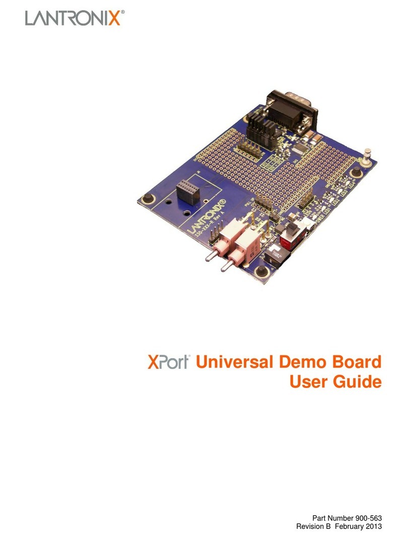
eMagin EMA-200015 User manual

D01-5011
06-01
DSV
G
F
o
DSVGA D
e
G
A D
E
o
r Use wit
h
e
sign Refere
n
E
SIGN
EM
A
h
all eMag
i
USER
’S
n
ce Board Us
e
REFE
R
A
-2000
1
n
DSVGA
O
’S
MA
N
er’s Manual
R
ENC
E
1
5
O
LED Micr
o
N
UAL
E
BOA
o
displays
RD
i

D01-501106-01 DSVGA Design Reference Board User’s Manual
ii
TABLE OF CONTENTS
1.INTRODUCTION..................................................................................................................................1
2.FEATURES..........................................................................................................................................1
2.1.Software Features.........................................................................................................................1
3.SYSTEM REQUIREMENTS & SPECIFICATIONS..............................................................................1
3.1.System Requirements...................................................................................................................1
3.2.DSVGA Mini Design Reference Board .........................................................................................2
4.INTERFACE CONNECTIONS & SETUP.............................................................................................3
4.1.Setup Flow Chart...........................................................................................................................3
4.2.Connect Display to the Design Reference Board .........................................................................3
4.3.Setup PC for Proper Video Output................................................................................................4
4.4.Power Up.......................................................................................................................................4
4.5.Power Down..................................................................................................................................4
4.6.Brightness .....................................................................................................................................5
5.USING THE DSVGA DESIGN REFERENCE BOARD SOFTWARE..................................................6
5.1.DSVGA Design Reference Board Software Utility........................................................................6
5.1.1.Hardware Protocol...............................................................................................................................8
5.3.Downloading New Firmware Versions to the Design Reference Board .......................................9
5.3.1.Using the Firmware Download Utility...................................................................................................9
6.ADVANCED USER INFORMATION..................................................................................................10
6.1.Microcontroller.............................................................................................................................10
6.2.I2C bus.........................................................................................................................................10
6.3.Voltages ......................................................................................................................................10
6.4.Bias Control.................................................................................................................................11
6.5.VCOM Mode................................................................................................................................11
6.6.Gamma........................................................................................................................................11
6.6.1.Gamma Coefficients GC(0-8).............................................................................................................12
6.6.2.Preset Gamma Table descriptions.......................................................Error! Bookmark not defined.
6.6.3.Using “Update LUT” Button for Auto-Gamma Correction...................................................................12
6.6.4.Loading the LUT from a file................................................................................................................13
6.6.5.The “Read LUT” Button......................................................................................................................13
6.6.6.System Gamma.................................................................................................................................13
7.REVISION HISTORY .........................................................................................................................15

D01-501106-01 DSVGA Design Reference Board User’s Manual
iii
List of Figures
Figure 3-1 DSVGA Design Reference Board ................................................................................ 2
Figure 4-1 DRK Setup Flow Chart................................................................................................ 3
Figure 5-1 Firmware download utility........................................................................................... 9

D01-
5
1. I
N
2.
F
2
3.
S
3
5
01106-01
N
TROD
U
The DSV
compact
a
Microdis
p
to evalua
t
included
s
settings f
r
different
t
D
S
D
S
D
S
F
EATU
R
HD
M
USB
i
Supp
o
ON/
O
Softwa
r
.1.
Read
/
fine-t
u
Soft
w
Dow
n
Boar
d
Save
f
S
YSTE
M
System
.1.
For d
i
comp
l
Supp
o
DSVG
A
U
CTIO
N
GA Design
a
nd portabl
e
p
lay. This p
r
t
e and integ
r
s
oftware pa
c
r
om any Wi
n
t
ypes of DS
V
S
VG
A
Mono
c
S
VG
A
Color
O
S
VG
A
Mono
c
R
ES
M
I Video Inp
u
i
nterface all
o
o
rting Soft
w
O
FF power s
w
r
e Feature
s
/
write capab
i
u
ne image c
h
w
are register
n
load and in
s
d
for easy u
p
f
eature stor
e
M
REQUI
Require
m
i
gital RGB i
n
l
iant with th
o
rt software
A
Design Re
f
N
Reference
K
e
means of o
p
r
oduct was
d
r
ate eMagin
c
kage provi
d
n
dows-
b
ase
d
V
GA OLE
D
c
hrome White
O
LED-XL wit
h
c
hrome Gree
n
u
t
o
ws access
t
are (Windo
w
w
itch
s
i
lities allow
h
aracteristi
c
control ove
r
s
tall new fir
m
p
grades and
e
e
s custom re
g
REMEN
m
ents
n
puts: A P
C
e DVI or H
D
requires a
W
erence Boar
d
K
it (EMA-2
0
p
erating an
d
d
esigned to
d
DSVGA mi
d
es access t
o
d
PC throug
h
D
Microdisp
l
OLED-XL w
i
h
glass cove
r
n
OLED-XLT
w
t
o microdisp
w
s)
adjustment
s
c
s
r
the microd
i
m
ware files
e
xpanded fu
n
g
ister settin
g
TS & S
P
C
capable of
p
D
MI standa
r
W
indows PC
d
User’s Man
0
0015) prov
i
d
testing an
e
d
eliver a co
m
crodisplays
o
the microd
i
h
a USB po
r
l
ays:
i
th glass cov
e
r
with glass co
p
lay register
s
s
of microdi
s
i
splay’s bri
g
into your D
S
u
nctionality
g
s for conve
n
P
ECIFI
C
p
roducing a
r
d.
with a US
B
ual
i
des the use
r
e
Magin DS
V
m
plete tool
f
into new pr
o
i
splay’s on-
b
r
t and suppo
r
e
r
o
ver
s
s
play regist
e
g
htness
S
VGA Desi
g
n
ience
C
ATION
S
digital vide
B
port
r
with a
V
GA OLED
f
or develope
r
o
ducts. The
b
oard regist
e
r
ts all
e
r settings to
g
n Referen
c
S
o output
1
r
s
e
r
c
e

D01-
5
3
T
c
o
d
c
o
O
5
01106-01
DSVG
A
.2.
T
he DSVGA
o
mponents
a
i
splaying vi
d
o
nnected to
O
LED conne
DSVG
A
A
Design R
e
Design Re
fe
a
re labeled
fo
d
eo on the
D
PC, a digita
l
cted to the
d
Fi
gu
A
Design Re
f
e
ference
B
fe
rence Boar
fo
r easier id
e
D
SVGA Des
l
video sour
c
d
isplay conn
e
u
re 3-1
D
SV
G
erence Boar
d
B
oard
d is shown i
e
ntification.
T
ign Referen
c
c
e connecte
d
e
cto
r
.
G
A
D
esi
g
n Re
f
d
User’s Man
i
n figure 3-1
T
he minim
u
ce Board ar
e
d
to HDMI
c
f
erence Board
ual
below. The
u
m requirem
e
: a USB ca
b
c
onnector a
n
major
ents for
b
le directly
nd
a DSVG
A
2
A

D01-
5
4. I
N
4
4
5
01106-01
N
TERF
A
Setup
F
.1.
Conne
c
.2.
The micr
o
b
oard co
n
importan
t
orientati
o
below.
Note: Th
DSVG
A
A
CE CO
F
low Chart
c
t Display
t
o
display co
n
n
nector. Th
e
t
to correctl
y
n. . The Dis
p
e DSVGA
O
A
Design Re
f
NNECT
I
Figure 4-1
D
t
o the Des
i
n
nects to the
e
present ve
r
y
orient the
d
p
lay Carrier
O
LED can
b
erence Boar
d
I
ONS &
S
D
RK Setup Fl
o
i
gn Refere
Design Re
fe
r
sion of the
c
d
isplay. Re
f
board is co
n
b
e dama
g
e
d
d
User’s Man
SETUP
o
w Char
t
e
nce Boar
d
f
erence Boa
r
c
onnector is
f
er to the pic
n
nected as s
h
d
if it is not
c
ual
d
r
d via a 40-p
NOT keye
d
c
ture below
f
h
own in fig
u
c
onnected
p
in boar
d
-to-
d
so it is
f
or the prop
e
u
re 4-2
p
roperl
y
.
3
e
r

D01-
5
L
f
i
4
4
4
5
01106-01
L
ift the disp
i
ngerprint
m
Setup
P
.3.
The
d
60 H
z
PC’s
d
Ensu
r
the di
If yo
u
exter
n
the F
n
for m
o
Power
U
.4.
Set t
h
Power
D
.5.
DSVG
A
Figure 4-
2
lay by its
s
arks on it.
I
P
C for Pro
p
d
efault comp
z
. If you are
u
d
isplay pro
p
r
e that the re
f
s
play speci
fi
u
are using a
n
al monitor.
n
key + a de
s
o
re informa
t
U
p
e power sw
i
D
own
A
Design Re
f
2
Displa
y
Car
r
s
ides and t
a
I
nsert the di
s
p
er Video
O
atible resol
u
u
sing this i
n
p
erties.
f
resh rate to
fi
cation.
laptop PC,
y
This is usu
a
s
ignated fun
t
ion.
i
tch to the O
N
erence Boar
d
r
ier Board Co
n
a
ke care no
t
s
play into th
e
O
utput
u
tion is SV
G
n
put set the
v
set to 60 H
z
y
ou may ne
e
a
lly accompl
ction key. S
N
position.
d
User’s Man
n
nection Orie
n
t
to press
o
e
Design R
e
G
A (800x60
0
v
ideo resolu
t
z
, or other s
u
e
d to export
l
ished throu
g
ee your PC’
ual
n
tation
o
n the glass
e
ference Bo
a
0
) with a ref
r
t
ion for 800
x
u
pported re
fr
the video si
g
g
h a key pre
s
s operation
i
s
li
d
or lea
v
a
rd.
r
esh rate of
x
600 in you
r
fr
esh rate pe
r
g
nal to an
s
s including
i
nstructions
4
v
e
r
r

D01-
5
4
5
01106-01
Set t
h
Brightn
.6.
eMagin s
t
luminanc
e
display t
o
devices,
d
lifetime.
DSVG
A
e power sw
i
ess
t
rongly reco
m
e
necessary
o
its maxim
u
d
riving the
m
A
Design Re
f
i
tch to the O
m
mends th
a
for your ap
p
u
m possible
l
m
icrodisplay
erence Boar
d
FF position.
a
t you drive
t
p
lication. Th
l
ifetime. As
at high bia
s
d
User’s Man
.
t
he microdi
s
h
is will exte
n
OLED mic
r
s
levels will
ual
s
play at the
m
n
d the lifeti
m
r
odisplays a
r
decrease its
m
inimum
m
e of the
r
e emissive
overall
5

D01-
5
5.
U
S
5
5
01106-01
U
SING
T
S
OFTW
A
The DSV
followin
g
Perfo
r
Dow
n
firm
w
conn
e
Read
/
chara
c
infor
m
DSVG
A
.1.
1. Conn
e
2. Conn
e
3. Turn
o
4. Chec
k
POR
T
5. Start
t
numb
DSVG
A
T
HE DS
V
A
RE
GA Design
g
functionali
t
r
m software
n
load and in
s
w
are to upda
t
e
ction
/
write regist
e
c
teristics (s
e
m
ation)
A
Design R
e
e
ct the USB
e
ct the vide
o
o
n the DSV
G
k
under the
P
T
number as
t
he DSVGA
_
er and a scr
e
A
Design Re
f
V
GA DE
S
Reference
B
t
y.
microdispl
a
s
tall new ve
r
t
e or provid
e
e
r values to
t
e
e your micr
o
e
ference
B
cable to the
o
source to t
h
G
A Design
R
P
C’s “Devic
shown belo
w
_
SW
_
V1
_
1
.
e
en should
a
erence Boar
d
S
IGN R
E
B
oard includ
a
y brightnes
s
r
sions of the
e
new functi
o
t
he microdi
s
o
display’s
U
B
oard Soft
w
DSVGA D
e
h
e DSVGA
D
R
eference B
e Manager”
w
:
exe applic
a
a
ppear like t
h
d
User’s Man
E
FERE
N
es a suppor
t
s
adjustmen
t
DSVGA D
e
o
nality usin
g
s
play to con
t
U
ser Specifi
c
w
are Utilit
y
e
sign Refer
e
Design Ref
e
B
oar
d
window to
d
a
tion, enter
t
h
at shown b
e
ual
N
CE BO
A
t
software s
u
t
s
e
sign Refer
e
g
an USB (
R
t
rol various
c
ation for m
o
y
e
nce Boar
d
e
rence Boar
d
d
eter
m
ine s
e
t
he correct
C
e
low:
A
RD
u
ite with the
e
nce Board
R
S-232)
o
re
d
e
rial COM
C
OM Port
6

D01-501106-01 DSVGA Design Reference Board User’s Manual
7
Figure 5-1 DSVGA Design Reference Board Software Utility
6. The application communicates with the PIC on the DSVGA Design Reference
Board.
7. The read/write buttons shown in the “OLED Registers” panel will read/write
the register settings in their corresponding boxes from/to the OLED
microdisplay.
8. The read/write buttons displayed in the “GAMMA GC()” panel will
read/write the values used in generating a Gamma table that resides in the
display
9. The read/write buttons displayed in the “OLED EEPROM” panel will
read/write the values stored in the display’s non-volatile memory.

D01-501106-01 DSVGA Design Reference Board User’s Manual
8
5.1.1. Hardware Protocol
1 stop bit, no parity
9600 baud
No hardware handshake

D01-
5
5
.
5
01106-01
Downl
o
.
2.
Board
The abili
t
the latest
Board fo
r
versions
i
5.2.1.Usi
n
Firmwar
e
and insta
l
hex file f
r
To load
y
1.
2.
3.
4.
DSVG
A
o
ading Ne
w
t
y to downl
o
functionalit
y
r
reprogram
m
i
s included i
n
n
g the Firm
w
e
files can b
e
l
l new firm
w
r
om an eMa
g
y
our firmwa
r
Connect t
h
DSVGA
D
Connect t
h
Connect
y
Start the
D
“Bootloa
d
that belo
w
F
A
Design Re
f
w
Firmwar
e
o
ad new ver
s
y
without h
a
m
ing. A util
i
n
the softw
a
are Downlo
a
e
downloade
w
are version
s
g
in source.
r
e files, foll
o
h
e serial cab
D
esign Refe
r
h
e power ca
b
y
our video s
o
D
SVGA
_
SW
_
d
er” tab at th
w
:
F
i
g
ure 5-1
F
i
r
erence Boar
d
e
Versions
s
ions of the
f
a
ving to sen
d
i
ty that dow
n
a
re package.
a
d Utility
d as hex fil
e
s
make sure
o
w the follo
w
le to the PC
r
ence Board
b
le to the D
S
o
urce to the
D
_
V1
_
1.
e
x
e
e
top of the
r
mware down
lo
d
User’s Man
s
to the De
s
f
irmware en
s
d
your DSV
G
n
loads and i
n
e
s. Before at
t
that you ha
v
w
ing steps:
and to the
R
S
VGA Desi
g
D
SVGA De
e
applicatio
n
form. A wi
n
l
oad utilit
y
ual
s
ign Refe
r
s
ures that y
o
G
A Design
R
n
stalls new
f
t
empting to
v
e received
a
R
S232 conn
e
g
n Referenc
e
sign Refere
n
n
. Select the
n
dow shoul
d
r
ence
o
u will have
R
eference
f
irmware
download
a
firmware
e
ctor on the
e Board.
n
ce Board.
d
appear like
9

D01-
5
6.
A
6
6
6
Volt
a
Vinp
u
(USB
)
V5
V3.3
V2.5
VAN
5
01106-01
5.
6.
7.
A
DVAN
C
Microc
o
.1.
The DSV
microcon
t
Provisio
n
the Micr
o
for additi
o
The main
display.
A
acts as th
e
the defau
l
microcon
t
I
2
C bus
.2.
The micr
o
100 KHz
400 KHz
.
website f
o
V
oltag
e
.3.
The pow
e
several v
o
Table 6-1
ag
e Ra
n
ut
)
+5.
0
5Vo
l
3.3
V
2.5
V
5.0
V
DSVG
A
Click the
“
Note: Th
e
be off wh
i
the DSV
G
your new
When yo
u
should be
g
When the
will run.
C
ED US
E
o
ntroller
GA Design
t
roller. Thi
s
n
s are on the
o
chip PIC18
F
o
nal inform
a
function o
f
A
ll commun
i
e
bus maste
r
l
t settings p
r
t
roller scan
s
o
controller i
clock rate.
T
.
Please ref
e
o
r detailed i
n
e
s
e
r supply se
c
o
ltage regul
a
b
elow desc
ng
e
0
Volts
l
ts ±10% (fixe
d
V
olts ±10% (fi
x
V
olts ±10% (fi
x
V
A
Design Re
f
“
Program”
b
e
power on
t
i
le settin
g
u
G
A Desi
g
n
R
firmware t
u
turn on the
g
in to uploa
d
upload is c
o
E
R INF
O
Reference
B
s
is a CMO
S
circuit boar
d
F
2523 datas
h
a
tion about
t
the microc
o
i
cation is ov
r
. On powe
r
r
ogrammed
i
s
for user in
p
s the bus m
a
T
he maxim
u
e
r to the Phi
l
n
formation.
c
tion of the
D
a
tors, some
o
ribes the vo
l
d
)
x
ed)
x
ed)
erence Boar
d
b
utton to fin
d
t
he DSVG
A
p
y
our do
w
R
eference
B
o
the PIC.
DSVGA D
e
d
.
o
mplete, the
O
RM
A
TI
O
B
oard utilize
S
Flash micr
o
d
for in circ
u
h
eet availa
b
t
he microco
n
o
ntroller is t
o
er the inter
n
r
up the regi
s
i
nto the mic
r
p
ut and mon
i
a
ster and co
m
u
m speed all
o
l
ips I
2
C bus
D
SVGA De
s
o
f which are
l
tages and t
h
Typical
+5Volts
5 Volts
3.3 Volts
2.5 Volts
5.0 Volts
d
User’s Man
d
the hex fil
e
A
Desi
g
n Re
w
nload. Onl
y
B
oard when
e
sign Refer
e
DSVGA D
e
O
N
s a Microch
i
o
controller i
u
it reprogra
m
le from Mi
c
n
troller and
p
o
communic
n
al I
2
C bus a
n
s
ters of the
O
r
ocontroller.
i
tors the OL
m
municatio
n
o
wed for I
2
C
specificatio
n
s
ign Refere
n
e
adjustable
w
h
eir purpose
ual
e
you wish t
e
ference Bo
a
y
turn on t
h
y
ou are re
a
e
nce Board t
h
e
sign Refere
n
i
p PIC18F2
5
i
n a 28 pin p
m
ming. Ple
a
c
rochip Tec
h
p
rogrammi
n
ate with the
n
d the micr
o
O
LED is ini
t
.
After initi
a
ED.
n
occurs at t
h
C
bus comm
u
n
available
o
n
ce Board c
o
w
ith potenti
o
.
Pur
p
Mai
n
LED
DVI
,
OLE
D
1
o install.
a
rd should
h
e power to
a
d
y
to writ
e
h
e hex file
nce Board
5
23
ackage.
a
se refer to
h
nology Inc.
n
g.
OLED
o
controller
t
ialized wit
h
a
lization the
h
e standard
u
nication is
o
n the Phili
p
o
nsists of
o
meters.
p
ose
n
Supply
S, DAC
,
RS232
D
Anode
0
e
h
p
s

D01-
5
VPG
VDD
6
6
6
5
01106-01
-1.8
V
1.8
V
Table 6-1 s
h
Bias C
o
.4.
BIASN:
N
VCOM
M
.5.
VCOM
M
Dimmin
g
Gamm
a
.6.
To comp
e
OLED di
o
linearize
t
correctio
n
The gam
m
p
aramete
r
the windo
There are
section o
f
DSVG
A
V
V
±10% (fixed
)
h
ows the
b
oar
d
o
ntrol
N
ormal boa
r
M
ode
M
ODE:
g
: use regist
e
a
e
nsate for th
e
o
de, the R,
G
t
he pixel res
n
takes plac
e
m
a correctio
n
r
s are set fro
m
ws software
.
multiple wa
y
f
the softwar
e
A
Design Re
f
)
d
’s various po
w
r
d – BIASN
=
e
r VCOM to
e
non-linear
G
and B sig
n
ponse as a
fu
e
in the PIC
m
n
consists of
a
m
the pull-d
o
.
All three c
o
y
s to set the
G
e
is shown b
e
erence Boar
d
-1.8V
1.8V
w
er supplies a
n
=
3 gives the
set brightn
e
dependenc
y
n
als include
fu
nction of t
h
m
icrocontr
o
a
nine segm
e
o
wn menu or
o
lor channels
G
amma usin
e
low.
d
User’s Man
n
d their purpo
s
best results
.
e
ss level in
M
y
of lumina
n
internal ga
m
h
e input vid
e
o
lle
r
.
e
nt piece-wi
s
via register
s
have the sa
m
n
g the windo
w
ual
OLE
D
OLE
D
s
es
.
M
anual mod
e
n
ce on the v
o
m
ma correct
i
e
o signal. T
h
s
e-linear fun
c
s
in the “Ga
m
m
e PWL sha
p
w
s software.
1
D
Bias
D
e
.
o
ltage of the
i
on to
h
is gamma
c
tion whose
m
ma” panel
o
p
e.
The Gamm
a
1
o
n
a

D01-501106-01 DSVGA Design Reference Board User’s Manual
12
Figure 6-5 Gamma Section of the Software
6.6.1.Gamma Coefficients GC(0-8)
The 9 boxes in the Gamma section represent the 9 segment piece-wise-linear
function that defines the gamma curve. These 9 values are used to calculate the
256 element look-up-table (LUT) that is required to transform input video data into a
gamma-corrected data signal for the microdisplay input port. The “Read” button will
retrieve the current 9 values from the microcontroller. The user can change any of the 9
values and see the resulting gamma corrected video by pressing the “Write” button.
6.6.2.Using “Update LUT” Button for Auto-Gamma Correction
The software allows for the immediate update of the gamma tables with the push
of a button, “Update LUT”. This button, located in the center of the software
form, tells the firmware to calculate the Gamma coefficients using the VGN
signal provided by the DSVGA microdisplay. This feature allows the display
gamma to be automatically adjusted for any operating conditions of temperature
and brightness. The firmware calculates the 9 Gamma coefficients and then the
full 256 value lookup table. This lookup table is then loaded, by the firmware,
into the DSVGA Microdisplay.

D01-501106-01 DSVGA Design Reference Board User’s Manual
13
6.6.3.Loading the LUT from a file
The software allows for the loading of the gamma tables from a text file. The
format is as follows;
1
174
396
529
575
583
591
599
607
612
618
.
.
1023
Each of the 256 values is on a separate line. This lookup table is then loaded, by
the firmware, into the display.
6.6.4.The “Read LUT” Button
The software allows for the reading of the full 256 values of the LUT using this
button. The result is displayed in the message box at the bottom of the software.
The user can scroll through all the values or select and save to a text file. These
LUT values are the values before being gray-coded.
6.6.5.System Gamma
The software allows for the overall System Gamma to be set between 0.5 and 2.5
when using the Auto-Gamma feature. This System Gamma can be used to
compensate for the gamma of the input video. For example, if the source video is
gamma corrected to 2 then setting the System Gamma to 1.9 and pressing the
“Set” button will give a better overall gamma response. This does not mean that
there is a 1 to 1 relationship between input gamma and the System Gamma.
Figures 6-6 to 6-8 show the grayscale response for a display at several luminance
settings obtained by using the “Update LUT” feature and the System Gamma set
to 1.

D01-501106-01 DSVGA Design Reference Board User’s Manual
14
Figure 6-6 Luminance Response for Auto Gamma at Low Luminance
Figure 6-7 Luminance Response for Auto Gamma at Typical Luminance
AUTO GAMMA
for Low Luminance
0
5
10
15
20
25
0 50 100 150 200 250 300
GRAYSCALE
LUMINANCE
AUTO
AUTO GAMMA
for Typical Luminance
0
20
40
60
80
100
120
140
160
0 50 100 150 200 250 300
GRAYSCALE
LUMINANCE
AUTO

D01-501106-01 DSVGA Design Reference Board User’s Manual
15
Figure 6-8 Luminance Response for Auto Gamma at High Luminance
7. REVISION HISTORY
Revision Level Date Description
0 10/06/2014 Initial draft
01 3-13-2015 Added commercial DRK part number (EMA-200015)
AUTO GAMMA
for High Luminance
0
50
100
150
200
250
300
0 50 100 150 200 250 300
GRAYSCALE
LUMINANCE
AUTO
Other manuals for EMA-200015
1
Table of contents
Popular Computer Hardware manuals by other brands
Vantec
Vantec UGT-CR945 installation guide
ST
ST STM32W-RFCKIT user manual
Konica Minolta
Konica Minolta SRX-101A Service manual

Teletronics International
Teletronics International 11Mbps Wireless Pcmcia Card user manual
ST
ST X-NUCLEO-OUT02A1 user manual
Lenovo
Lenovo ThinkSystem Heavy Duty Full Depth 42U Rack... user guide
