Sicherheit
VORSICHT! Elektrische Spannung!
Im Innern des Geräts benden sich ungeschützte spannungsführende
Bauteile. Die VDE-Bestimmungen beachten. Alle zu montierenden
Leitungen spannungslos schalten und Sicherheitsvorkehrungen gegen
unbeabsichtigtes Einschalten treffen. Das Gerät bei Beschädigung
nicht in Betrieb nehmen Das Gerät bzw. die Anlage außer Betrieb neh-
men und gegen unbeabsichtigten Betrieb sichern, wenn anzunehmen
ist, dass ein gefahrloser Betrieb nicht mehr gewährleistet ist. Das Gerät
ist ausschließlich für den sachgemäßen Gebrauch bestimmt. Bei jeder
unsachgemäßen Änderung oder Nichtbeachten der Bedienungsanlei-
tung erlischt jeglicher Gewährleistungs- oder Garantieanspruch. Nach
dem Auspacken ist das Gerät unverzüglich auf mechanische Beschä-
digungen zu untersuchen. Wenn ein Transportschaden vorliegt, ist un-
verzüglich der Lieferant davon in Kenntnis zu setzen. Das Gerät darf nur
als ortsfeste Installation betrieben werden, das heißt nur in montiertem
Zustand und nach Abschluss aller Installations- und Inbetriebnahme-
arbeiten und nur im dafür vorgesehenen Umfeld. Für Änderungen der
Normen und Standards nach Erscheinen der Bedienungsanleitung ist
Ekon GmbH nicht haftbar.
Technische Daten
Parameter Wert
Gehäuse Kunststoff
Farbe Grau
Montage Reiheneinbau DIN Schiene
REG Aufbau Einheiten 3 Teilungseinheiten
Abmessungen B x H x T / 54 x 90 x 62 mm
Gewicht 80 g
Versorgungsspannung 24VDC -25% / +30%
Umgebungsluftfeuch-
tigkeit Max. 75% r.F. ohne Betauung
Betriebsdauer 100% 100% ED für Dauerbetrieb ausgelegt
Stromverbrauch max. 50 mA
(typisch. 20 mA @ 24 V DC)
Ausgänge
Analogausgänge: 4 x AO 0 bis 10 V
mit 12 Bit Auösung 0 4.096, AO Max.
10 mA Last kurzschlussfest
Eingänge
Digitaleingänge: 4 x DI Eingangsart
PWM-Eingänge, Max. Eingangsspan-
nung 24 V DC +30%, Eingangsfre-
quenz 500 Hz
Bemessungsstoßspan-
nung 0,5 kV
Schutzgrad IP20
Veschmutzungsgrad 2
Schutzklasse II
Zertifzierungen CE gemäß 2004/108/EG
Sicurezza
ATTENZIONE! Tensione elettrica!
All’interno dell’apparecchio sono presenti componenti sotto tensione non
protetti. Attenersi alle speciche della norma VDE. Scollegare i cavi da
montare dall’alimentazione elettrica e adottare tutte le misure necessarie
per impedire un reinserimento accidentale.Non mettere in funzione
l’apparecchio danneggiato. Spegnere l’apparecchio e/o l’impianto e assi-
curarlo contro il reinserimento accidentale se si sospetta che non possa
più essere garantito un funzionamento sicuro. L’apparecchio deve essere
utilizzato esclusivamente in modo conferme alle normative. In caso die
modiche improprie o mancata osservanza delle istruzioni per l’uso,
decade qualsiasi forma di garanzia. Dopo il disimballaggio, l’apparecchio
deve essere immediatamente controllato per vericare la presenza di
eventuali danni meccanici. In caso di danni da trasporto, informare tem-
pestivamente il fornitore. L’apparecchio deve essere utilizzato unicamente
come installazione ssa, ovvero dopo essere stato montato, al termine di
tutti gli interventi di installazione e di messa in funzione necessari e solo
nel contesto previsto. Ekon srl declina ogni responsabilità per eventuali
modiche delle norme e degli standard intervenute dopo la pubblicazione
delle istruzioni per l’uso.
IT
Descrizione del prodotto
Parametri Valore
Alloggiamento Plastica
Colore Grigio
Montaggio Su guida DIN
Unità su guida DIN 3 unità
Dimensioni L x A x P / 54 x 90 x 62 mm
Peso 80 g
Tensione di alimentazione 24 V CC -25% / +30%
Umidità ambiente Max. 75% U. r. senza condensa
Durata di esercizio 100% 100% ED per il operazione continuo
Consumo energetico mass. 50 mA
(tipica 20 mA @ 24 V CC)
Uscite
uscite digitali: 4 x AO da 0 a 10 V
con risoluzione a 12 bit 0 4.096, AO
max.10 mA carico a prova di corto
circuito
Ingressi
ingressi digitali: 4 x DI di tipo PWM,
max. Tensione di ingresso 24 V CC +
30%, frequenza di ingresso 500 Hz
Tensione impulsiva di
dimensionamento 0,5 kV
Grado di protezione IP20
Grado di inquinamento 2
Classe di protezione II
Certicazioni CE secondo 2004/108 /CE
EN
Product description
Security
CAUTION! Electric voltage!
The device contains unprotected live components. Observe the VDE
regulations. Disconnect the cables to be installed from the power
supply and take safety precautions against accidental switch-on.
In case of damage do not start the device. Unplug the device or the
plant from the power supply and take precautions against accidental
switch-on as soon as you assume that operation of the unit under
safe circumstances is no longer possible. The device is exclusively
intended for appropriate use. Any improper use or non-observance of
the operating instructions invalidates the right to claim under guaran-
tee or warranty. After removing the packaging, check the condition of
the unit to assure there is no mechanical damage. Inform the supplier
immediately in case of transport damage. The unit is designed for
xed installations; this means that it can be used only mounted and
after nishing all further installation and commissioning works, and
only in the foreseen environment. Ekon is not liable for modications
of the applied norms and standards after the publication of the
operating instructions.
Parameters Value
Housing Plastic
Color Gray
Installation DIN rail installation
DIN rail mounting units 3 sub units
Dimensions W x H x L / 54 x 90 x 62 mm
Weight 80 g
Supply voltage 24V DC -25%/+30%
Ambient humidity Max. 75% RH without condensation
Operating time 100% 100% ED for continuous operation
Power consumption max. 50 mA
(typical 20 mA @ 24 V DC)
Outputs
Analogue outputs: 4 x AO 0 to 10 V
with 12-bit resolution, 0 4.096, AO
max. 10 mA load, short-circuit proof
Inputs
Digital inputs: 4 x DI PWM inputs,
max. input voltage 24 V DC + 30%,
input frequency 500 Hz
Rated surge voltage 0.5 kV
Protection class IP20
Degree of pollution 2
Protection class II
Certications
CE according to 2004/108/EG
myGEKKO | Ekon GmbH
St. Lorenznerstraße 2
I-39031 Bruneck
T. +39 0474 551 820
myGEKKO | EKON Vertriebs GmbH
Fürstenrieder Straße 279a
D-81377 München
T. +49 8921 5470711
www.my-gekko.com
A First Class Product of Europe
A company from South Tyrol
GEK.IOS.RIO.AX81
RIOAX8
Extendermodul für REG Einbau
Modulo extender guida DIN
Extender module for DIN-Rail mounting
V1.0 - 2022-08 - MRK.PRB.RIO.AX81
eingetragen im Handelsregister in Bozen mit
Steuer- und Eintragungsnummer IT01637750215
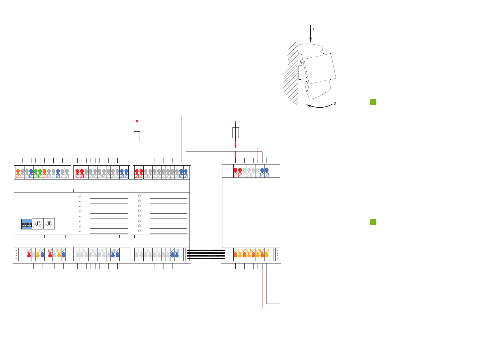
Das myGEKKO RIOAX8 Extendermodul wandelt 4 PWM
Signale in 4 Signale von 0-10V um. Das Modul ist eine
Erweiterung der Module RIO29 und RIO37.
Das RIOAX8-Modul wird über die digitalen Ausgänge
(PWM) des verbundenen RIO-Moduls gesteuert, die in
Verbindung mit einem myGEKKO Gebäuderegler ein
0-10V Signal generieren.
Il modulo di espansione myGEKKO RIOAX8 conver-
te 4 segnali PWM in 4 segnali da 0-10V. Il modulo è
un‘espansione dei moduli RIO29 e RIO37.
Il modulo RIOAX8 viene comandato tramite le uscite di-
gitali (PWM) del modulo RIO connettato, i quali insieme
al controllore myGEKKO generano un segnale da 0-10V.
The myGEKKO RIOAX8 expansion module converts 4
PWM signals in 4 signals of 0-10V. This module is an
expansion of the RIO29 and RIO37 modules.
The RIOAX8 module is controlled by the digital outputs
(PWM) of the connected RIO module, which, in combi-
nation with the myGEKKO controller, generate a 0-10V
signal.
Zum Handbuch
Al Manuale
To the manual
link.my-gekko.com/045
DE
Produktbeschreibung
Dati tecnici Technical data