manuals.online logo
Brands
  1. Home
  2. •
  3. Brands
  4. •
  5. YASKAWA
  6. •
  7. Computer Hardware
  8. •
  9. YASKAWA DI-001 User manual

YASKAWA DI-001 User manual

Yaskawa Electric America, Inc. – www.drives.com
IG.AFD.63, Page 1 of 2
Date: 10/27/05, Rev: 05-10
120VAC Interface Option Card
DI-001
One channel shown as example, remaining channels are identical.
Figure 1. 120VAC Logic Input Option Card
TB3 Drive's I/O terminal
PE
S1 S2 S3 S4 S5 S6 S7 S8
SN SC SP
Switch/Control/PLC
AC Source, 120VAC
Pilot Light
Part Number: DI-001 Kit (UTC000120 or UTC000066 Card)
Applicability: F7, G7
Introduction: The 120VAC Logic Interface option card mounts directly to the
control terminal block on the drive and allows the use of 120VAC control logic
circuits as digital inputs to the drive (S1 - S8). Please check the note on Page 2
regarding power terminal strip interference.
To use all 12 inputs of the G7 (S1 - S12), this card must be used in conjunction
with the DI-003 kit, which covers inputs (S9 - S12). Please refer to the installation guide IG.G7.68 for details.
Receiving: All equipment is tested against defect at the factory. Report any damages or shortages evident when the equipment is
received to the commercial carrier who transported the equipment.
Warning: Hazardous voltage can cause severe injury or death. Lock all power sources feeding the drive and the option card’s
wiring in the “OFF” position.
Important: Before installing this option, a technically qualified
individual, who is familiar with this type of equipment and the
hazards involved, should read this entire installation guide.
Installation and Wiring:
1. Disconnect all electrical power to the drive.
2. Remove the drive’s front cover.
3. Verify that the “CHARGE” indicator lamp inside the drive
is off.
4. Use a voltmeter to verify that the voltage at the incoming
power terminals (L1, L2, L3) has been disconnected.
5. Complete all main circuit terminal connections as the
installation of this board may block wiring access.
6. Complete all field wiring to the option card BEFORE
mounting the card to the drive. Follow this procedure to
prevent damage to the finger terminals of the option card.
7. Connect the Neutral (common) of the command signals to
terminal X2 of the option card.
8. Connect the command signals to the desired inputs of the
option card. See example in Figure 1.
Important: Wires to the option card should be stripped 0.2” ±
20% for maximum system safety. Solder dipping or ferrules
are also highly recommended.
Important: For monitoring the input command signals,
optional pilot lights such as Neon modules can be connected
to the option card’s input terminals. However, their Neutral
MUST be connected to the second (unused) X2 pin to avoid
erroneous operation in case of a wire break.
9. Insert the option card, with its terminal facing up, into
the drive’s I/O terminals S1 thru S8 and tighten all 8
screws.
10. Insert the option card’s P1 wire into the drive’s I/O
terminal SN.
11. Make sure there is a jumper between the drive’s
I/O terminals SC and SP.
12. There are no adjustments to be made to this option
card.
13. Reinstall and secure the drive’s front cover.
14. Place this instruction sheet with the drive’s
technical manual.
Table 1. General Specifications
Inputs: 8 + 2 Neutrals
Input Voltage: 120 VAC ± 15%, 57 - 63Hz
Input Impedance: 19 Kohm
Input Off Current: 4 mA
ON Response Time: 9 ms
OFF Response Time: 32 ms
Table 2. Terminal and Wire Specifications
Terminal
Symbol Terminal
Screw Clamping Torque
Lb-in (N-m) Wire Range
AWG (mm 2)
J1 M3 4.2 to 5.3
(0.5 to 0.6)
26 to 16
(Stranded: 0.14 to 1.5)
(Solid: 0.14 to 1.5)
Yaskawa Electric America, Inc. – www.drives.com
IG.AFD.63, Page 2 of 2
Date: 10/27/05, Rev: 05-10
120VAC Interface Option Card
DI-001
Important: Some drive models manufactured prior to the release of this 120VAC Interface option card may have a power terminal
strip label that will interfere with the installation of the option card. If you have one of the drive models listed in Table 3 with an
interfering power terminal strip label part number, please contact your Yaskawa sales representative and order the corresponding
replacement label listed.
Table 3. Power Terminal Strip Label Specifications
Drive Model:
CIMR-
F7Uxxxx
Drive Model:
CIMR-
G7Uxxxx Interfering Labels Acceptable Labels Replacement Label to Order
for Interfering Label
2022 2018
UNP00074-11 or
NPJT31282 UNP00141-1 or
NPJT31399 UNP00141-1
2030 2022
UNP00075-11 or
NPJT31283 UNP00142-1 or
NPJT31400 UNP00142-1
4022 4018
UNP00075-11 or
NPJT31283 UNP00142-1 or
NPJT31400 UNP00142-1
4030 4022
UNP00075-11 or
NPJT31283 UNP00142-1 or
NPJT31400 UNP00142-1
4037 4030
UNP00076-11 or
NPJT31284 UNP00143-1 or
NPJT31401 UNP00143-1
4045 4037
UNP00076-11 or
NPJT31284 UNP00143-1 or
NPJT31401 UNP00143-1
4055 4045
UNP00076-11 or
NPJT31284 UNP00143-1 or
NPJT31401 UNP00143-1

Other YASKAWA Computer Hardware manuals

YASKAWA VIPA System MICRO User manual

YASKAWA

YASKAWA VIPA System MICRO User manual

YASKAWA VS-616PC5 Series User manual

YASKAWA

YASKAWA VS-616PC5 Series User manual

YASKAWA CPU 013C User manual

YASKAWA

YASKAWA CPU 013C User manual

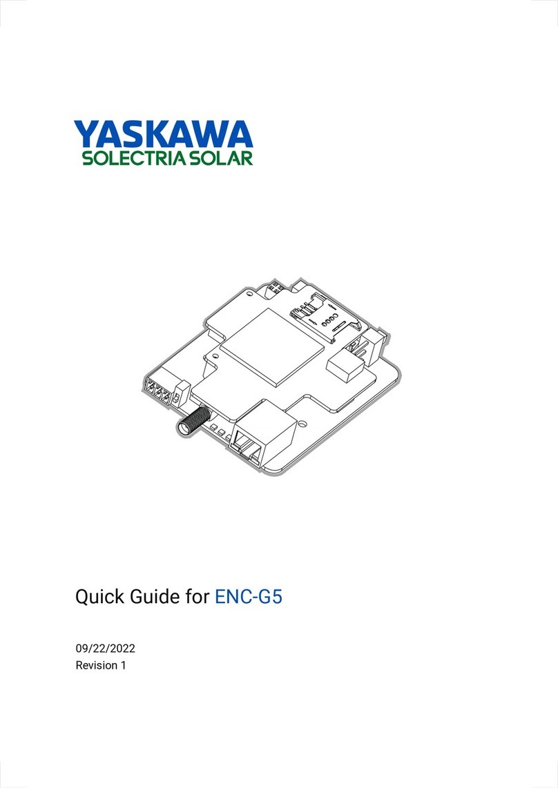
YASKAWA ENC-G5 User manual

YASKAWA

YASKAWA ENC-G5 User manual

YASKAWA PROFIBUS-DP SI-P3 User manual

YASKAWA

YASKAWA PROFIBUS-DP SI-P3 User manual

YASKAWA JANCD-YEW01-E User manual

YASKAWA

YASKAWA JANCD-YEW01-E User manual

YASKAWA VS-616 Series User manual

YASKAWA

YASKAWA VS-616 Series User manual

YASKAWA MOTOMAN DX100 User manual

YASKAWA

YASKAWA MOTOMAN DX100 User manual

YASKAWA VIPA System 300S+ User manual

YASKAWA

YASKAWA VIPA System 300S+ User manual

YASKAWA A1000 Series User manual

YASKAWA

YASKAWA A1000 Series User manual

YASKAWA SK-PID1-L503 User manual

YASKAWA

YASKAWA SK-PID1-L503 User manual

YASKAWA VIPA System 300S+ User manual

YASKAWA

YASKAWA VIPA System 300S+ User manual

YASKAWA VIPA System MICRO M13-CCF0000 User manual

YASKAWA

YASKAWA VIPA System MICRO M13-CCF0000 User manual

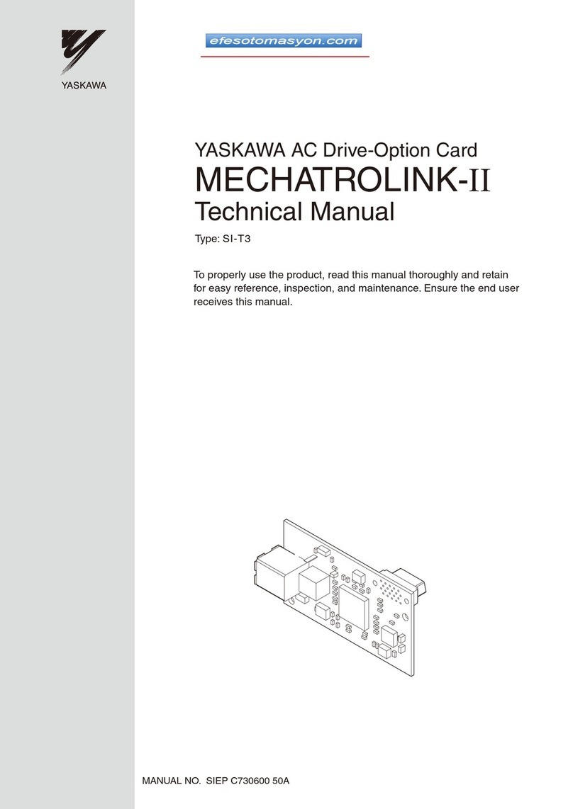
YASKAWA SI-T3 MECHATROLINK-II A1000 Series User manual

YASKAWA

YASKAWA SI-T3 MECHATROLINK-II A1000 Series User manual

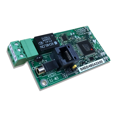
YASKAWA LonWorks SI-W3 User manual

YASKAWA

YASKAWA LonWorks SI-W3 User manual

YASKAWA PG-Z2 User manual

YASKAWA

YASKAWA PG-Z2 User manual

YASKAWA CP 040 RS422/485 User manual

YASKAWA

YASKAWA CP 040 RS422/485 User manual

YASKAWA SI-P1 User manual

YASKAWA

YASKAWA SI-P1 User manual

Popular Computer Hardware manuals by other brands

Roger XM-8DR operating manual

Roger

Roger XM-8DR operating manual

Fantec NVMePCIe TR-1 manual

Fantec

Fantec NVMePCIe TR-1 manual

ekwb EK-FC970 GTX TF5 TFX Series INSTALLATION AND MOUNTING MANUAL

ekwb

ekwb EK-FC970 GTX TF5 TFX Series INSTALLATION AND MOUNTING MANUAL

AEB COBRA AEB510N Fitting Instructions and Warranty Workbook

AEB

AEB COBRA AEB510N Fitting Instructions and Warranty Workbook

YORKVILLE ELITE EP2204 owner's manual

YORKVILLE

YORKVILLE ELITE EP2204 owner's manual

Nortel BayStack 650 install guide

Nortel

Nortel BayStack 650 install guide

Rane Zonetech Firmware update instructions

Rane

Rane Zonetech Firmware update instructions

SSI PRL-1600 Technical manual

SSI

SSI PRL-1600 Technical manual

AuviTran AVY16-ES user manual

AuviTran

AuviTran AVY16-ES user manual

Megawin 8051 user manual

Megawin

Megawin 8051 user manual

ekwb EK-FC 770 GTX DCII INSTALLATION AND MOUNTING MANUAL

ekwb

ekwb EK-FC 770 GTX DCII INSTALLATION AND MOUNTING MANUAL

International Rectifier Photosmart 335 Specifications

International Rectifier

International Rectifier Photosmart 335 Specifications

Analog Devices ADT7473 manual

Analog Devices

Analog Devices ADT7473 manual

e-con Systems See3CAM-81 Application User's Manual

e-con Systems

e-con Systems See3CAM-81 Application User's Manual

EK-Quantum Impulse 120mm FAN user guide

EK-Quantum

EK-Quantum Impulse 120mm FAN user guide

Advantech PCL-746+ user manual

Advantech

Advantech PCL-746+ user manual

ST B-WB1M-WPAN1 user manual

ST

ST B-WB1M-WPAN1 user manual

Motorola M68ICS08AB user manual

Motorola

Motorola M68ICS08AB user manual

manuals.online logo
manuals.online logoBrands
  • About & Mission
  • Contact us
  • Privacy Policy
  • Terms and Conditions

Copyright 2025 Manuals.Online. All Rights Reserved.