Embention Veronte 4 Instructions for use

cod:
Veronte-4-HUM.docx
pag:
1/20
Hardware User Manual
Veronte 4

cod:
Veronte-4-HUM.docx
pag:
2/20
Table of Contents
1. OVERVIEW.....................................................................................................................................5
1.1 OPERATION ....................................................................................................................................5
1.2 PLATFORMS ....................................................................................................................................5
2. SAFETY ..........................................................................................................................................7
3. AIRCRAFT MOUNTING ...................................................................................................................7
3.1 ENCLOSURE ....................................................................................................................................7
3.2 OEM ............................................................................................................................................8
3.3 MECHANICAL MOUNTING .................................................................................................................9
3.3.1 Vibration Isolation ..................................................................................................................9
3.3.2 Location ................................................................................................................................10
3.3.3 Orientation ...........................................................................................................................10
3.4 CONNECTOR LAYOUT ......................................................................................................................10
3.5 MATING CONNECTORS....................................................................................................................11
3.6 ANTENNA INTEGRATION ..................................................................................................................11
3.7 PRESSURE LINES ............................................................................................................................12
4. ELECTRICAL..................................................................................................................................12
4.1 POWER ........................................................................................................................................12
4.2 VERONTE I/O SIGNALS....................................................................................................................13
4.3 HARNESS COLOUR CODE ..................................................................................................................15
4.4 JOYSTICK ......................................................................................................................................16
4.5 OEM BOARD PINOUT.....................................................................................................................18
5. PERFORMANCES..........................................................................................................................20
Figures and Tables
FIGURE 1: VERONTE FCS OVERVIEW.....................................................................................................................6
FIGURE 2: VERONTE AIR .....................................................................................................................................7
FIGURE 3: VERONTE DIMENSIONS (MM) ................................................................................................................8
FIGURE 4: VERONTE OEM DIMENSIONS (MM)........................................................................................................8
FIGURE 5: VERONTE DIMENSIONS (MM) ................................................................................................................9
FIGURE 6: VERONTE MOUNTS .............................................................................................................................9
FIGURE 7: AIRCRAFT AXIS .................................................................................................................................10
FIGURE 8: VERONTE CONNECTORS .....................................................................................................................10
FIGURE 9: 68-PIN REDUNDANT CONNECTOR FOR VERONTE AUTOPILOT (FRONTAL VIEW) ..............................................13
FIGURE 10: FUTABA T10 JOYSTICK .....................................................................................................................17
FIGURE 11: PPM SIGNAL .................................................................................................................................17
FIGURE 12: PPM CONNECTOR...........................................................................................................................17
TABLE 1: VERONTE CONNECTION PANEL...............................................................................................................11
TABLE 2: MATING CONNECTOR TABLE ................................................................................................................11
TABLE 3: ANTENNA INSTALLATION ......................................................................................................................11
TABLE 4: PRESSURE INTAKE CONNECT .................................................................................................................12
TABLE 5: VERONTE I/O INTERFACE .....................................................................................................................15
TABLE 6: COLOUR CODE ...................................................................................................................................16
TABLE 7: OEM BOARD PINOUT ..........................................................................................................................19
TABLE 7: VERONTE PERFORMANCES....................................................................................................................20

cod:
Veronte-4-HUM.docx
pag:
3/20
Acronyms
ADC
Analog to Digital Converter
AWG
American Wire Gauge
CAP
Capture Module
DC
Direct Current
DGPS
Differential GPS
DTS
Digital Transmission System
ECAP
Enhanced CAP
EGNOS
European Geostationary Navigation Overlay Service
EPWM
Enhanced PWM
FCS
Flight Control System
FHSS
Frequency Hopping Spread Spectrum
FTS
Flight Termination System
GIS
Geographical Information System
GND
Ground
GNSS
Global Navigation Satellite Systems
GPS
Global Positioning System
GS
Ground Segment
ISM
Industrial Scientific and Medical
LADGPS
Local Area
LOS
Line of Sight
PWM
Pulse Width Modulation
PWR
Power
RF
Radio Frequency
RS232
Recommended Standard 232
RX
Receiver
SMA
SubMiniature Version A Connector
TX
Transmitter
UAS
Unmanned Aerial System
UAV
Unmanned Aerial Vehicle
cod:
Veronte-4-HUM.docx
pag:
4/20
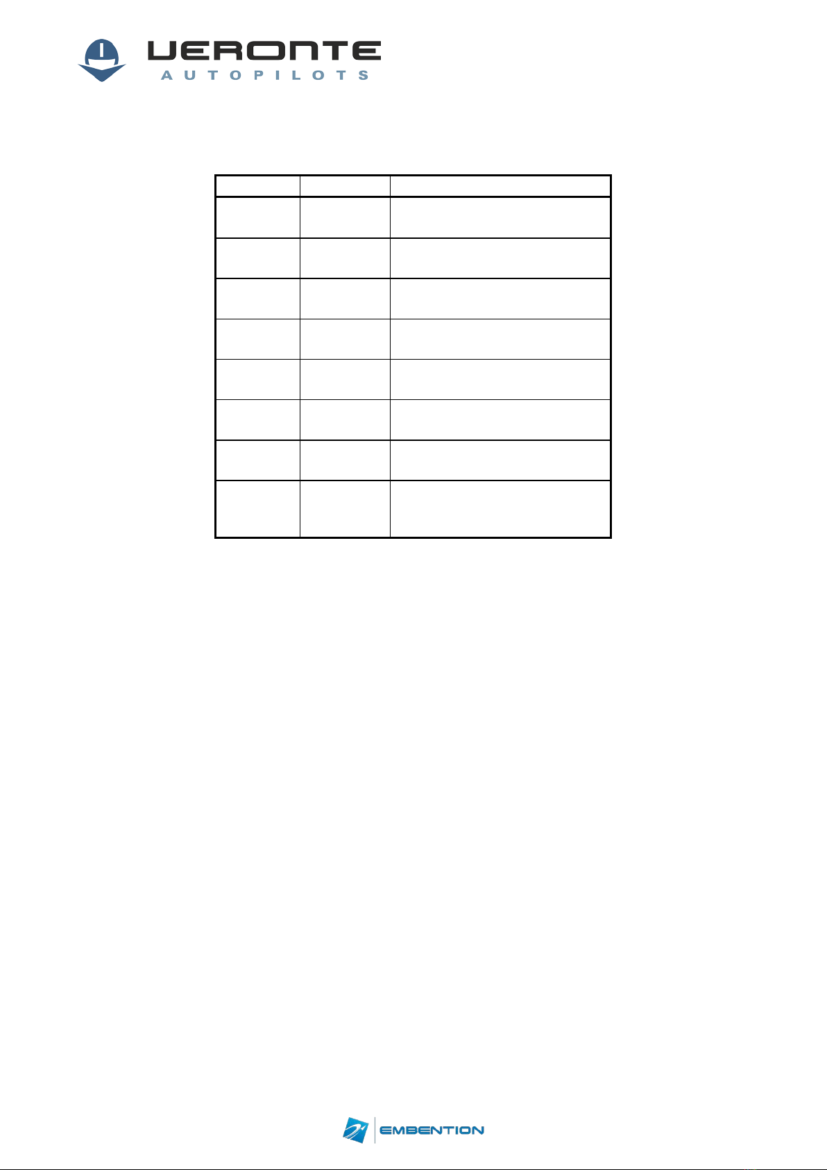
CHANGES RECORD
Issue
Date
Change description
1.0
10/04/2017
Initial Issue document
1.1
15/05/2017
Safety information added
1.2
19/05/2017
Digital inputs voltage range
changed.
1.3
20/09/2017
Mechanical
drawing updated.
1.4
25/09/2017
Table 1 updated
1.5
20/12/2017
Section 4.4 added.
1.6
21/12/2017
Errata correction on section 4.4
1.7
24/05/2018
Power and torque updated.
Colour code added.
OEM pinout updated.

cod:
Veronte-4-HUM.docx
pag:
5/20
1. Overview
Veronte Autopilot is a miniaturized high reliability avionics system for advanced control of
unmanned systems. This control system embeds a state-of-the-art suite of sensors and
processors together with LOS and BLOS M2M datalink radio, all with reduced size and weight.
1.1 Operation
The unique Plug ´n Fly control system, Veronte Autopilot ads fully autonomous control
capabilities to any unmanned system for complete operation, compatible with: UAV, Drone,
RPAS, USV, UGV…
•Highly configurable: Veronte control system is fully configurable; payload, platform
layout, control phases, control channels… even the user interface layout can be user
defined.
•Custom routines:User selectable automatic actions, activated on system event or
periodically.
•Actions: phase change, activate payload, move servo, go to, onboard log, parachute
release…
•Events: waypoint arrival, inside/outside polygon, alarm, variable range, button…
•Telemetry & log: Embedded datalink for system monitoring and telecommand and
customizable user log in both onboard and control station, all with user defined
variables and frequency record.
•External sensor: Support for external sensor connection: magnetometer, radar,
LIDAR, RPM, temperature, fuel level, battery level, weather…
•Payload & Peripheral:Transponder, secondary radios, satcom transceivers, camera
gimbals, motor drivers, photo cameras, flares, parachute release systems, tracking
antennas, pass through RS232 & CAN tunnel...
1.2 Platforms
The Veronte Autopilot is designed to control any unmanned vehicle, either aircraft such as:
multirotors, helicopters, airplanes, VTOL, blimps… as well as ground vehicles, surface vehicles
or many others. Custom flight phases and control channels provide support for any aircraft
layout and performance by using the same software and hardware for: UAS, RPAS, Drone, USV
/ ASV, UGV…

cod:
Veronte-4-HUM.docx
pag:
6/20
Figure 1: Veronte FCS Overview
Veronte contains all the electronics and sensors needed in order to properly execute all the
functions needed to control the UAV. A Veronte-based FCS contains the following elements:
Veronte (Air): it executes in real time all the guidance, navigation and control algorithms
for the carrying airframe, acting on the control surfaces and propulsion system and
processing the signals from different sensors: accelerometers, gyroscopes,
magnetometer, static pressure, dynamic pressure, GPS (EGNOS/Galileo compatible).
Veronte (Ground): apart from linking to other flying Veronte units and supporting manual
and arcade modes with conventional joysticks, it can also control a directional antenna in
order to expand the maximum range. It communicates to Veronte Pipe (software for
ground segment mission management).
Veronte Pipe: software for mission management at the ground segment. It monitors flying
vehicles in real time and can also reproduce past missions in an offline manner. It is also
the graphical user interface where commands and flight plans are produced.

cod:
Veronte-4-HUM.docx
pag:
7/20
2. Safety
Veronte autopilot includes the following features in order to provide your UAS with the best
safety performances:
•Redundant IMU.
•Redundant GPS receiver.
•Redundant Pressure sensor.
•Dual core principal microprocessor + dissimilar safety microcontroller (comicro).
•Independent power supply for main system and safety microcontroller.
In case any malfunction occurs in the principal microprocessor, the comicro can activate
different safety mechanisms by means of 2 digital outputs and 1 serial port (see table 5).
3. Aircraft Mounting
There are two versions of Veronte autopilot: with or without enclosure.
3.1 Enclosure
Veronte is provided using an anodized-aluminium enclosure with enhanced EMI shielding and
IP protection. A high reliability connector is also provided with this version. The total
approximate weight is 190g.
Figure 2: Veronte Air

cod:
Veronte-4-HUM.docx
pag:
8/20
Figure 3: Veronte dimensions (mm)
3.2 OEM
Veronte can be provided in OEM version too. The total approximate weight is 90g.
Figure 4: Veronte OEM dimensions (mm)

cod:
Veronte-4-HUM.docx
pag:
9/20
3.3 Mechanical Mounting
M4 screws are recommended for mounting.
Figure 5: Veronte dimensions (mm)
Vibration Isolation
Although Veronte ultimately rejects noise and high-frequency modes of vibration with
electronic filters and internal mechanical filters, there might be situation where external
isolation components might be needed.
Veronte can be mounted in different ways in order to reject the airframe vibration. The
simplest could be achieved by just using a double-sided foam tape on the bottom side of
Veronte. Other ways may use some external structure which could be rigidly attached to the
airframe and softly attached to Veronte (e.g. foam, silent blocks, αgel, etc…).
Figure 6: Veronte Mounts

cod:
Veronte-4-HUM.docx
pag:
10/20
The user should take into account that wiring should be loose enough so vibrations may not
be transmitted to Veronte.
In cases where Veronte isolation is not viable, it is possible to use soft engine mounts. It is also
recommended when there are other sensible payloads like video cameras or for high vibration
engines.
Location
The location of Veronte has no restrictions. You only need to configure its relative position
with respect to the centre of mass of the aircraft and the GPS antenna. The configuration of
the location of Veronte can be easily configured using Veronte Pipe Software.
Orientation
The orientation of Veronte has no restrictions either. You only need to configure Veronte axes
with respect to the aircraft body axes by means of a rotation matrix or a set of
correspondences between axes. The configuration of the location of Veronte can be easily
configured using Veronte Pipe Software.
Veronte axes are printed on the box and aircraft coordinates are defined by the standard
aeronautical conventions.
Figure 7: Aircraft Axis
3.4 Connector Layout
Figure 8: Veronte Connectors

cod:
Veronte-4-HUM.docx
pag:
11/20
Index Connector
1 LOS SSMA connector
2 GNSS1 SSMA connector
3 M2M SSMA connector
4 GNSS2 SSMA connector
5 Static pressure port (Fitting 5/64in)
6 Dynamic pressure port (Fitting 5/64in)
7 68-pin connector
Table 1: Veronte connection panel
For both pressure ports, mating with clamped 2mm internal diameter flexible tubing is
recommended.
3.5 Mating Connectors
Index Connector Mating Connector
1
RF antenna
(SSMA Jack Female)
SSMA male Plug, low-loss cable is recommended.
2,4 GPS antenna
(SSMA Jack Female)
SSMA male Plug, low loss cable is recommended. Active Antenna GPS: Gain min
15dB (to compensate signal loss in RF Cable) max 50dB, maximum noise figure
1.5dB, power supply 3.3V max current 20 mA
3
M2M antenna
(SSMA Jack Female)
SSMA male Plug, low-loss cable is recommended.
7
Connector
HEW.LM.368.XLNP
Mating connector P/N: FGW.LM.368.XLCT
Mating harness is available on demand.
Table 2: Mating Connector Table
3.6 Antenna Integration
The system uses different kinds of antennas to operate that must be installed on the airframe.
Here you can find some advices for obtaining the best performance and for avoiding antenna
interferences.
Antenna Installation
•Maximize separation between antennas as much as possible.
•Keep it far away from alternators or other interference generators.
•Always isolate antenna ground panel from the aircraft structure.
•Make sure that the antenna is securely mounted.
•Always use high quality RF wires minimising the wire length.
•Always follow the antenna manufacturer manual.
•SSMA connections shall be tightened applying 1Nm of torque.
GPS Antenna
•Antenna top side must point the sky.
•Install it on a top surface with direct sky view.
•Never place metallic / carbon parts or wires above the antenna.
•It is recommended to install it on a small ground plane.
Table 3: Antenna Installation

cod:
Veronte-4-HUM.docx
pag:
12/20
3.7 Pressure Lines
Veronte has two pressure input lines, one for static pressure to determine the absolute
pressure and one for pitot in order to determine the dynamic pressure.
Absolute pressure connection on the aircraft is mandatory while pitot port can be obviated in
some aircrafts. Pitot port absence must be configured on Veronte Pipe software.
Pressure Intake
•Pressure intakes must be located in order to prevent clogging.
•Never install pressure intakes on the propeller flow.
•Design pressure tubing path in order to avoid tube constriction.
Static Pressure
•It is not recommended to use inside fuselage pressure if it is not properly vented.
Pitot Tube
•Pitot tube must be installed facing the airflow in the direction of the “x” axis of the aircraft.
•It is recommended to install it near the aircraft axis in order to avoid false measures during manoeuvres.
•For low speed aircrafts it is recommended at least 6,3mm tubes for preventing rain obstruction.
Table 4: Pressure Intake Connect
4. Electrical
4.1 Power
Veronte can use unregulated DC (6.5V to 36V). Pins used for power and ground are the same
for both Ground and Air configurations.
LiPo batteries between 2S and 8S can be used without regulation needs. Remaining battery
can be controlled by the internal voltage sensor and by configuring the voltage warnings on
the PC application.
For higher voltage installations, voltage regulators must be used. For dimensioning voltage
regulators take into account that a blocked servo can activate regulator thermal protection.
Caution!! Power Veronte out of the given range can cause irreversible damage
to the system. Please read carefully the manual before powering the system.
Veronte and servos can be powered by the same or different batteries. In case there are more
than one battery on the system, a single point ground union it is needed to ensure a good
performance. The ground signal should be isolated from other noisy ground references (e.g.
engines). If all ground need to be connected, connection should be made on the negative pole
of the battery.
It is recommendable to use independent switches for autopilot and motor / actuators. During
the system initialization, PWM signal will be fixed to low level (0V), please make sure that
actuators / motor connected support this behaviour before installing a single switch for the
whole system.
cod:
Veronte-4-HUM.docx
pag:
13/20
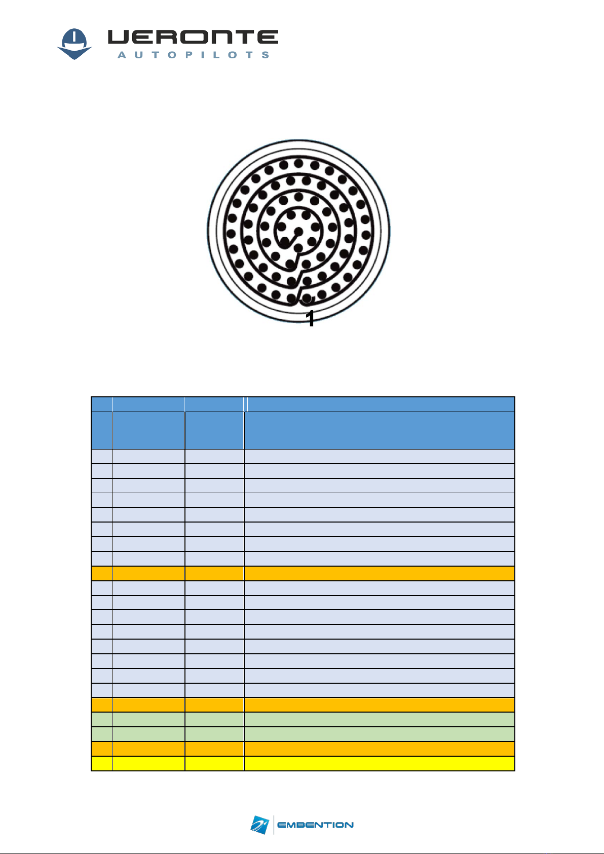
4.2 Veronte I/O Signals
Figure 9: 68-pin redundant connector for Veronte Autopilot (frontal view)
68-PIN CONNECTOR
PIN
SIGNAL
TYPE COMMENTS
1
I/O1
I/O
PWM/DIGITAL OUTPUT/DIGITAL INPUT SIGNAL (0-3.3V)
2
I/O2
I/O
PWM/DIGITAL OUTPUT/DIGITAL INPUT SIGNAL (0-3.3V)
3
I/O3
I/O
PWM/DIGITAL OUTPUT/DIGITAL INPUT SIGNAL (0-3.3V)
4
I/O4
I/O
PWM/DIGITAL OUTPUT/DIGITAL INPUT SIGNAL (0-3.3V)
5
I/O5
I/O
PWM/DIGITAL OUTPUT/DIGITAL INPUT SIGNAL (0-3.3V)
6
I/O6
I/O
PWM/DIGITAL OUTPUT/DIGITAL INPUT SIGNAL (0-3.3V)
7
I/O7
I/O
PWM/DIGITAL OUTPUT/DIGITAL INPUT SIGNAL (0-3.3V)
8
I/O8
I/O
PWM/DIGITAL OUTPUT/DIGITAL INPUT SIGNAL (0-3.3V)
9
GND
GROUND
GROUND SIGNAL FOR ACTUATORS 1-8
10
I/O9
I/O
PWM/DIGITAL OUTPUT/DIGITAL INPUT SIGNAL (0-3.3V)
11
I/O10
I/O
PWM/DIGITAL OUTPUT/DIGITAL INPUT SIGNAL (0-3.3V)
12
I/O11
I/O
PWM/DIGITAL OUTPUT/DIGITAL INPUT SIGNAL (0-3.3V)
13
I/O12
I/O
PWM/DIGITAL OUTPUT/DIGITAL INPUT SIGNAL (0-3.3V)
14
I/O13
I/O
PWM/DIGITAL OUTPUT/DIGITAL INPUT SIGNAL (0-3.3V)
15
I/O14
I/O
PWM/DIGITAL OUTPUT/DIGITAL INPUT SIGNAL (0-3.3V)
16
I/O15
I/O
PWM/DIGITAL OUTPUT/DIGITAL INPUT SIGNAL (0-3.3V)
17
I/O16
I/O
PWM/DIGITAL OUTPUT/DIGITAL INPUT SIGNAL (0-3.3V)
18
GND
GROUND
GROUND SIGNAL FOR ACTUATORS 9-16
19
RS_232_TX
OUTPUT
RS-232 OUTPUT
20
RS_232_RX
INPUT
RS-232 INPUT
21
GND
GROUND
GROUND SIGNAL FOR BUSES
22
ANALOG_4
INPUT
ANALOG INPUT 0-3V

cod:
Veronte-4-HUM.docx
pag:
14/20
23
ANALOG_5
INPUT
ANALOG INPUT 0-3V
24
GND
GROUND
GROUND SIGNAL FOR BUSES
25
CANA_P
I/O
CANbus interface. It supports data rates up to 1 Mbps.
26
CANA_N
I/O
Twisted pair with a 120Ω Zo recommended
27
GND
GROUND
GROUND SIGNAL FOR BUSES
28
CANB_P
I/O
CANbus interface. It supports data rates up to 1 Mbps.
29
CANB_N
I/O
Twisted pair with a 120Ω Zo recommended
30
GND
GROUND
GROUND SIGNAL FOR BUSES
31
I2C_CLK
OUTPUT
CLK LINE FOR I2C BUS
32
I2C_DATA
I/O
DATA LINE FOR I2C BUS
33
GND
GROUND
GROUND FOR 3.3V POWER SUPPLY
34
3.3V
POWER
3.3V-100mA POWER SUPPLY
35
GND
GROUND
GROUND FOR 5V POWER SUPPLY
36
5V
POWER
5V-100mA POWER SUPPLY
37
GND
GROUND
GROUND FOR ANALOG SIGNALS
38
ANALOG_1
INPUT
ANALOG INPUT 0-3V
39
ANALOG_2
INPUT
ANALOG INPUT 0-3V
40
ANALOG_3
INPUT
ANALOG INPUT 0-3V
41
GND
GROUND
GROUND SIGNAL FOR FTS SIGNALS
42
FTS_OUT
OUTPUT
SIGNAL FROM COMICRO TO ACTIVAE SAFETY MECHANISM
(0-3.3V)
43
FTS2_OUT
OUTPUT
SIGNAL FROM COMICRO TO ACTIVAE SAFETY MECHANISM
(0-3.3V)
44
GND
GROUND
GROUND SIGNAL FOR SAFETY BUSES
45
V_ARB_TX
OUTPUT
VERONTE COMICRO UART OUTPUT TO ACTIVATE SAFETY
MECHANISM
46
V_ARB_RX
INPUT
VERONTE COMICRO UART INPUT TO ACTIVATE SAFETY
MECHANISM
47
GND
GROUND
GROUND SIGNAL COMICRO POWER SUPPLY
48
V_ARB-VCC
POWER
VERONTE COMICRO POWER (6.5 to 36V)
49
GND
GROUND
GROUND SIGNAL FOR BUSES
50
OUT_RS485_P
OUTPUT
NON-INVERTED OUTPUT FOR RS-485 BUS
51
OUT_RS485_N
OUTPUT
INVERTED OUTPUT FOR RS-485 BUS
52
IN_RS485_N
INPUT
INVERTED INPUT FOR RS-485 BUS
53
IN_RS485_P
INPUT
NON-INVERTED INPUT FOR RS-485 BUS
54
RS-485_GND
GROUND
GROUND FOR RS-485 BUS
55
EQEP_A
INPUT
ENCODER QUADRATURE INPUT A (0-3.3V)
56
EQEP_B
INPUT
ENCODER QUADRATURE INPUT B (0-3.3V)
57
EQEP_S
INPUT
ENCODER STROBE INPUT (0-3.3V)
58
EQEP_I
INPUT
ENCODER INDEX INPUT A (0-3.3V)
59
GND
GROUND
GROUND FOR ENCODERS
60
V_USB_DP
I/O
VERONTE USB DATA LINE
61
V_USB_DN
I/O
VERONTE USB DATA LINE
62
V_USB_ID
I/O
VERONTE USB ID LINE
63
V_USB_VCC
POWER
VERONTE USB POWER
64
V_USB_VCC
POWER
VERONTE USB POWER
65
GND
GROUND
VERONTE GROUND INPUT

cod:
Veronte-4-HUM.docx
pag:
15/20
66
GND
GROUND
VERONTE GROUND INPUT
67
VCC2
POWER
VERONTE POWER SUPPLY (6.5 to 36V)
68
VCC1
POWER
VERONTE POWER SUPPLY (6.5 to 36V)
Table 5: Veronte I/O interface
4.3 Harness colour code
68-PIN CONNECTOR
PIN
COLOUR
CODE
Description
1
WT
BK
Black
Negro
2
BN
BL
Blue
Azul
3
GN
BN
Brown
Marron
4
YL
GN
Green
Verde
5
GY
GY
Gray
Grís
6
PK
OR
Orange
Naranja
7
BL
PK
Pink
Rosa
8
RD
RD
Red
Rojo
9
BK
VT
Violet
Violeta
10
VT
WT
White
Blanco
11
GY
PK
YL
Yellow
Amarillo
12
RD
BL
13
WT
GN
14
BN
GN
15
WT
YL
16
YL
BN
17
WT
GY
18
GY
BN
19
WT
PK
20
PK
BN
21
WT
BL
22
BN
BL
23
WT
RD
24
BN
RD
25
WT
BK
26
BN
BK
27
GY
GN
28
YL
GN
29
PK
GN
30
YL
PK
31
WT
32
BN
33
GN

cod:
Veronte-4-HUM.docx
pag:
16/20
34
YL
35
GY
36
PK
37
BL
38
RD
39
BK
40
VT
41
GY
PK
42
RD
BL
43
WT
GN
44
BN
GN
45
WT
YL
46
YL
BN
47
WT
GY
48
GY
BN
49
WT
PK
50
PK
BN
51
WT
BL
52
BN
BL
53
WT
RD
54
BN
RD
55
WT
BK
56
BN
BK
57
GY
GN
58
YL
GN
59
PK
GN
60
YL
PK
61
WT
62
BN
63
GN
64
YL
65
GY
66
PK
67
BL
68
RD
Table 6: Colour code
4.4 Joystick
To use the joystick in the system, connect the PPMout of the trainer port to a digital input of
Veronte and configure that digital input as the radio input in Pipe.
If the PPM level is 3.3V, pins 1-8, 10-17 and 55-58 pins can be used.

cod:
Veronte-4-HUM.docx
pag:
17/20
Veronte is compatible with standard Pulse Positon Modulation (PPM) signals, Futaba radios
between 8 and 12 channels are recommended.
Figure 10: Futaba T10 Joystick
Figure 11: PPM Signal
As default, channel 8 is reserved for manual / auto switch. High level is used for automatic
flight and low level for manual control. This channel can be configured on Veronte Pipe.
Caution!! PPM signal must be into the Veronte voltage ranges. Some joysticks
may need an adaptation board, please ask our team to check compatibility.
Veronte connector for CS is provided with 3.5mm stereo plug connector as follows:
Figure 12: PPM connector

cod:
Veronte-4-HUM.docx
pag:
18/20
4.5 OEM Board Pinout
Figure 13: OEM Board
Figure 14: Pinouts for OEM Board
PINOUT
SIGNAL
TYPE COMMENTS
1
LOS SSMA CONNECTOR
2
GNSS1 SSMA CONNECTOR
3
M2M SSMA CONNECTOR
4
GNSS2 SSMA CONNECTOR
5
STATIC PRESSURE PORT (FITTING 5/64IN)
6
DYNAMIC PRESSURE PORT (FITTING 5/64IN)
7C to 28C
GND
GROUND
GROUND SIGNAL
7B
FTS_OUT
O
SIGNAL FROM COMICRO TO ACTIVAE SAFETY
MECHANISM (0-3.3V)
8A
DSPRX_232_D
I
RS-232 INPUT
8B
DSPTX_232_D
O
RS-232 OUTPUT
9
J2
I/O
microUSB CONNECTOR

cod:
Veronte-4-HUM.docx
pag:
19/20
10A
IN_485_P
I
NON-INVERTED INPUT FOR RS-485 BUS
10B
IN_485_N
I
INVERTED INPUT FOR RS-485 BUS
11A
OUT_485_N
O
INVERTED OUTPUT FOR RS-485 BUS
11B
OUT_485_P
O
NON-INVERTED OUTPUT FOR RS-485 BUS
12A
SDA_A_OUT
O
DATA
12B
SCL_A_OUT
O
CLK
13A
CANA_P
I/O
CANbus interface. It supports data rates up to 1 Mbps.
Recommended cable is a twisted pair with a 120Ω Zo.
13B
CANA_N
I/O
14A
ANALIN_1
I
ANALOG INPUT 0-3V
14B
ANALIN_2
I
ANALOG INPUT 0-3V
15A to 27A
PWM1 to
PWM13
I/O
PWM/DIGITAL OUTPUT/DIGITAL INPUT SIGNAL (0-
3.3V)
15B to 27B
V_PWM
I
Servo power (if actuators have an independent
battery)
28A
V_PWM
I
Servo power (if actuators have an independent
battery)
28B
V+
I
6.5 to 36 V
Table 7: OEM board pinout

cod:
Veronte-4-HUM.docx
pag:
20/20
5. Performances
Variable Value
Weight (with enclosure and connector) 190g
Weight (OEM) 90g
Voltage Input 6.5V to 36V
Power Input
5W without M2M
9W with 3.75G M2M
15Wmax with 2G M2M
Minimum Temperature -40ºC
Maximum Temperature +55ºC1
Max. Internal Temperature +85ºC
Minimum Pressure 0kPa
Maximum Pressure 104kPa
Maximum Dynamic Pressure 6kPa 2
Protection Rating IP67 enclosure version
Acceleration Limits (3 axes) ±2g to ±16g 3
Angular Velocity Limits (3 axes) ±125deg/s
to ±2000deg/s4
Magnetic Field Limits (3 axes) ±4 to ±16 Gauss
GPS
72 channels, GPS L1C/A, GLONASS L1OF, BeiDou B1I
Datalink
410 to 480 MHz licensed or FHSS
902-928MHz FHSS
2.4 to 2.483 GHz ISM Band
869.5-869.75 MHz ISM Band
Table 8: Veronte performances
1No convection, ask for increased limits (up to 71ºC)
2Ask for increased limits (up to 50kPa)
3Limit for sustained maneuvers. Transitional higher accelerations are possible (e.g. catapult launch). Ask for increased limits.
4Limit for sustained maneuvers. Transitional higher angular velocities are possible. Ask for increased limits.
Table of contents
Other Embention Autopilot System manuals


Popular Autopilot System manuals by other brands


CUAV
CUAV X7 Plus product manual

Arkbird
Arkbird Autopilot System manual

Raymarine
Raymarine Verado Installation and commissioning

Trio Avionics
Trio Avionics EZ PILOT Operation and installation manual

Dynon Avionics
Dynon Avionics Cessna 172 F-S Installation & maintenance manual

Garmin
Garmin G3X Touch pilot's guide

