Trio Avionics EZ PILOT Specification sheet

EZ PILOT
Operation and Installation Manual
Trio Avionics Corporation
Rev 1.9

Notice and Warnings
Warning: Any failure to comply with the following warnings can lead
to property damage, and serious injury including death.
Although Trio Avionics has taken reasonable steps to test its product, the final determination of safe operation lies
with you, the installer and pilot. Your workmanship in installing, cabling, and testing the autopilot in your airplane is
critical to safety. If you are not the original builder of your aircraft, and do not hold a valid “Repairman’s Certificate”
for your aircraft, you must have the installation done by a qualified A&P aircraft mechanic or the original builder. You
must comply with all current FAA regulations regarding installation of this device in your airplane.
This product is to be used on homebuilt, experimental aircraft only. It is not approved for, nor is it legal to install it in,
certified aircraft. It is not approved by any governmental or non-governmental agency.
Prior to installing or flying this autopilot, read the manual completely. If you have any questions about the installation
or operation of the system, STOP and then call or email Trio Avionics for clarification.
The servo that is a part of this autopilot system is attached directly to your aileron control system. It is possible to
install or adjust it in a manner that may result in improper or unexpected aileron movement that could result in
dangerous aircraft maneuvers. Install it only after you have read and understand the installation instructions. You
must thoroughly inspect and test your installation prior to flight. Mistakes in any modification to your aircraft can be
life threatening!
Each homebuilt aircraft is individual in its construction, maintenance and flying characteristics. Therefore, while
Trio Avionics has tested the product in a variety of aircraft, we do not represent or warrant that it is appropriate or
suitable for use in your particular aircraft. Only you can make that determination and ultimately only you are
responsible for its safe installation and use.
This product is designed for use as an en route navigation aid only, and only at safe altitudes in unobstructed
airspace. It must not be relied upon for any other purpose. It is not to be used for flight in instrument meteorological
conditions (IFR), or approaches into airports in either IFR or visual (VFR) conditions. Power to the servo must be
turned “off” for takeoffs and landings.
In operation, this product relies upon data provided by a GPS receiver. Always keep in mind that GPS signals are
not totally reliable. They may be disrupted by electromagnetic interference, improper placement of antennas, satellite
unavailability and other problems. You must provide data signals from a reliable and properly installed GPS receiver.
The GPS antenna must have a clear “view” of the sky to assure uninterrupted, safe operation. External antennas are
strongly recommended.
When flying an aircraft with this, or any, autopilot enabled, you must be constantly vigilant for any sign of improper
operation of the autopilot. When there is even a suspicion that the autopilot or the GPS receiver is not operating
properly, you must immediately disable the autopilot by any of the various methods detailed in this manual. Do not fly
the autopilot without incorporating the remote servo disconnect switch that is described in this manual.
There may be a tendency to concentrate on the instrument display when test flying this or any other new system in
your aircraft. Do not allow it to distract you from the need to “see and avoid” other aircraft.
The safe practice of aviation demands the consistent exercise of pilot skill, knowledge of airmanship and
weather, judgment and focused attention at a level which is appropriate to the demands of each individual
situation. Pilots who do not possess or exercise the required knowledge, skills and judgment are
frequently injured or killed. Therefore, although an autopilot can serve as a useful navigation aid, no
autopilot can be relied upon and you must be at full attention at all times while flying any aircraft.
If you do not agree to comply with any of the warnings or notices above, do not install or
fly this autopilot system in your aircraft. Call Trio Avionics for a Return Material
Authorization (RMA) and return the unused system for a full refund.

Table of Contents
Page
1.0 Introduction.....................................................................................................................1
2.0 General Information .......................................................................................................2
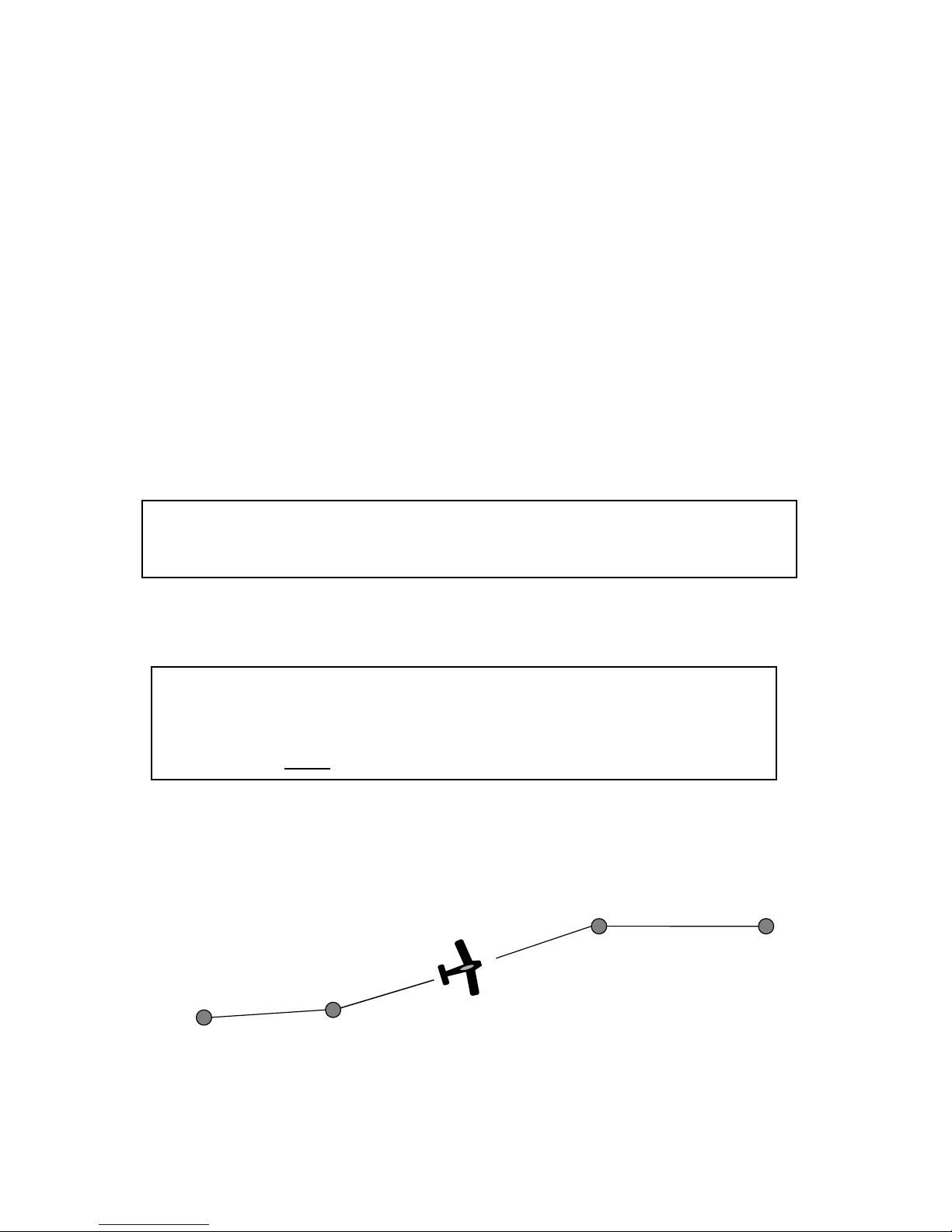
Track Mode (TRK)............................................................................................................2
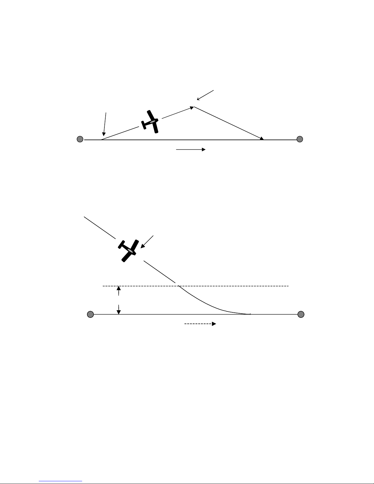
Course Mode (CRS).........................................................................................................3
Intercept Mode (INT) ........................................................................................................3
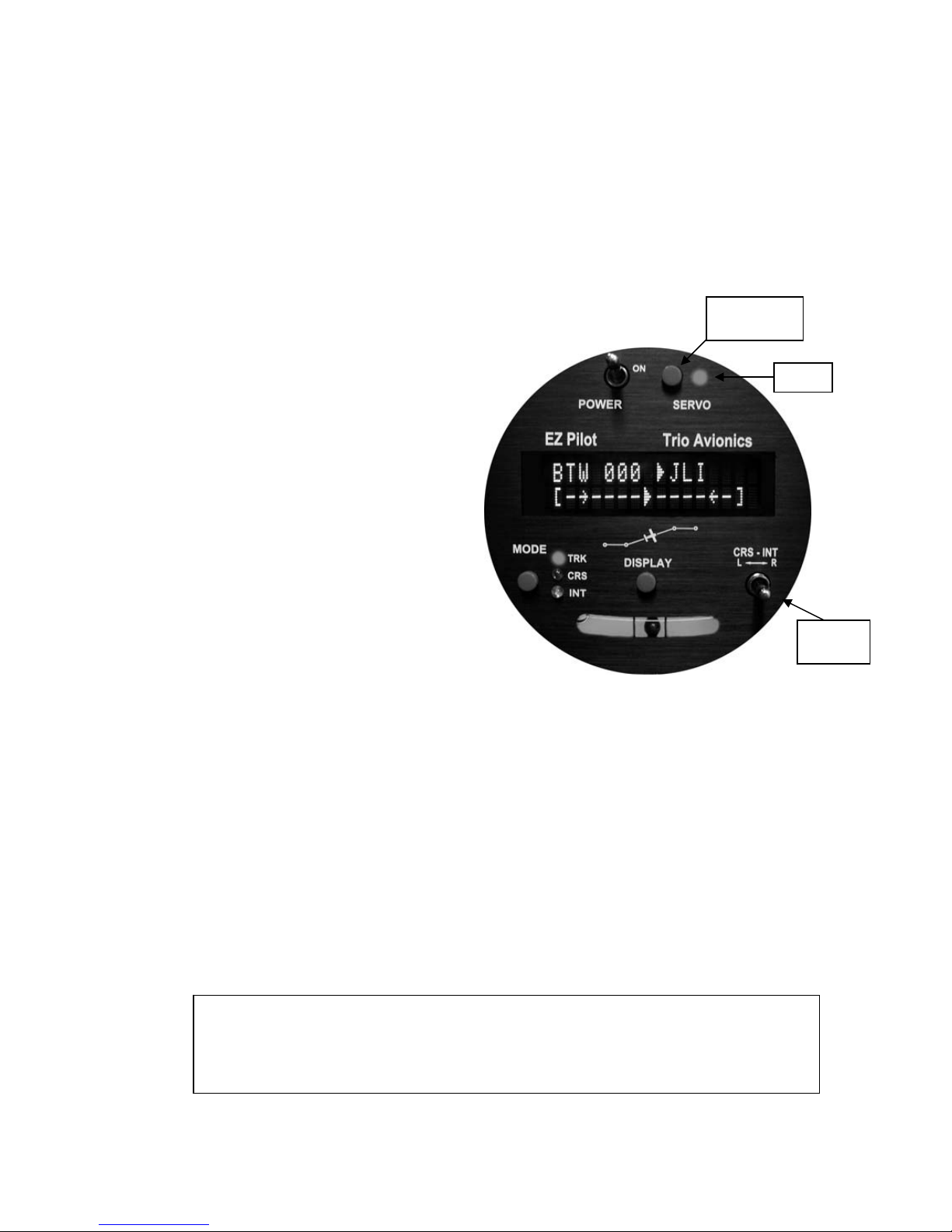
3.0 Control and Display Unit................................................................................................4
3.1 Switch Function and Operation .................................................................................4
3.1.1 On/Off Switch.........................................................................................4
3.1.2 Mode Switch...........................................................................................4
3.1.3 Servo Power Switch...............................................................................5
3.1.4 Display Switch........................................................................................5
3.1.5 Left or Right (L/R) Switch.......................................................................6
3.2 Display Information....................................................................................................7
3.2.1 Power Up Display ..................................................................................7
3.2.2 Initial Logo Screen.................................................................................7
3.2.3 NO GPS Screen.....................................................................................7
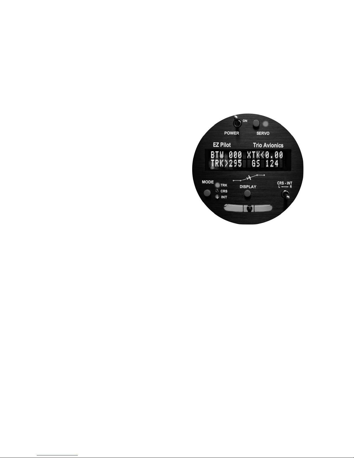
3.2.4 GPS Active, Normal Power-Up Display.................................................8
3.2.5 TRK Mode, GPS Signals Present..........................................................8
3.2.6 TRK Mode, BTW (Bearing to Waypoint field)........................................8
3.2.7 Variable Field, Top Line.........................................................................8
3.2.7.1 XTK (Cross Track Error Field) ..................................................8
3.2.8 TRK (Groundtrack Field)........................................................................9
3.2.9 Variable Fields, Bottom Line..................................................................9
3.2.9.1 GS (Groundspeed)....................................................................9
3.2.9.2 ETE (Estimated Time En-route, HH:MM) .................................9
3.2.9.3 ETe (Estimated Time En-route, MM:SS)................................10
3.2.9.4 RNG (Range to Waypoint)......................................................10
3.2.9.5 Waypoint.................................................................................10
3.2.9.6 Digital Turn Coordinator Display.............................................10
3.2.9.7 DIS?........................................................................................10
3.2.9.8 TRN?.......................................................................................11
3.2.9.9 SPD?.......................................................................................11
3.2.10 CRS (Course) Mode ............................................................................11
3.2.11 INT (Intercept) Mode............................................................................12
3.2.12 TOP (Track Offset Position).................................................................12
3.2.13 Automatic Course Reversal.................................................................13
3.2.14 Variable Display Field – Upper Line.....................................................14
3.2.15 Other Display Presentations................................................................14
4.0 Setup Screens...............................................................................................................14
4.1 Contrast Setting (LCD model only)..........................................................................15
4.2 Initial Servo Position and SERVO direction.............................................................15
4.3 Max Turn Rate selection..........................................................................................15
4.4 IO = Dim or Mode? Screen......................................................................................16
4.5 Circle Last WPT? Screen........................................................................................16
4.6 Turn Rate Display selection (EZ Pilot II only)..........................................................17
4.7 Custom Screen Setup .............................................................................................17
4.8 Software Configuration and Serial Number.............................................................17
5.0 Ground Operation and Flight Example ......................................................................17
5.1 Power Up and Initial Settings ..................................................................................17
5.2 Flying to a Courseline or GOTO Waypoint..............................................................19
5.3 Loss of GPS.............................................................................................................19

5.4 CRS Mode Operation..............................................................................................20
5.5 INT Mode Operation................................................................................................21
5.6 Pilot Controlled Steering (PCS)...............................................................................21
6.0 Installing the Control Head..........................................................................................23
6.1 Your GPS ................................................................................................................23
7.0 Servo ..............................................................................................................................25
7.1 Installing the Servo …………………………………………………………………….25
7.2 Servo Mounting Hardware.....................................................................................26
7.3 Selecting a Site for the Servo ................................................................................27
7.4 Install the Servo Pushrod.......................................................................................28
7.5 Setting Servo Override Force (Slip Clutch)............................................................28
7.6 Adjustment of Servo Rotation Direction and Servo Neutral...................................29
7.6.1 Setup Mode Entry...................................................................................29
7.6.2 Servo Rotation Testing ...........................................................................29
7.6.3 Servo Direction Reversal........................................................................30
7.6.4 Servo Neutral Setting..............................................................................30
7.7 In Flight Adjustment of Servo Neutral....................................................................30
7.8 System Optimization, Flight Time, Distance Counters and Totalizers...................31
7.8.1 System Optimization................................................................................31
7.8.2 Flight Time, Distance and Totalizer Counters (EZ Pilot II only)...............33
7.8.2.1 Flight Time and Distance Counters .........................................33
7.8.2.2 Flight Time and Distance Totalizer Displays............................34
8.0 Electrical Requirements..............................................................................................34
8.1 Primary Input Power...............................................................................................34
8.2 Servo Power...........................................................................................................34
8.3 GPS Data Input......................................................................................................34
8.4 Remote Display Brightness....................................................................................34
8.5 Autopilot Servo Disconnect....................................................................................34
8.6 Wiring Diagram ......................................................................................................35
8.7 J1 Connector Pin Mapping Chart...........................................................................35
9.0 Glossary of Terms.........................................................................................................36
10.0 Contact Information ……………………………………………………………………..36

1
EZ Pilot
1.0 Introduction
Congratulations on choosing the EZ Pilot autopilot. It is designed to enhance the navigational
capabilities of your experimental aircraft and offers many innovative features.
While the EZ Pilot is inherently simple to use, this manual will serve as a guide to understanding
its basic functions and employing its many advanced features. The EZ Pilot is so feature-rich that
mastering it all might seem intimidating at first. Be assured that the advanced features are not
necessary for out-of-the-box utilization of the autopilot and that, except for the fine gain settings
and the servo position adjustment, all of the additional parameters are for increased utilization
and enjoyment of your autopilot. Operation is as simple as entering a flight plan into your
GPS and pressing the SERVO button. The sections on installation and adjustment are placed
toward the back of the manual, as you will not normally need to refer to them once your
installation and test flights are complete.
Section 2 examines the elements of operation employed by the EZ Pilot. Here you will get a feel
of what the unit will do for you, and how to employ its three basic modes of navigation.
Section 3 is a detailed description of the Control and Display unit, which will familiarize you with
switch functions and the wealth of information available to you on the alphanumeric display.
Section 4 is a detailed description of the Setup Screens available to you to configure the
autopilot to meet your preferences and the flight dynamics of your aircraft. This is “must read”
information for the initial set up of the EZ Pilot autopilot.
Section 5 takes you along on a flight, with the EZ Pilot handling the navigational duties. As the
flight progresses, you will begin to employ additional features of the autopilot.
Section 6 describes the installation of the Control Head and some initial tests for proper
operation.
Section 7 is devoted to the installation and operation of the Servo. Because the servo is
connected to your ailerons, be sure you read and thoroughly understand this section before
installing the servo. Paragraph 7.8 describes how to adjust the autopilot so that it is “fine tuned”
to your particular aircraft.
Section 8 covers the electrical requirements and wiring of the EZ Pilot system.
Section 9 is a glossary of terms and acronyms that are used in this manual.
Section 10 provides contact information for those wishing to communicate with Trio Avionics

2
2.0 General Information
The EZ Pilot is a small, solid state aircraft autopilot system designed exclusively for
experimental aircraft and is to be used for VFR operations only. This autopilot is not
certified and is not suitable or approved for installation in a normally certificated aircraft.
The EZ Pilot is a single axis autopilot that controls the roll axis for aircraft attitude correction (wing
leveling) and provides area navigation using signals provided by an external GPS receiver. It is
composed of two units, the control/display unit and the roll servo.
The EZ Pilot does not contain a built-in GPS or other navigation data source. You must supply
an appropriate host GPS source and be correctly connected to the Display Head at the time of
installation. (See the Installation Instructions later in this manual.)
The EZ Pilot uses a solid-state inertial rate sensor for attitude stabilization. It uses elements of
the host GPS digital data stream for the navigation function. It accepts either a NMEA 0183,
V2.XX stream format or the Aviation Link format for navigation guidance.
While the EZ Pilot is an excellent “wing leveler,” it finds its greatest strength following a flight plan
that is active on a host GPS. This can be as simple as a “GOTO” command on the GPS, or a
complex, multi-segment flight plan.
Three navigation modes are provided that allow the pilot to follow a selected GPS course or flight
plan.
1. Track mode (TRK)– used for area navigation tracking a host GPS flight plan (or
GOTO data).
Note: The EZ Pilot also uses the GPS derived information to monitor the inertial sensor performance
and provides automatic corrections to the sensor data to correct for drift due to thermal shifts and
inherent sensor drift and noise errors. The EZ Pilot has a flash based EEPROM memory that is
updated automatically with the most current dynamic calibration information during each flight.
WPT
WPTWPT
WPT
Important Warning
Do not use the autopilot to attempt GPS approaches, even though your GPS may provide
this feature. The EZ Pilot is intended to be an aid to en route navigation only.
The Servo should always be disengaged when initiating the landing checklist at altitude.

3
2. Course mode (CRS) – provides vector navigation as illustrated below. CRS also
allows tracking an autopilot-selected course when the host GPS route function is not in
use. CRS mode uses the GPS signal to provide the aircraft groundtrack. This mode can
be useful for avoiding restricted airspace, weather and oncoming air traffic.
3. Intercept mode (INT)– used to intercept a predefined GPS desired track (DTK) as
illustrated below. The INT mode also uses the GPS signal to provide the aircraft
groundtrack. This mode is useful to regain the original flight plan track after
circumnavigating the previously mentioned flight obstacles.
In both the CRS and INT modes the ground track to be followed may be selected by the pilot,
using either the L/R switch or the PCS steering mode of operation
The EZ Pilot will automatically switch from the INT mode to the TRK mode as it nears the
intercept boundary.
Original GPS course line
Intercept Boundary
Variable distance depending on speed
X
A
utopilot flies INT mode to intercept GPS course
A
s the aircraft nears the GPS course line
the autopilot automatically switches to TRK
WPT WPT
GPS course line
X
A
utopilot flies INT
X
WPT WPT
Pilot commands CRS mode
Pilot commands INT mode “intercept”
Autopilot intercepts original course

4
3. Control and Display Unit
The control and display unit is designed to fit in a standard 3 1/8 inch instrument cutout in the
instrument panel and requires approximately a 3 inch clearance behind the instrument panel.
The unit is powered from the airframe +12V DC system. All controls are located on the front
panel.
This unit contains all of the controls and displays that are required for autopilot mode
selection, display data selection, servo power control, setting CRS direction and INT angle
selection.
3.1 Switch Function and Operation
3.1.1 ON/OFF Switch
The ON/OFF switch controls
application of aircraft power to the EZ
Pilot. In the OFF position the EZ Pilot
is completely disconnected from the
aircraft control system. On power up
the display presents a logo and the
current EZ Pilot firmware code version
(or a customized screen) and sets
several default conditions as follows:
Upon power up the TRK mode is
selected and the
TRK LED is illuminated. This mode is
not fully operational until valid GPS
data is available. When GPS is
unavailable for seven seconds, or after
initial power up, the display will default to a flashing "NO GPS" message. In this
condition the autopilot may still be used to provide a wing leveler function and the L-R
switch can be used to initiate turns to the left or right. Once GPS data is present and
validated, full navigation function is available.
Servo power is initially off on power up. The Servo Power Switch must be pressed
momentarily to activate the system servo for either normal navigation or wing leveler
functions. When the SERVO POWER LED is not illuminated the servo motor is
completely disconnected from the aircraft control system.
3.1.2 Mode Switch
The MODE switch controls the selection of the TRK (track), CRS (course) and INT
(intercept) modes. The default mode during power up is TRK.
Pressing the MODE switch momentarily advances the mode from TRK ---> CRS ---> INT
and then back to TRK. The appropriate LED illuminates in each mode.
The automatic transition from the INT mode to the TRK mode is a function of the
L-R
Switch
LED
The MODE switch also provides the “AUTOMATIC COURSE REVERSAL” feature which does an automatic
servo engage and ground track reversal. Please paragraph 3.2.12 for operation instructions for this feature.
Also, the MODE switch function may be connected to an external switch (in lieu of the display dimming
function) to provide a remote method of changing the EZ Pilot mode setting. See paragraph 4.0 for additional
details.
Push Button
Switch

5
crosstrack error (XTK) magnitude. The unit will sequence automatically from INT to TRK
if the track error magnitude is below approximately 0.5 miles (intercept distance
increases with speed). The precise switching distance is displayed as IDS on the upper
right data field when the INT mode is selected. Also, sequencing the mode from CRS to
INT is not possible if the track error is below this variable limit. (At any time while in the
INT mode the pilot may transition to the TRK mode, or through TRK to CRS mode, by
pressing the MODE switch.)
3.1.3 Servo Power Switch
The servo power switch controls power
application to the EZ Pilot servo. When the
SERVO LED is unlighted servo power is
interrupted. This power interruption
disconnects the EZ Pilot completely from
the control system. When the LED is
illuminated the EZ Pilot is providing servo
power and control signals to the autopilot
servo. The servo is turned on or off
(disconnected) by pressing this switch
momentarily. A remote Servo disconnect
switch should also be mounted on the
aircraft control stick (strongly
recommended). When implemented, this
switch will provide important additional
functionality (PCS mode steering).
3.1.4 Display Switch
The Display Switch performs 6 functions, as follows:
1- Display Data Fields
The DISPLAY switch selects what data is presented on the variable fields of the display.
Momentarily pressing (“bumping”) the display switch advances the lower right line
variable display field through the available selections. Pressing and holding the display
button then toggling the L-R switch advances the upper right variable display field
through its display selections (see function 5 below). The displays available are
described in section 3.2.14.
2 - Display Brightness Control
Display brightness control is also accomplished using the front panel DISPLAY switch or
a remote display dimming switch. Pressing the front panel switch and holding it
approximately one second, then releasing the switch,will change the display brightness
level. The DISPLAY switch should be momentarily released after the next dimming
setting is obtained to prevent cycling to the calibration mode (Function 3 below). The
remote display dimming switch, however, steps the display through the dimming levels
each time it is pressed and will initiate the display scanning mode. (There is an option to
reassign the remote dimming switch to MODE switching but the DISPLAY switch on the
front panel will still perform the dimming function and start or stop the scanning mode.)
3 - Entering “Calibration Mode”
Pressing and holding the DISPLAY switch for more than five seconds causes entry into
the CALIBRATION MODE for fine tuning of the autopilot tracking algorithms (all models)

6
and displaying the FLIGHT TIMERS and TOTAL TIME AND DISTANCE counters (EZ
PILOT II only).
4 - Scan Mode Entry
Pressing the DISPLAY switch rapidly two times in quick succession (double-click) will
cause the variable field data in the right part of the lower line to “scan,” providing a
rotating display of the various GPS data elements being received. The turn coordinator
information is not provided in the “scan” mode; however it is available in the upper right
field (see Function 5 below). Exit from the scan mode is accomplished by double-clicking
the display button again. Whenever the SCAN mode is active a small dot will appear in
the display in front of the data field indicating the SCAN mode is active
5 - Top Line Data Selection
Using the DISPLAY switch in conjunction with the L-R switch allows selection of the data
being displayed in the right side of the top display line.
6 - Setup Screen Entry
If the DISPLAY button is pressed when power is applied, the EZ Pilot will go into the
SETUP mode function. In this mode the following screens and operating parameters can
be changed:
•Contrast adjust (LCD model only),
•Servo position
•Remote dim or mode setting
•Turn rate selection (AUTO, or a fixed turn rate from 1 to 3 deg / sec)
•Last waypoint circle
•Rate of turn display (LARGE or SMALL – EZ Pilot II only)
•Start up screen programming (user programmable)
•System Configuration screen (factory software version and serial number)
3.1.5 Left or Right (L- R) Switch
The L-R switch has 4 functions depending on the EZ Pilot mode.
1 – TOP control
In the TRK mode the L-R switch is used to change the Track Offset Position (TOP)
setting.
2 - Groundtrack Adjustment
In either the CRS or the INT modes the L-R switch is used to select the groundtrack that
the autopilot is commanded to follow. Momentarily moving the L-R switch to the left
slews the commanded groundtrack to the left in one-degree increments. Momentarily
moving the L-R switch to the right causes the commanded groundtrack to be moved to
the right by one degree. Holding the switch in either the left or right position for more
than one second will cause the commanded groundtrack to move right or left at a faster
rate until released.

7
BTW 051 XTK<0.02
TRK
049
KJFK
TRIO AVIONICS
P4EP2
XXXXXXXXX
NO GPS TURN
[--------X-------]
John Anyone
RV
-
6A
N246GK
3 – Drift Correction (NO GPS mode)
Pressing this switch momentarily right or left allows the pilot to adjust roll TRIM either
right or left by one trim count. This is a very fine trim adjustment. If the switch is held for
longer than 1 second in either the right or left position the trim bias count is shifted right
or left at a significantly faster rate until the switch is released. The upper right field in the
display will provide a graphic display of the trim position while the switch is activated and
for about two seconds after the switch is released. If the GPS data to the EZ Pilot is
unavailable, as indicated by a NO GPS warning, the L-R switch provides a method to
turn the airplane to a new heading or stabilize the aircraft in a straight and level attitude.
4 – Changing various parameters
The L-R switch is used in conjunction with the MODE and DISPLAY switches in the
setup and calibration modes to change the various settings. These will be described in
the setup procedures (Section 9) of the manual.
3.2 Display Information
Pilot information for navigation is provided on a high
contrast, bright vacuum fluorescent display (VFD), or
an optional transflective LCD (backlighted). Several
fields on this display are multiplexed (i.e. they use the
same display space to present different information).
This allows the pilot to view all navigation parameters including digital rate of turn information.
The display example shows the normal power up default display with GPS data present.
3.2.1 Power up Display
When the EZ Pilot is powered on a logo display is present showing the firmware revision
operating in the unit. (This can be field programmed to present a personalized screen at
power on) If GPS signals are present on the EZ Pilot interface the display will switch
automatically to the navigation display. If no GPS signals are present the screen will
change to show that NO GPS is being received on the interface.
3.2.2 Initial Logo Screen
The initial factory logo screen shows the
product information including the firmware
revision level and unit serial number in the
extreme right part of the display (represented by the X’s).
Optionally, the purchaser may program their
own personalized logo screen. Each time the
unit is turned on it will display this information.
This information can be field re-programmed
at any time by entering the setup menu screens (section 9).
3.2.3 NO GPS Screen
The “NO GPS” screen will display on power up
if no GPS signal is present or if the GPS signal
is lost for a period exceeding five seconds. In
all cases the navigation display will return to
normal automatically when the GPS signals are reacquired. Note that there may be a
delay of up to seven seconds in restoring the display after a GPS signal becomes active on

8
BTW 025 XTK<0.02
TRK
025
KLAX
the interface. In the event the GPS signal is lost during normal area navigation the "NO
GPS" screen will be made active and the EZ Pilot will go into the wing leveler mode
following a “straight and level” course on the last commanded groundtrack. In this mode,
manual corrections to the dead reckoning track can be made using the electronic trim
feature. (See paragraph 3.1.5)
3.2.4 GPS Active, Normal Power Up Display
On power up, the EZ Pilot defaults to the TRK mode of operation. Once GPS signals
become active on the interface, and a flight plan is entered, the display illustrated below
is presented to the pilot. This display is the power up default presentation. It is possible
to have the displays shown in paragraph 3.2.9.7 (DIS?), paragraph 3.2.9.8 (TRN?) or
paragraph 3.2.9.9 (SPD?) if the conditions noted below are present at that time.
3.2.5 TRK Mode, GPS Signals Present
The diagram on the next page shows the EZ Pilot display immediately after power up
with a good GPS signal present, and flight plan entered. Note that the SERVO POWER
LED is not illuminated. Although the unit is fully capable of providing area navigation, the
SERVO pushbutton must be manually pressed (connected) before the EZ Pilot will take
control of the roll axis of the aircraft.
3.2.6 TRK Mode, BTW (Bearing To Waypoint Field)
The bearing to waypoint (BTW) field is located
on the left side of the top line as illustrated. This
field is updated whenever the GPS data to the
EZ pilot is refreshed, normally once every one or
two seconds, depending on the GPS interface
data rate. (A GPS with NEMA data output
normally updates once every two seconds, while
an Aviation Data Link updates once every
second.) BTW is the exact magnetic bearing
from the current aircraft position to the next GPS
route waypoint. Please note that the line directly
below the BTW data contains the current track
(TRK) information (if these two numbers are
identical, the aircraft is tracking directly to the
destination waypoint regardless of the actual
magnetic heading of the aircraft).
3.2.7 Variable Field, Top Line
The right side of the upper line of the display may be changed to present any data
derived from the GPS available in the bottom line right field (see section 3.2.9) or an
electronic rate of turn display. The factory default display is to present the information
shown below, but the user may wish to otherwise configure this segment. See section 3.1
for details on setting the data to be displayed in this field.
3.2.7.1 XTK (Cross Track Error Field)
The Cross Track Error Field (XTK)
provides a distance measurement in
miles, tenths and hundredths of how
far the aircraft is positioned either right

9
BTW 025 XTK<0.02
TRK
025
KLAX
BTW 025 XTK<0.02
TRK
025
GS
200
BTW 025 XTK<0.02
TRK
025
ETE
2
:
21
or left of the desired track (DTK). The maximum value in this field is 9.99 miles.
A positioning symbol, immediately preceding the numerical data, indicates the
"fly to" direction required to null this error. If this symbol has its apex to the left
(<), the autopilot will fly to the left to eliminate the error. Conversely, if the apex
is to the right (>) the autopilot will fly to the right to eliminate the error. Here the
aircraft is just .02 miles to the right of the desired track, so the autopilot will fly to
the left to resume correct DTK.
3.2.8 TRK (Groundtrack Field)
The groundtrack (TRK) field is located on the
line directly below the “Bearing to Waypoint”
(BTW) field on the extreme left side. The TRK
field is the current track over the earth based
on the GPS updates every one or two seconds.
3.2.9 Variable Fields, Bottom Line
The bottom line, extreme right field is another variable field used to display other tracking
data of interest to the pilot. The possible data fields displayed are:
•GS groundspeed, closure speed to the destination waypoint
•ETE estimated time en-route, in hours and minutes format
•ETe estimated time en-route, in minutes and seconds format
•RNG distance from the current “TO” waypoint
•(WPT) "TO" waypoint identifier *
•(TC) Digital graphic turn coordinator display *
•DIS? Distance tolerance error indicator
•TRN? Turn tolerance error indicator
•SPD? Speed tolerance error indicator
•TOP Track Offset Position indicator
* no associated label field displayed
Each field above except the DIS?, TRN? and SPD? fields is selected by pressing the
DISPLAY switch momentarily. The DIS?, TRN? and SPD? fields are automatically
displayed to indicate GPS data anomalies as described below. The ETE or Ete label
format is selected automatically by the autopilot. The TOP field will not be displayed if
the TOP value is 0.00 (no offset).
3.2.9.1 GS (Groundspeed)
The GS (groundspeed) field indicates
the aircraft speed over the ground in
the units (miles per hour or knots) as
selected on the host GPS system.
This field is limited to a maximum value of 999 miles/knots per hour.
3.2.9.2 ETE (Estimated Time En-route, HH:MM)
The ETE (estimated time en-route)
field shows the time to the current
waypoint based on the closing velocity
(NMEA link only) to the waypoint
(which may be different from the groundspeed GS/distance calculation

10
BTW 025 XTK<0.02
TRK
025
Et
e
14
:
03
BTW 025 XTK<0.02
TRK
025
RNG
121
BTW 025 XTK<0.02
TRK
025
>KDEN
BTW 025 XTK<0.02
[-------X™™----]
BTW 025 XTK<0.02
TRK
025
DIS?
discussed above). If the last "E" in the ETE label is in upper case the display
format is HH:MM, hours and minutes. This is switched automatically between
HH:MM and MM:SS (minutes and seconds) depending on the results of RNG/GS
(distance/closing velocity) calculation.
3.2.9.3 ETe (Estimated Time En-route, MM:SS)
This field is identical to the ETE field
except the format is MM:SS. This
format is automatically displayed
when the RNG/ CLOSING
VELOCITY calculation indicates the time to the next waypoint is less than 60
minutes from the current time.
3.2.9.4 RNG (Range to Waypoint)
This field contains the distance
remaining to the current “TO”
waypoint with the least significant digit
being in tenths of a mile. If the
distance is over 100 miles the least significant digit is in units of miles (nautical or
statute, depending upon how you have set your GPS). This field is limited to a
maximum value of 999 miles.
3.2.9.5 Waypoint
The waypoint identifier currently
programmed as the “TO” waypoint is
presented in this field. Up to six
alphanumeric characters are available
for this data field, allowing for intersection and user waypoint identifications. This
field will flash at a 2 PPS rate for approximately 10 seconds when past the last
waypoint in the route or past the last GOTO waypoint.
3.2.9.6 Digital Rate of Turn Display
A digital graphic representing the
current yaw rate is presented to the
pilot when this field is selected. On
the EZ Pilot II the pilot has the setup
option of using either the small rate of turn display, or the large rate of turn
display. The limit on this rate is approximately ±4.5 degrees per second full
scale. A three degree per second turn rate is realized when the digital graphic on
the small display is at the last horizontal segment in either direction. On the large
display the 3 deg / sec rate is denoted by the tip of the arrow presented in the
display line.
3.2.9.7 DIS?
DIS? is displayed in this field
whenever the maximum distance in
the GPS data stream is greater than
999 miles. Tracking functions are not
affected by this condition.

11
BTW 025 XTK<0.02
TRK
025
TRN?
BTW 025 XTK<0.02
TRK
025
SPD?
3.2.9.8 TRN?
The TRN? warning is displayed in this
field when the EZ Pilot detects a
negative closing velocity (going away
from the “TO” waypoint). This usually occurs when a waypoint greater than ± 90
degrees from the current waypoint is selected. No pilot action is required.
3.2.9.9 SPD?
The SPD? warning field is presented
to the pilot when the parameters in the
GPS data stream indicate a condition
that results in an overflow of the ETE
computation. Under normal operation, these conditions should not exist;
however, momentary corruption of the GPS data during signal acquisition or
waypoint transitioning can cause these to appear. No pilot action is required.
Tracking functions are disabled until the condition is cleared automatically,
usually on the next GPS update. Wing leveling remains in operation.
3.2.9.10 Variable Field Scan Mode – Lower Right Line
If the DISPLAY button is momentarily pressed two times in quick succession
(double-clicked) the variable field will enter or exit the “Scan Mode”. In this mode
the waypoint designator, RNG, GS, XTK, TOP and ETE(e) fields are sequenced
in the display at a 2.5 second rate. This can be useful for sequentially monitoring
all the parameters put out by the GPS without having to manually select each
parameter.
3.2.10 CRS (Course) Mode
Assuming the TRK mode is currently selected, the CRS (course) mode is entered by
pressing the MODE pushbutton momentarily. The mode is announced when the TRK
LED is no longer illuminated and the CRS LED is illuminated.
When switching to the CRS mode the BTW
label on the left side of the top line changes
to CRS. The three numeric characters
following CRS represent the commanded
groundtrack and are a snapshot from the
current groundtrack when the mode is
entered. For example, if the TRK mode
groundtrack is 010 degrees when the CRS
mode is entered the commanded course will
be initialized to 010 degrees. The TRK field
in line 2 is followed by a left or right pointing
apex (<or >), which shows which direction
the airplane needs to fly to get back on the
commanded track (CRS). The pilot now has
a clear display of the actual across-the-
ground track (TRK) in line 2 and the current
commanded track (CRS) in line 1.
NOTE: If SERVO POWER is turned on (cycled) while in the CRS mode, the current track over the ground is
automatically entered as the commanded CRS.

12
In the CRS mode the L-R switch allows the pilot to adjust the commanded course by one
degree increments either right or left of its current value. Again, “bumping" this switch will
cause the commanded course to change by one degree, while holding the switch in
either off-center position results in a two degree per second change until released. The
distance right or left of the DTK is preserved as the XTK data, although, since we are in
the CRS mode, it will not affect the autopilot tracking. The CRS mode is exited by
pressing the mode button until the desired mode (INT, TRK) is selected. Note that if the
XTK error is inside the intercept boundary line, the autopilot will sequence directly from
CRS to TRK (bypassing the INT mode) when the mode button is momentarily pressed.
The PCS (Pilot Command Steering) mode provides an alternate mode of entry to the
CRS mode and is described in paragraph 5.6.
3.2.11 INT (Intercept) Mode
The INT mode is designed to bring the aircraft back onto the desired track after a vector
navigation operation. It is activated by pressing the MODE switch (to sequence from the
TRK or the CRS mode) until the INT LED is illuminated.
It is important to note again, the INT mode cannot be entered if the XTK error is less than
the computed distance from the desired track line. This variable distance is computed as
a function of the turn rate and groundspeed. The automatic switch from the INT to TRK
mode occurs at this distance. If the XTK is greater than the computed distance then the
INT mode can be entered. See paragraph 5.5 for a detailed description of this feature.
The INT mode automatically establishes an approximate 25 degree intercept angle
(default setting) toward DTK. The commanded intercept course can be adjusted in the
same manner as in the CRS mode using the L-R switch or the PCS mode. The INT
mode is automatically cancelled and the TRK mode is entered when the aircraft crosses
the intercept boundary line.
NOTE: If SERVO POWER is turned on (cycled) while in the INT mode, the current track over the ground is
automatically entered as the commanded intercept angle.
3.2.12 TOP (Track Offset Position)
With the advent of highly accurate GPS navigation and coupled autopilots, aircraft are
tracking more and more closely to the airway centerlines on designated airways (the EZ
Pilot can easily hold the course centerline within 50 to 100 feet in smooth air). This
creates the real possibility of overtaking or head-on encounters with other aircraft that are
also tracking the airway centerline, especially during climb and descent when normal
altitude separation is not in effect.
To help avoid such encounters, the EZ Pilot incorporates a feature heretofore found only
in high end Flight Management Systems – Track Offset Position (TOP).
Track Offset Position allows the pilot to fly a groundtrack which is offset by up to one
mile from the centerline between the waypoints (desired track, or DTK). To enable this
feature, do the following:
In the TRK mode (only) Move the L-R switch to the left or right to select the offset
distance to track, either to the left or the right of the DTK centerline. The arrow indicator
denotes the direction of the offset and the numeric field indicates the offset selected
(measured in miles and tenths of a mile). Changes to the offset may be made in 1/10th
mile increments.

13
CRS 175 TRN 180
TRK>000 <---♦--->
BTW♦175 TOP>0.3
TRK>176
XTK
X
0
.
31
The TOP function is deactivated by setting the TOP field to 0.0 using the L-R switch, or
by simply cycling power to the EZ Pilot using the POWER switch.
When activated, note that the arrow on
the XTK changes from an outline arrow
(>) to a fully filled arrow (X). Also note
that there is a flashing “♦” diamond
indicator present after the BTW label in the TRK mode. The TOP setting will also be
flashed in the upper right display field periodically. These indicators alert you that the
TOP feature is active.
.
3.2.13 Automatic Course Reversal
In an effort to increase safety and save lives, this mode may be implemented as an
emergency aid to the VFR pilot who inadvertently enters IMC conditions and needs to
execute an immediate course reversal.
It is important to realize that the autopilot must be turned on and receiving a good GPS
data signal for proper operation. You may be tracking a flight plan but a sudden IMC
encounter may not leave you with an opportunity to reprogram your GPS to invert the
flight plan. This procedure does not require you to adjust your GPS receiver.
If you are manually flying your aircraft, this procedure will also work because the servo
does not have to be engaged to initiate this emergency procedure.
The procedure is simple and straightforward. Press and hold the MODE button for three
seconds. That’s all you need to do!
After three seconds the following will occur:
•The servo will be energized (if off) and the wing leveler function will engage.
•The upper right display line will read “TRN 180”
•The lower right display line will be forced to the turn coordinator display
•A 175 degree right course reversal will be executed.
The display screen will change as shown.
(The turn coordinator will occupy the
entire lower line if it was set to LARGE).
The reversed groundtrack will remain in
effect until cancelled by selecting another mode (or using the PCS mode) .
If a left course reversal is desired, then hold the L-R switch to the left while pressing the
MODE switch. A left 175 degree left course reversal will then be executed.
Note: You are undoubtedly wondering why the turn is limited to 175 degrees instead of 180
degrees. It is to assure a predictable outcome in an emergency situation. In normal
operation, when a course reversal is commanded by the GPS (invert flight plan) the
autopilot will turn the shortest arc distance. For instance, if the plane is pointed even a
fraction of a degree to the left of course, the turn will be to the left, and vise-versa.
Additionally, small gyro disturbances and GPS update irregularities could cause ambiguity
in turn direction. Therefore, a five degree “buffer” is introduced to absolutely assure that the
aircraft will always turn right (or left, if so commanded by the pilot). This guarantees a
predictable result in a possible emergency situation

14
3.2.14 Variable Display Field – Upper Line
The right side of the upper line (normally the XTK field) may be reconfigured to allow any
of the parameters displayed on the bottom variable field to be selected for display. The
parameter to be displayed is selected by using a combination of the DISPLAY button and
the L-R switch. To change the displayed parameter, do the following:
1. Press and hold the DISPLAY button
2. Momentarily “bump” the L-R switch until the desired parameter is displayed
3. Release the DISPLAY button after the desired parameter is selected
You may bump the L-R switch either direction to change the displayed field.
Note that this function can only be used in the TRK mode since the L-R switch is used in
the CRS and INT modes to adjust the course-to-track or intercept angle.
3.2.15 Other Display Presentations
On occasion, when a new waypoint is manually selected on the GPS, the data in the
GPS input stream might be corrupted momentarily. The EZ Pilot is programmed to
detect this and will set the display fields to “----“ (dashed lines) or may enter the NO
FPLAN mode when the condition is detected. This is usually a condition that clears after
another GPS sample or two is transmitted to the EZ Pilot. No pilot action is required.
Normal TRK mode tracking computations are inhibited until the GPS data integrity is
restored
4.0 Setup Screens
The EZ Pilot provides a quick and easy method to set up certain parameters that are normally
only changed at installation. The setup mode allows adjustment of the following items:
1. LCD contrast (LCD model only)
2. Setting of the initial servo position (mechanical zero)
3. Selection of the servo rotation direction
4. Selection of a manual or automatic (bank angle limited) turn rate
5. Selection of a programmable input / output signal for remote dimming or remote mode
selection
6. Selection to circle a last waypoint or proceed outbound from a last waypoint.
7. Selection of a large or small format rate electronic rate of turn indicator (EZ Pilot II only)
8. Setup of a custom startup screen
9. Display of the EZ Pilot software configuration and serial number
To enter the Setup Mode:
1. Turn off power.
2. Press and hold the DISPLAY button
3. Turn on power
4. Release the display button.
NOTE
The MODE button is used to sequence through the available settings on a selected screen and to
sequence to the next available screen. All settings are saved immediately after the change is
made, so to do a quick exit from the SETUP mode you can turn the unit OFF and then back ON,
or rapidly press the MODE button to sequence through the various screens back to the TRK
mode of operation

15
CONTRAST ADJUST
L
=
DECR
R
=
IN
C
R
SERVO POSITION
SERVO
=
NORM
MAX TURN RATE
X
AUTO
4.1 CONTRAST SETTING (LCD model only)
The first screen presented is the CONTRAST
ADJUST screen. To increase the contrast, move
the L–R switch to the RIGHT. To decrease
contrast, move the switch to the left. This is a
slowly varying adjustment so it will require holding the switch in the LEFT or RIGHT position for
several seconds to cause a visible change on the screen.
4.2 INITIAL SERVO POSITION and SERVO direction
Press the MODE button to sequence to this screen. If this is a VFD equipped unit this will be the
first screen presented.
To change the servo position, use the L–R switch
to increase or decrease the displayed value.
Setting of the servo position is covered in Sections
7.6 and 7.7
To sequence to the SERVO: NORM or REV setting, press the MODE button momentarily. The
arrow indicator will now be before the NORM or REV indicator.
NOTE
This setting will only appear if the GPS is not locked. The autopilot locks out this function in flight.
See sections 7.6.2 and 7.6.3 for proper setting of the SERVO direction.
To change the setting, move the L–R switch to either selection. Release the switch when the
desired direction is obtained.
4.3 MAX TURN RATE Selection
A “standard rate turn” of 3 degrees per second may result in a comfortable bank angle at 130
knots, but as speed increases the bank angle must be increased to achieve the standard rate of
turn. In faster aircraft this steeper bank may be uncomfortable to some pilots and, indeed, may
exceed the capability of an altitude hold system to maintain altitude properly in the turn. To
remedy this, the EZ Pilot has a means whereby the users can adjust the maximum rate of turn to
their personal satisfaction.
When shipped, the EZ Pilot is defaulted to an “automatic” mode where the actual turn rate is
automatically adjusted based on groundspeed (as measured by your GPS) to limit the bank angle
to approximately 15 degrees. For aircraft cruising at groundspeeds of 140 knots or greater the
automatic mode will decrease the allowable turn rate to keep the aircraft bank angle at a
comfortable maximum of approximately 15 degrees. Slower speeds will allow a standard rate
turn of 3 degrees per second.
Alternatively, if your cruise groundspeed is typically less than 150 knots, or if you do not mind the
higher bank angles at the higher groundspeeds, you may want to select the MANUAL mode. In
the MANUAL mode you can set the maximum turn rate to a fixed limit. It is adjustable from 1
degree/sec to as high as 3 degree/sec, in increments of 1/10th degree/sec. When this screen is
displayed the arrow is preset to select the MAN or AUTO field. Use the L–R switch to change
between the MAN and AUTO options.
To adjust the MAN turn rate press the MODE BUTTON one time until the arrow is in front of the
turn rate value. The L–R switch can now be used to

16
CIRCLE LAST WPT?
X
NO
MAX TURN RATE
XMAN 3.0
MAX TURN RATE
MAN
X
3
.
0
MAX TURN RATE
MAN
X
2
.
0
change this setting as desired. If you do not wish to change this, simply push the MODE button
until the normal navigation screen is displayed or recycle power to the EZ Pilot
To change from AUTO (automatic) to MAN
(manual), move the L-R switch to the left or right and
you will see the screen shown here. (Repeated use
of the L-R switch will alternate between AUTO and
MAN.) You have now instructed the autopilot to observe a fixed maximum turn rate. This is
initially set to 3 degrees/sec. If you wish to set the autopilot so that it will have a lower maximum
turn rate, press the MODE button only once and you will see the following screen:
The arrow (X) has now moved to the number field
that indicates the maximum turn rate that will be
allowed in the MAN mode that you have selected.
You may now use the L-R switch to change this
number, in 1/10th degree increments, to your desired maximum turn rate.
For instance, if you wish to set you the maximum turn rate to 2 degrees/sec, press the L-R switch
to the left until the readout indicates 2.0 as shown.
You may take this number as low as 1 degree/sec,
but be advised that this will result in very slow turns
and autopilot performance may be unacceptably
sluggish. Pressing the switch to the right will increment this number up to the maximum of 3.0
degrees/sec.
Once you have achieved the maximum turn rate that you desire, simply press the MODE switch
again to select the next setup screen
4.4 IO = DIM or MODE? Screen
There is provision for a remote DIM or remote MODE to be employed with the EZ Pilot. The
factory default is to use this button as a REMOTE DIM function to adjust the display brightness.
The user has the option to select the J1, Pin 1 input as either a REMOTE DIM function or as a
REMOTE MODE SELECT function. If the REMOTE MODE SELECT is employed, the button will
perform the same function as the MODE button on the control head. Pressing it repeatedly will
sequence the autopilot from the TRK to CRS , to INT (if qualified – greater than .5 miles from
track line) , and then back to the TRK mode.
If you want to change this selection, momentarily push the L-R switch to either the left or right
position. The displayed function will change to MODE. Pressing the L-R switch repeatedly will
continue to alternate between these two settings.
4.5 CIRCLE LAST WPT? Screen
This selection allows you to either home to the last
waypoint in a flight plan or GOTO waypoint, or to
track outbound from the last waypoint. If it is set
to NO, the EZ Pilot will track directly outbound
from the last waypoint in a flight plan, or the GOTO waypoint. The waypoint identifier will be
placed in the lower left display line upon waypoint passage and will flash for 10 seconds to
indicate passage. If the option is set to YES, the EZ pilot will turn the aircraft to effectively “home”
to this last waypoint. Both modes remain in their respective states until the mode of the EZ Pilot
is changed, or a new waypoint is selected.
Table of contents
Other Trio Avionics Autopilot System manuals