EMBLEM Easy Airpress Standard 4 User manual

DATAPLOT GmbH
Gutenbergstraße 15
24558 Henstedt-Ulzburg
Germany
Telephone: +49 4193 995-0 Fax: +49 4193 995-220
support@dataplot.de www.dataplot.de
Page 1 / 28
EASY AIRPRESS
Standard 4 FP
Pneumatic Airpress
>
USER'S MANUAL
Version 1.1

DATAPLOT GmbH
Gutenbergstraße 15
24558 Henstedt-Ulzburg
Germany
Telephone: +49 4193 995-0 Fax: +49 4193 995-220
support@dataplot.de www.dataplot.de
Page 2 / 28
CONTENTS
1Safety ........................................................................................................ 3
1.1 Safety notes ...................................................................................................... 3
1.2 Nameplate and “CE”marking................................................................................ 3
1.3 Warning signs .................................................................................................... 4
2Technical Description................................................................................. 5
2.1 General information............................................................................................ 5
2.2 The eyelet punching process ................................................................................ 5
2.3 Components ...................................................................................................... 6
2.4 Technical data.................................................................................................... 6
3Installation ................................................................................................ 7
3.1 Scope of delivery................................................................................................ 7
3.2 Installation of the handle..................................................................................... 8
3.3 Installation of the die for metal eyelet................................................................... 8
3.4 Installation of the die for plastic eyelets ...............................................................10
3.5 Compressed air connection .................................................................................13
3.6 Optional accessories ..........................................................................................13
3.7 Installation of the optional trolley ........................................................................14
3.8 Installation of the optional LED pointer ................................................................15
3.9 Replacing the batteries of the LED pointer.............................................................17
3.10 Installationof the optional spacer.........................................................................18
4Changing the Dies .................................................................................... 19
4.1 Metal eyelets > metal eyelets .............................................................................19
4.2 Plastic eyelets > plastic eyelets...........................................................................20
4.3 Metal eyelets > plastic eyelets ............................................................................21
4.4 Plastic eyelets > metal eyelets ............................................................................23
5Adjustments ............................................................................................ 25
5.1 Die for metal eyelets .........................................................................................25
5.2 Die for plastic eyelets .........................................................................................26
5.3 Finger guard .....................................................................................................28
6CE Declaration of Conformity ................................................................... 28

DATAPLOT GmbH
Gutenbergstraße 15
24558 Henstedt-Ulzburg
Germany
Telephone: +49 4193 995-0 Fax: +49 4193 995-220
support@dataplot.de www.dataplot.de
Page 3 / 28
Thank you for deciding to purchase the EMBLEM Easy Airpress Standard 4. Before
using your new machine please carefully read the safety notes and the
explanations for installation, operation and changing dies in this manual.
1Safety
1.1 Safety notes
Always disconnect the device from the compressed air supply before performing the
following work on the machine:
Changing the dies
Cleaning, adjustment or maintenance
Repairs
The outlet pressure of the compressor must be regulated so that a maximum pressure of
7 bars (101 psi) in the device is never exceeded. A pressure higher than 7 bars can
damage the device and cause serious injuries to the operator.
The device operates with a pressure of 5-7 bars. It is designed to give the best results for
an air pressure of 6 bars. Permanent operation with a pressure above 6 bars increases
wear.
1.2 Nameplate and “CE” marking

DATAPLOT GmbH
Gutenbergstraße 15
24558 Henstedt-Ulzburg
Germany
Telephone: +49 4193 995-0 Fax: +49 4193 995-220
support@dataplot.de www.dataplot.de
Page 4 / 28
1.3 Warning signs
Caution!
Risk of injury
Warning!
Do not operate or repair the device unless you have read and
understood the User's Manual.
Failure to do so jeopardises your health.
Caution!
Only qualified technicians may adjust the finger guard.
Danger!
Do not remove this part.
Finger guard adjustments
should only be carried out
by a qualified technician.
Do not start, operate or service
machine until you read and
understand operators manual.
Failure to do so could
result in serious injury.
D
O
N
O
T
R
E
M
O
V
E
T
H
I
S
P
A
R
T
.
DANGER

DATAPLOT GmbH
Gutenbergstraße 15
24558 Henstedt-Ulzburg
Germany
Telephone: +49 4193 995-0 Fax: +49 4193 995-220
support@dataplot.de www.dataplot.de
Page 5 / 28
2Technical Description
2.1 General information
The Easy Airpress Standard 4 is a portable pneumatic air press with which one can safely and
efficiently attach eyelets to different materials, such as banners, marquees, tarpaulins, flags, signs or
posters.
The pneumatic pressing of the eyelets is executed in a single step, i.e. punching the banner and
setting in the eyelet.
By replacing the die, the device can press different metal eyelets from 8mm to 18.2mm in addition to
transparent 12mm plastic eyelets.
With both the plastic dies and the metal dies, the cut out parts of the banner are pressed through the
upper die into a practical collecting container which can be easily emptied from time to time.
2.2 The eyelet punching process
The operator presses the grommet into the upper die, where it is automatically held. The
washer is placed into the lower die. The banner is then positioned between the two dies and
the punching process started with the footpedal. Alternatively, the operator can start the
process by actuating the manual operating lever.
The compressed air drives the piston downwards and the eyelet is pressed in a single step.
After releasing the pedal or the manual operating lever the piston returns to the upper
position and the finished banner with eyelet can be removed.

DATAPLOT GmbH
Gutenbergstraße 15
24558 Henstedt-Ulzburg
Germany
Telephone: +49 4193 995-0 Fax: +49 4193 995-220
support@dataplot.de www.dataplot.de
Page 6 / 28
2.3 Components
1. Handle
2. Housing
3. Cylinder
4. Manual operating lever
5. Finger guard
6. Punch waste
collecting container
7. LED pointer (optional)
8. Speed control
for finger guard
9. Footpedal
2.4 Technical data
Device description
EMBLEM Easy Airpress Standard 4FP
Safety system
Sensor-controlled finger guard
Compressed air supply
8mm directly connected
Operating pressure
5-7 bars (72-101 psi)
Air consumption
3.15L (0.83 gallons) per punching process, at 6 bars (85psi) operating
pressure
Recommended
compressor
8 bars, tank capacity min. 10L at 85L/min suction capacity
Noise level
76dB (A)
Pressing force
4.7kN / 480kgF / 1058 lbf at 6 bars (85 psi) operating pressure
Weight
7.2 kg
Dimensions
120mm x 245mm x 285mm

DATAPLOT GmbH
Gutenbergstraße 15
24558 Henstedt-Ulzburg
Germany
Telephone: +49 4193 995-0 Fax: +49 4193 995-220
support@dataplot.de www.dataplot.de
Page 7 / 28
3Installation
3.1 Scope of delivery
1Footpedal
2Handle
3Open-end spanner
4Allen wrench 4mm
5Allen wrench 3mm
7M5x16 screw
8A5.3 washer
9M6x60 screw
10 M6 nut
11 A6.4 washer (18mm)
12 A6.4 washer
13 Airpress (not pictured)
14 This manual
DATAPLOT GmbH
Gutenbergstraße 15
24558 Henstedt-Ulzburg
Germany
Telephone: +49 4193 995-0 Fax: +49 4193 995-220
support@dataplot.de www.dataplot.de
Page 8 / 28
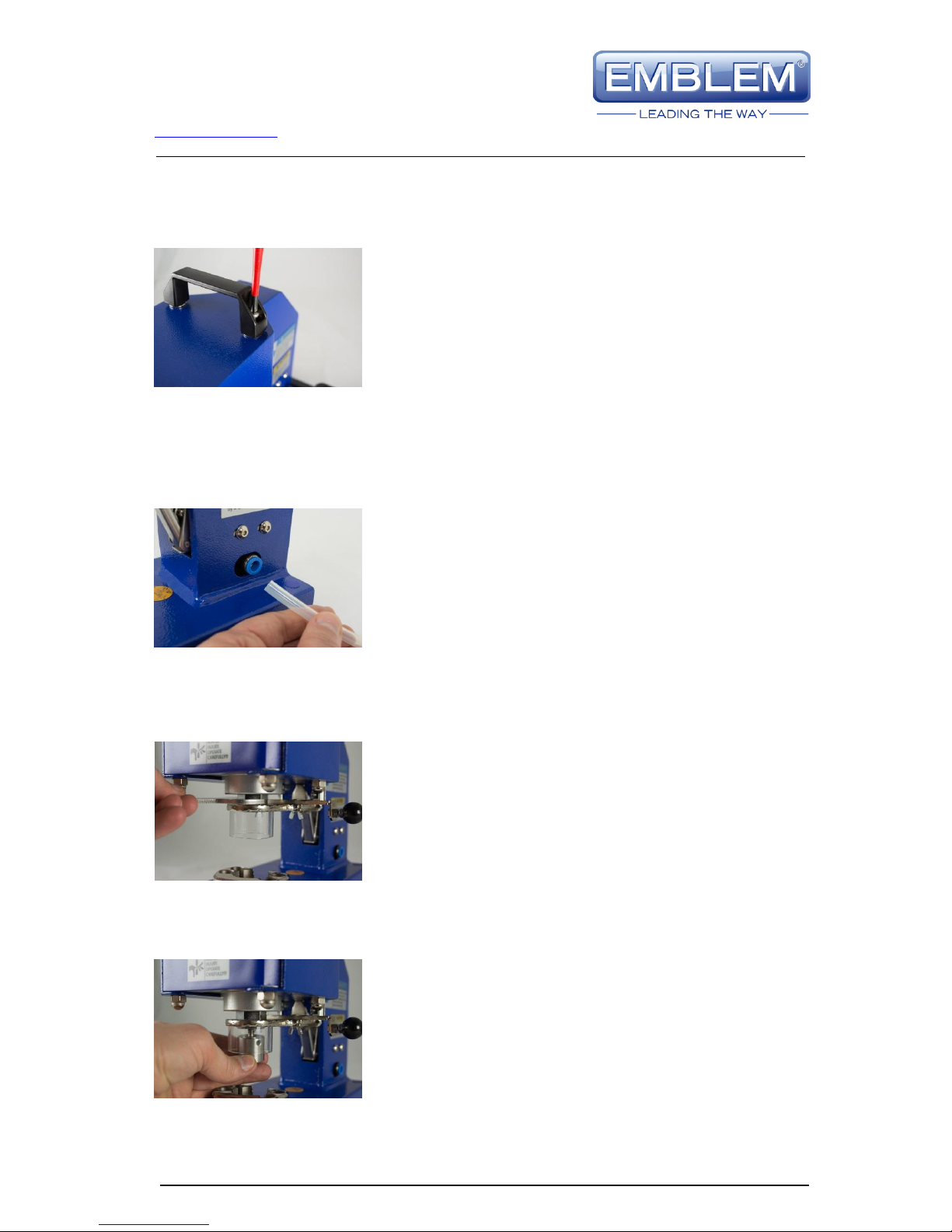
3.2 Installation of the handle
Screw the handle onto the upper side of the device.
3.3 Installation of the die for metal eyelets
1. Remove the compressed air hose.
For the remainder of the installation procedure there
must be no pressure on the device!
!
2. Make certain that the adapter nut is firmly tightened,
using the open-end spanner supplied.
3. Turn the upper die as far as possible into the adapter
nut.

DATAPLOT GmbH
Gutenbergstraße 15
24558 Henstedt-Ulzburg
Germany
Telephone: +49 4193 995-0 Fax: +49 4193 995-220
support@dataplot.de www.dataplot.de
Page 9 / 28
4. Actuate the manual operating lever to drive the finger
guard downwards.
Turn the upper die all the way into the adapter nut and
tighten with the fingers.
5. Loosen the right screw for the lower die with a
screwdriver.
6. Turn out the screw until it is no longer visible in the
hole.
7. Insert the lower die into the hole and press up to the
stop.
8. Tighten the screw for the lower die and then check the
adjustment as described in Section 5.1.
Faulty adjustment causes poor results and can damage
the die.

DATAPLOT GmbH
Gutenbergstraße 15
24558 Henstedt-Ulzburg
Germany
Telephone: +49 4193 995-0 Fax: +49 4193 995-220
support@dataplot.de www.dataplot.de
Page 10 / 28
3.4 Installation of the die for plastic eyelets
1. Remove the compressed air hose.
For the remainder of the installation procedure there
must be no pressure on the device!
2. Remove the adapter nut using the open-end spanner.
The adapter nut is not required for this die. Save the
adapter nut for later use with a die for metal eyelets.
3. Actuate the manual operating lever to drive the finger
guard downwards.
Slide the upper die over the finger guard and turn the
die into the upper mount.
4. Tighten the upper die using the open-end spanner
supplied.
5. Loosen the right screw for the lower die with a
screwdriver.

DATAPLOT GmbH
Gutenbergstraße 15
24558 Henstedt-Ulzburg
Germany
Telephone: +49 4193 995-0 Fax: +49 4193 995-220
support@dataplot.de www.dataplot.de
Page 11 / 28
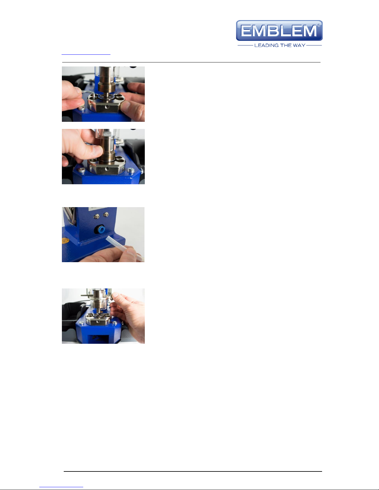
6. Turn out the screw until it is no longer visible in the
hole.
7. Insert the lower die into the hole and press up to the
stop.
8. Tighten the screw for the lower die.
9. Loosen the two front screws on the lower bracket.
10. Pull the upper die downwards with the fingers and
move the lower bracket so that the upper die fits into
the hole of the lower die without snagging.
DATAPLOT GmbH
Gutenbergstraße 15
24558 Henstedt-Ulzburg
Germany
Telephone: +49 4193 995-0 Fax: +49 4193 995-220
support@dataplot.de www.dataplot.de
Page 12 / 28
11. Tighten the two front screws on the lower bracket.
12. Slide the upper die several times completely into the
lower die and control that the upper die is centred in
the lower die without snagging.
13. Connect the compressed air hose.
14. Drive the finger guard with the manual operation lever
slowly downwards and control that the upper die is
centred in the lower die without snagging. If this is not
the case, adjust the die as described in Section 5.1.
Faulty adjustment causes poor results and can damage the die. Such damage is not under
warranty!
DATAPLOT GmbH
Gutenbergstraße 15
24558 Henstedt-Ulzburg
Germany
Telephone: +49 4193 995-0 Fax: +49 4193 995-220
support@dataplot.de www.dataplot.de
Page 13 / 28
3.5 Compressed air connection
The device has a quick coupling connection on the right side. Attach the open 8mm
compressed air hose to the coupling, which automatically holds the hose. To remove the
hose, press the snap ring on the connection and simultaneously pull out the hose.
The outlet pressure of the compressor must be regulated so that a maximum pressure of 7
bars (101 psi) in the device is never exceeded. A pressure higher than 7 bars can damage
the device and cause serious injuries to the operator.
The device operates with a pressure of 5-7 bars. It is designed to give the best results for
an air pressure of 6 bars. Permanent operation with a pressure above 6 bars increases
wear.
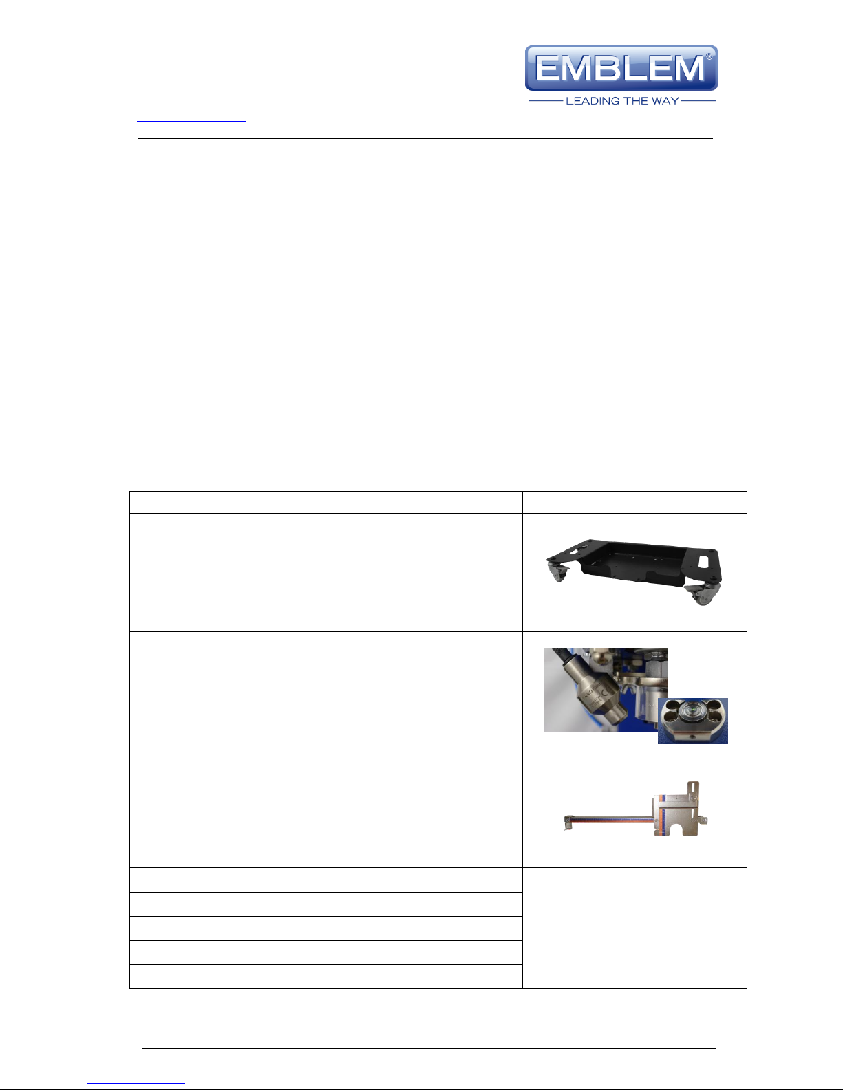
3.6 Optional accessories
The following optional accessories are available:
Art. no.
Description
Illustration
25044
Trolley
including two holders for the grommets and washers
and angular adapter for compressed air connection
25045
LED pointer
I
including power supply and battery compartment
20918
Spacer
25102
Eyelet mount for 8mm metal eyelets
Not pictured
25103
Eyelet mount for 9.5mm metal eyelets
25042
Eyelet mount for 11mm metal eyelets
25104
Eyelet mount for 18.2mm metal eyelets
25043
Eyelet mount for 12mm plastic eyelets

DATAPLOT GmbH
Gutenbergstraße 15
24558 Henstedt-Ulzburg
Germany
Telephone: +49 4193 995-0 Fax: +49 4193 995-220
support@dataplot.de www.dataplot.de
Page 14 / 28
3.7 Installation of the optional trolley
1. Remove the four blue stickers over the drill holes.
2. Remove the four plastic feet on the lower side.
3. Screw the device onto the trolley.
LED pointer
Trolley

DATAPLOT GmbH
Gutenbergstraße 15
24558 Henstedt-Ulzburg
Germany
Telephone: +49 4193 995-0 Fax: +49 4193 995-220
support@dataplot.de www.dataplot.de
Page 15 / 28
4. Cut away a piece (approx. 25mm long) of the
compressed air hose (not supplied) and attach it to the
angular piece supplied.
5. Attach the other end of the 25mm long hose to the
connection on the device.
3.8 Installation of the optional LED pointer
1. Prepare the LED pointer as shown in the photo at the
left. You may have to screw this onto the bracket.
2. Remove the nut from the rear left screw.
3. Attach the Laser pointer on the screw, but don't yet
tighten the nut.

DATAPLOT GmbH
Gutenbergstraße 15
24558 Henstedt-Ulzburg
Germany
Telephone: +49 4193 995-0 Fax: +49 4193 995-220
support@dataplot.de www.dataplot.de
Page 16 / 28
4. Lay a punched banner section in the centre of the die.
For multi-layer punching lay several accordingly over
each other. Then adjust the laser point so that it points
to the centre of the punched section.
5. To adjust towards the front and rear rotate the bracket
in the horizontal plane.
6. To adjust towards the left and right rotate the pointer.
The Phillips-head screw is the fulcrum and under the
wing screw is an elongated hole for adjusting the
position.
7. Actuate the manual operating lever downwards to check
that the upper die cannot collide with the LED pointer.
8. Connect the power supply to the pointer or glue the
battery compartment to a suitable spot und connect.

DATAPLOT GmbH
Gutenbergstraße 15
24558 Henstedt-Ulzburg
Germany
Telephone: +49 4193 995-0 Fax: +49 4193 995-220
support@dataplot.de www.dataplot.de
Page 17 / 28
3.9 Replacing the batteries of the LED pointer
1. To replace the batteries in the battery compartment
remove the locking screw.
2. Then insert a flat screwdriver into the mount and
carefully rotate.
3. The cover should then lift on this side.
4. Pull the cover in the direction of the arrow A and
carefully turn it upwards. Take care that the nib B does
not break off.
5. Replace the two batteries with the battery type AA-Mignon.
Ensure the correct polarity.
Then proceed in the opposite sequence to close the battery compartment again.
B
A

DATAPLOT GmbH
Gutenbergstraße 15
24558 Henstedt-Ulzburg
Germany
Telephone: +49 4193 995-0 Fax: +49 4193 995-220
support@dataplot.de www.dataplot.de
Page 18 / 28
3.10 Installation of the optional spacer
1. Remove the yellow sticker and the upper and lower
dies.
2. Remove the left screw.
3. Position the spacer so that pins A, B and C fit into the
corresponding holes A, B and C. Press the spacer all the
way down.
4. Fix the spacer with the left screw.
A
B
C
A
B
C

DATAPLOT GmbH
Gutenbergstraße 15
24558 Henstedt-Ulzburg
Germany
Telephone: +49 4193 995-0 Fax: +49 4193 995-220
support@dataplot.de www.dataplot.de
Page 19 / 28
4Changing the dies
4.1 Metal eyelets > metal eyelets
1. Remove the compressed air hose.
For the remainder of the installation procedure there
must be no pressure on the device!
2. Actuate the manual operating lever to drive the finger
guard downwards.
Loosen the upper die with the open-end spanner and
turn out as far as possible.
3. Actuate the manual operating lever to drive the finger
guard upwards and turn out the die completely.
4. Loosen the right screw for the lower die with a
screwdriver.

DATAPLOT GmbH
Gutenbergstraße 15
24558 Henstedt-Ulzburg
Germany
Telephone: +49 4193 995-0 Fax: +49 4193 995-220
support@dataplot.de www.dataplot.de
Page 20 / 28
5. Remove the punch waste collecting container. Press the
lower die upwards with the finger and remove the die.
Continue as described from Step 2 in Section 3.3.
4.2 Plastic eyelets > plastic eyelets
1. Remove the compressed air hose.
For the remainder of the installation procedure there
must be no pressure on the device!
2. Actuate the manual operating lever to drive the finger
guard downwards.
Loosen the upper die with the open-end spanner
supplied and turn it out completely.
3. Loosen the right screw for the lower die with a
screwdriver.
Table of contents


