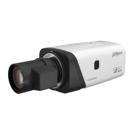
EMBRON HATTELAND TECHNOLOGY SeaHawk HT FBVF A-X1... User manual

Please visit www.hattelandtechnology.com for the latest electronic version of this manual.
USER MANUAL
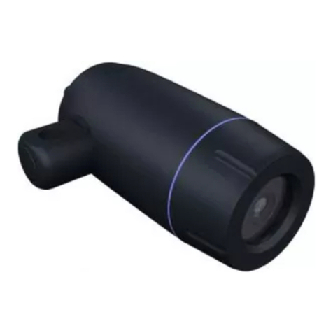
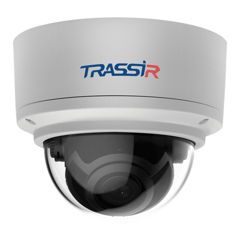
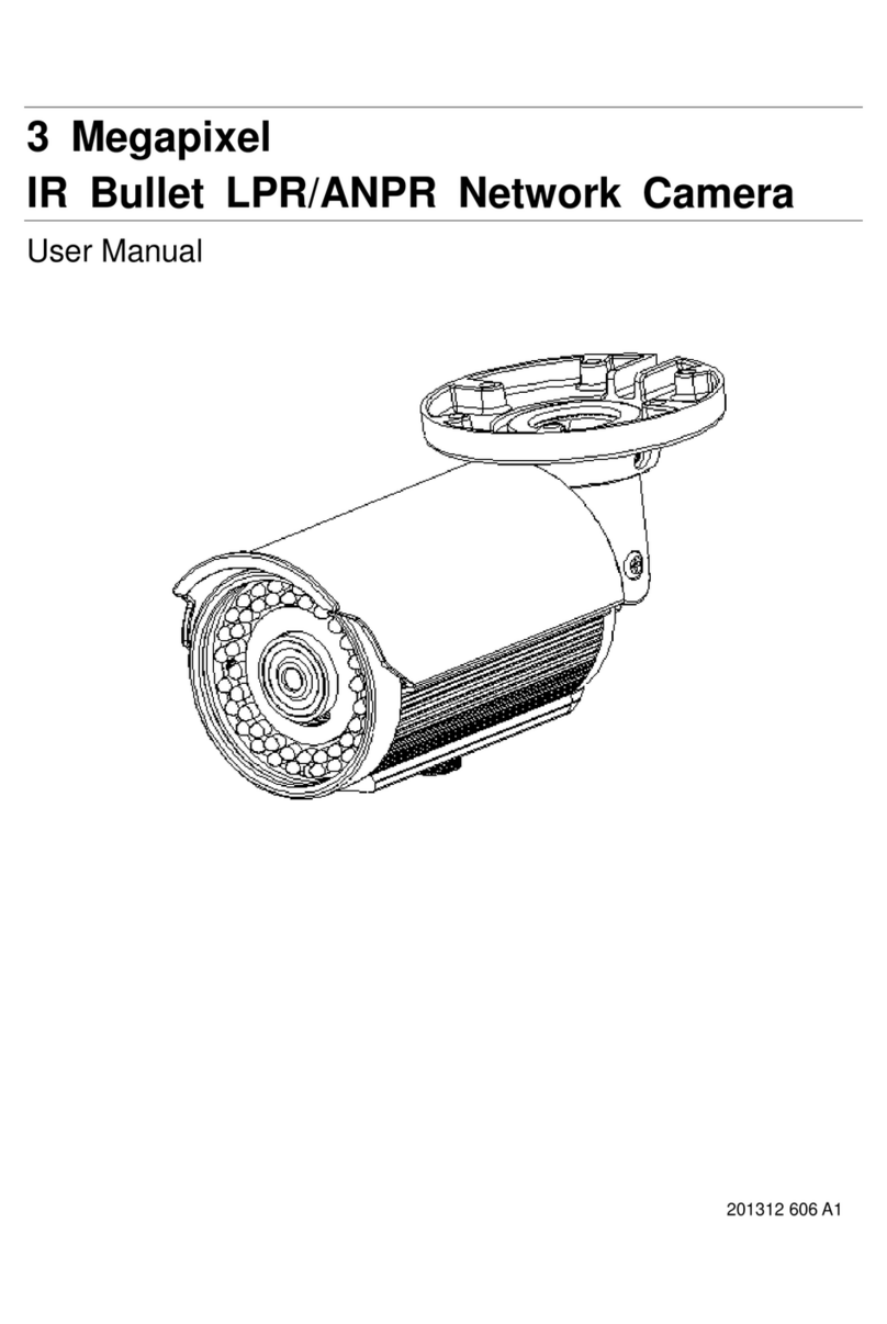
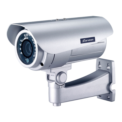
HT FBVF yA-X1 (SeaHawk FixedBullet Varifocal)
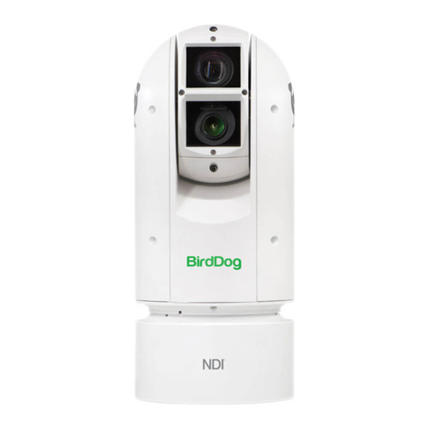
HT ZB2X yA-X1 (SeaHawk ZoomBullet 20x)
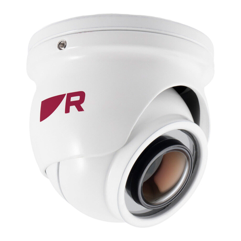
HT FDFL yA-X3 (SeaHawk FixedDome Fixed Lense
where “Y” is housing Material
HATTELAND®SeaHawk IP Camera
User Manual SeaHawk IP Camera
Updated: 04 Feb 2021 Doc Id: INB101611-1 (Rev 01)
Created: 8370 Approved: 8370

Copyright © 2020 Hatteland Technology AS
Eikeskogvegen 52, N-5570 Aksdal, Norway.
All rights are reserved by Hatteland Technology AS. This information may not, in whole or in part, be
copied, photocopied, reproduced, translated or reduced to any electronic medium or machine-
readable form without the prior written consent of Hatteland Technology AS. Review also:
www.hattelandtechnology.com/hubfs/pdf/misc/doc100703-1_permission_to_create_user_manuals.pdf
The products described, or referenced, herein are copyrighted to the respective owners.
The products may not be copied or duplicated in any way. This documentation contains proprietary
information that is not to be disclosed to persons outside the user’s company without prior written consent
of Hatteland Technology AS.
The copyright notice appearing above is included to provide statutory protection in the event of
unauthorized or unintentional public disclosure.
All other product names or trademarks are properties of their respective owners !
WARNING: This is a class A product. In a domestic environment this product may cause radio interference
in which case the user may be required to take adequate measures.
Statement above last revised 31 Jul. 2019

3
IND100206-31
Contents
Contents.................................................................................... 3
General ...................................................................................... 5
About Hatteland Technology .......................................................................5
www.hattelandtechnology.com ....................................................................5
Contact Information .....................................................................................5
1. Introduction........................................................................... 7
1.1 About this manual..................................................................................7
1.2 Features ................................................................................................7
1.3 Product and Accessories.......................................................................8
1.4 Contents of package .............................................................................9
1.5 System Connections ...........................................................................10
2. Installation........................................................................... 12
2.1 Connecting Network ............................................................................12
3. System Operation............................................................... 14
3.1 Remote Video Monitoring....................................................................14
3.2 Live View Overview .............................................................................15
4. Remote Conguration........................................................ 17
4.1 Using Web Browser.............................................................................17
4.2 Video & Audio ......................................................................................18
4.3 Image ..................................................................................................22
4.4 Network ...............................................................................................29
4.5 Event ...................................................................................................43
4.6 Record.................................................................................................49
4.7 User.....................................................................................................51
4.8 System ................................................................................................54

Contents
4
IND100206-31
5. Technical Drawings ............................................................ 61
5.1 Technical Drawing: HT FBVF xx-X1 / HT ZB2X xx-X1 ..........................................62
5.2 Technical Drawing HT FDFL-xx-X3 .......................................................................63
5.3 Technical Drawing HT CB1x-AA ............................................................................64
5.4 Technical Drawing HT WB1x-AA ...........................................................................65
5.6 Technical Drawing HT MB1x-AA............................................................................66
5.7 Technical Drawing LD-001.....................................................................................69
Appendixes ............................................................................. 70
Return Of Goods Information ....................................................................70
General Terms and Conditions..................................................................71
Revision History ........................................................................................72

5
Hatteland Technology AS
IND100077-1
General
About this manual
The manual contains electrical, mechanical and input/output signal specications. All specications in this manual,
due to manufacturing, new revisions and approvals, are subject to change without notice. However, the last updated
and revision date of this manual are shown both on the frontpage and also in the “Revision History” chapter. This
user manual is a standard/general manual that applies to all variations of its product family, i.e. deviation from actual
conguration may exist.
About Hatteland Technology
Hatteland Technology is the leading technology provider of specialized display and computer products, delivering high
quality, unique and customized solutions to the international maritime, naval and industrial markets.
The company represents innovation and quality to the system integrators worldwide. Effective quality assurance and
investment in sophisticated in-house manufacturing methods and facilities enable us to deliver Type Approved and Mil
tested products. Our customer-oriented approach, technical knowledge and dedication to R&D, makes us a trusted
and preferred supplier of approved solutions, which are backed up by a strong service network.
www.hattelandtechnology.com
You will nd our website full of useful information to help you make an informed choice as to the right product for your
needs. You will nd detailed product descriptions and specications for the entire range on Displays, Computers and
Panel Computers, Military solutions as well as the range of supporting accessories. The site carries a wealth of
information regarding our product testing and approvals in addition to company contact information for our various
oces around the world, the global service locations and the technical help desk, all ensuring the best possible
support wherever you, or your vessel, may be in the world.
Contact Information
Head oce, Aksdal / Norway:
Hatteland Technology AS
Eikeskogvegen 52
N-5570 Aksdal, Norway
Switchboard:
Tel: +47 4814 2200
mail@hattelandtechnology.com
Sales oce, Frankfurt / Germany:
Hatteland Technology GmbH
Werner Heisenberg Strasse 12,
D-63263 Neu-Isenburg, Germany
Uwe Scheumann:
Tel: +45 2463 9565
Elke Freisens:
Tel: +49 173 6174753
Sales oce, Oslo / Norway:
Hatteland Technology AS
Strandveien 35
N-1366 Lysaker
Norway
Switchboard:
Tel: +47 4814 2200
mail@hattelandtechnology.com
Sales oce, Aix-en-Provence / France:
Hatteland Technology SAS
Actimart- 1140, rue Ampère, CS 80544
13594 Aix-en-Provence, Cedex 3
France
Mehdi Bounoua (Sales Director Europe, Middle East & Africa):
Tel : +33 6 88 33 64 93
Sales oce, Vista / USA:
Hatteland Technology Inc
450 South Melrose Drive,
Suite #107
Vista, CA 92081
USA
Donna Pallonetti:
Tel: +1 858-282-0659
Fax: +1 858-408-1834
For an up-2-date list, please visit https://www.hattelandtechnology.com/contact

6
This page left intentionally blank

7
IND101057-27
3 Feb. 2021 Hatteland Technology AS | www.hattelandtechnology.com | Enterprise no: NO974533146 Page 7 of 66
1. Introduction
1.1 About this manual
This User Manual provides information on operating and managing the Seahawk IP camera.
The Manual includes instructions of installation, operation and configuration of Seahawk IP
camera as well as how to troubleshoot.
1.2 Features
Video
⚫Highly efficient compression algorithm, H.264, H.265 & MJPEG support
⚫1920x1080@30FPS
⚫Wide range of encoding and decoding options : CIF(352c240) ~ FULL HD (1920x1080)
⚫Wide range of transmission rates: 32kbps ~ 16mbps
⚫Various transmission modes: CBR, VBR, Hybrid
⚫Motion detection
⚫Quad Streaming
Network
⚫Fixed IP & Dynamic IP (DHCP) support
⚫1:1, 1:N support
⚫Multicasting
⚫Various types of Protocol support: TCP/IP, UDP, Multicast, DHCP, SMTP, HTTP, SNMP,
RTP, RTSP
⚫OnVIF, PSIA compliant
Sensor and Alarm
⚫Support direct connections of external sensor and alarm devices
⚫Event Alarm notification.
⚫If an external sensor is activated, camera can be set to move to the corresponding Preset
position.
User Interface
⚫Diagnose and upgrade through dedicated program called True Manager
⚫System configuration using Internet Explorer
High Reliability
⚫Reliable embedded system

8
IND101057-27
3 Feb. 2021 Hatteland Technology AS | www.hattelandtechnology.com | Enterprise no: NO974533146 Page 8 of 66
1.3 Product and Accessories
HT FBVF xx-X1 HT FDFL xx-X3 HT ZB2X xx-X1
LD-001 HT CB1x-AA HT WB1x-AA HT MB1x-AA

9
IND101057-27
3 Feb. 2021 Hatteland Technology AS | www.hattelandtechnology.com | Enterprise no: NO974533146 Page 9 of 66
1.4 Contents of package
Item Description Illustration
LD-001
RJ45 Waterproof Coupler shielded
HT MB1x-AA
SeaHawk Bullet Ceiling/Wall Bracket (not included with HT FDFL YA-X3)
includes:
1 x PO25745 - Bullet Camera Bracket Black RAL9005
or
1 x SeaHawk Bullet Ceiling/Wall Bracket White RAL9010
1 x Quick Start Guide
Note: Entries listed below are for Standard factory shipments. Customized factory shipments may deviate from this list.
ø30
30.00 [1.18]
134.50 [5.29]
ø30
30.00 [1.18]
134.50 [5.29]
90.00
3.54
131.00
5.16
30.00
1.18
60.00
2.36
3 x
10.50
0.41
THRU
50.00
1.97
199.00
7.83
32.00
1.26
3
ItemNo
Quantity
Description
ID.
Revision
Material
1 1
Bullet Camera Bracket Black
P025745
02
AISI Type 316L stainless steel
2 1
Bullet Camera Bolt M20 Black
P025743
03
AISI Type 316L stainless steel
3 2
DIN 7991 - M5 x 14
01
4 1
DIN 985 - M20x1.5
01
5 1
Washer M20
01
Plastic
6 1
Plastic Cap Ø28.55mm (Black)
01
Plastic
7 1
3mm allen/hex key
01
1
2
4
5
131.00
5.16
109.50
4.31
5.00 0.20
90.00
3.54
32.00
1.26
1
2
4
3
5
50.00
1.97
30.00
1.18
60.00
2.36
3 x
10.50
0.41
THRU
Wall Mount Setup
Ceiling Mount Setup
Sales Drawing
HT MB11-AA (SeaHawk Bullet Ceiling/Wall Bracket Black)
Stainless steel (A4)
(Black)
Units: mm [inches]
Stainless steel
(Black)
F
1
E
D
2
3
4
C
B
A
1
2
3
4
5
6
7
8
F
E
D
C
B
A
5
6
Hatteland Technology AS
Eikeskogvegen 52
N-5570 Aksdal
A012065
Projection
Revision:
This document is the property of Hatteland Technology AS.
This document and any authorized reproduction thereof, must not be used in
any way against the interest of Hatteland Technology AS.
Any authorized reproduction, in whole or in part, must include this legend.
Approved by:
01
Drawing number:
A2
1:2
Colour code:
Scale:
Surface treatment:
Sheet
/
1 3
7
8
Tolerance
Welding
specification
NS-EN-288-4
ISO 2768-mK
Last rev. date / by: /
Creation date / by: /
8744
21.10.19
For dimensions not shown, see DWG or 3D model.

10
IND101057-27
3 Feb. 2021 Hatteland Technology AS | www.hattelandtechnology.com | Enterprise no: NO974533146 Page 10 of 66
or
or
or
1.5 System Connections
The Seahawk IP Cameras can be connected in either 1 to 1 connection where one SeaHawk
Camera is connected to one PC client or a decoder system or 1 to many connections where one
TN-B220xT.can be connected to several PCs and decoder systems. (TCS-2000 video server can
work as a video decoder which takes the data from a video server or IP camera, decodes and
outputs analog video.)
Topology
Generally, a Seahawk Camera and PC or a decoder is connected in 1-to-1 mode or 1-to many
configuration.
1:1 Connection
One Seahawk camera is installed at a site where video images are transmitted. A PC or a
decoder is installed at a central location to receive and view the video images on an analog
monitor. Audio and serial data are transferred in either direction.
1:N Connection
In this configuration, a site can be monitored from many remote central locations. Although up to
64 PCs or decoders can be connected to one SeaHawk IP Camera in the real network
environment, network bandwidth can limit the maximum connections. Functionally of the video
Management system (VMS) software provided can replace the decoder.
Site
Remote Center (Decoder) Remote Center
Site
Remote Center (PC SW)
Site
Remote Center

11
IND101057-27
3 Feb. 2021 Hatteland Technology AS | www.hattelandtechnology.com | Enterprise no: NO974533146 Page 11 of 66
Multicast Mode
If the network supports multicasting, a large number of decoders can be used to receive video
effectively from a SeaHawk IP Camera using a single streaming of video and audio. However,
multicast mode is possible only when network environment supports multicast.
Relay
Video and audio data can be retransmitted from a center to another center. The arrangement is
useful when the network bandwidth to the site is limited when there are more than one center,
that want to monitor the site.
VMS (Video Management System)
VMS (Video Management System) is a Window-based remote monitoring program in order to
monitor or control video, audio, and events in real time from several IP cameras or video servers.
Please refer to the VMS User Manual for more in detail.
Site
Remote Center
Site
Center 1(Decoder) Center 2 (Decoder)
Site
Remote Center (Decoder) VMS
3 Feb. 2021 Hatteland Technology AS | www.hattelandtechnology.com | Enterprise no: NO974533146 Page 10 of 66
or
or
or
1.5 System Connections
The Seahawk IP Cameras can be connected in either 1 to 1 connection where one SeaHawk
Camera is connected to one PC client or a decoder system or 1 to many connections where one
TN-B220xT.can be connected to several PCs and decoder systems. (TCS-2000 video server can
work as a video decoder which takes the data from a video server or IP camera, decodes and
outputs analog video.)
Topology
Generally, a Seahawk Camera and PC or a decoder is connected in 1-to-1 mode or 1-to many
configuration.
1:1 Connection
One Seahawk camera is installed at a site where video images are transmitted. A PC or a
decoder is installed at a central location to receive and view the video images on an analog
monitor. Audio and serial data are transferred in either direction.
1:N Connection
In this configuration, a site can be monitored from many remote central locations. Although up to
64 PCs or decoders can be connected to one SeaHawk IP Camera in the real network
environment, network bandwidth can limit the maximum connections. Functionally of the video
Management system (VMS) software provided can replace the decoder.
Site
Remote Center (Decoder)
Remote Center
Site
Remote Center (PC SW)
Site
Remote Center

12
IND101057-27
3 Feb. 2021 Hatteland Technology AS | www.hattelandtechnology.com | Enterprise no: NO974533146 Page 12 of 66
2. Installation
2.1 Connecting Network
ͳǤ Plug network cable to Power over Ethernet port (RJ-45 network port).
Once the power is supplied to the camera, it will start booting. The system will boot up to an
operating mode after approximately 40-60 seconds. The green LED on the Ethernet port will flash
indicating the system is ready.
ʹǤ Connect a Computer to the Seahawk IP Camera with an ethernet cable to a RJ-45 network port.
͵Ǥ Setup the network of the computer in the same IP range as the camera.
(Seahawk Default IP:192.168.1.90, Subnet mask: 255.255.255.0)
a. Right click on the network icon (in the right bottom corner), then left click “open Network &
Internet settings”.
b. Left click “Ethernet” on left side of settings window, then left click Change adapter options.

13
IND101057-27
3 Feb. 2021 Hatteland Technology AS | www.hattelandtechnology.com | Enterprise no: NO974533146 Page 13 of 66
c. Right click on the Ethernet Port Connected to the Switch/Camera and left click “Properties”.
d. Double click on “Internet Protocol Version 4 (TCP/IPv4), Check the box with “Use the Following
IP address”. Now enter an IP address and Subnet mask into the fields. The IP address needs
to be in the range of the cameras IP address: 192.168.1. 3 – 192.168.1.245 (except for IP
addresses being used, such as camera IP 192.168.1.90). Example:
IP address: 192.168.1.244
Subnet mask: 255.255.255.0
Default gateway: ___.___.___.___
e. Click “OK” on both widows to confirm the changes.

14
IND101057-27
3 Feb. 2021 Hatteland Technology AS | www.hattelandtechnology.com | Enterprise no: NO974533146 Page 14 of 66
3. System Operation
3.1 Remote Video Monitoring
- There are two ways to monitor video when the center system and IP camera are connected.
In order for a proper operation, an IP address must be set accordingly. Default password is
requested modification for better security.
Default ID : admin
Default Password : admin
Video Monitoring using Firefox
- Open Firefox and enter camera’s IP address. The system will ask for confirmation
to install Active-X control. Once authorized, the browser will start to display video
images from camera as shown below.
➢Default IP Address : http://192.168.1.90
Video Monitoring using Google Chrome
- Open Google Chrome and enter camera’s IP address. The system will ask for confirmation to
install Active-X control and also enable Native client in the browser.
To enable Native client follow the steps below:
1. Open the chrome browser
2. Type the following into the URL search bar: chrome://flags/
3. In the “Search flags” search bar Type: native client
4. Click enabled.
5. Restart the browser.
Figure 1 Live View for the Hatteland Seahawk

15
IND101057-27
3 Feb. 2021 Hatteland Technology AS | www.hattelandtechnology.com | Enterprise no: NO974533146 Page 15 of 66
Video Monitoring using RTSP
Default:
Primary stream: rtsp://192.168.1.90:554/video1
Secondary#1: rtsp://192.168.1.90:554/video2
Secondary#2: rtsp://192.168.1.90:554/video3
Custom address:
3.2 Live View Overview
◆Video Select
- Select the Video stream to be viewed: Primary, Secondary #1,
#2, #3.
- This video server is capable of quadruple streaming; primary
streaming and secondary streaming #1~#3.
- Video will be displayed according to the resolution set on video
configuration. If dual or quadruple streaming (“Use Dual
Encode” Menu in Video page) is not activated, secondary video
is not available
◆View Size
- Adjust the size of the screen on the browser. Screen size is
initially adjusted according to the resolution of video page
◆Digital Zoom
- Control the Digital zoom on the screen. The more the camera
zooms in, the smaller the square of control panel is. Position of
the image can be changed by moving position of the square. If
you press x1, the screen will return to the normal size.
◆Zoom Control
- Control PTZ and PTZ Control Panel is used for controlling
external PTZ devices when the external PTZ device is
connected through serial port. It is possible to make zooming
control by Zoom in/out buttons of PTZ control Panel (In order
to use digital zoom, select Digital zoom ON in the Camera tab)
- Stop
Stop on-going action
- Focus Near, Focus Far, Auto Focus
Adjust the focus of the lens

16
IND101057-27
3 Feb. 2021 Hatteland Technology AS | www.hattelandtechnology.com | Enterprise no: NO974533146 Page 16 of 66
◆Select Preset
- Set preset position and move to the specific preset position if
PTZ Camera is connected to Video Server via Serial Port Set
- Goto:
Move to the selected preset entry if the preset entry is set.
- Set:
Set the current position to the selected preset entry.
- Clear:
Delete the selected preset entry.
◆Sensor Input and Alarm Output
- Display the status of the sensor in real time. When the sensor
of the video server is working, the sensor light turns red and
operate the alarm
device by pressing the number icon. A
number icon indicates status of the alarm device.
◆Snapshot
- Capture video images and store them as BMP or JPEG files.
◆Talk
- Transfer audio from PC’s mic to the camera
◆File Record
- Recording to an AVI file on Live View page is available. AVI
files are generated in the specified folder or in a specified file
name on the PC where web browser is running.
1. Press “Set” button to select a folder or create a new folder.
Enter the file name on a filename field.
2. Press “Start” button to start recording.
3. Press “Stop” button to stop recording.
4. An AVI file named “IP address_hh_mm_ss” or “File
name_IP address_hh_mm_ss” will be generated in the
specified folder depending on where the path specified
folder or a prefix of the file
name.
Video Monitoring with Decoder System
Once camera’s IP address is set in the remote IP address section of the decoder, the
decoder system will connect to camera and start receiving the video images. Normally, a
monitor connected to the decoder will display video images

17
IND101057-27
3 Feb. 2021 Hatteland Technology AS | www.hattelandtechnology.com | Enterprise no: NO974533146 Page 17 of 66
4. Remote Configuration
4.1 Using Web Browser
Remote setting is available by using web browser. Enter IP address of camera and then a
live view screen appears as below. Press Setup button located in the upper right area of the
monitoring screen to go to the server setup. For Remote Setting, user should be authorized
higher than manager level.
The configurations are grouped into 9 categories: Video & Audio, Image, Network, Event,
Record, Device, PTZ, System, User. Leaving the page without pressing Apply button, any
changes in the page will be discarded.
Enter IP Address
Figure 2 Live View in Browser
Press Setup button

18
IND101057-27
3 Feb. 2021 Hatteland Technology AS | www.hattelandtechnology.com | Enterprise no: NO974533146 Page 18 of 66
4.2 Video & Audio
Information
Figure 3 Setup, Video & Audio, Information
-The information provides current information regarding the settings for video and
Audio
Click to return to Live View

19
IND101057-27
3 Feb. 2021 Hatteland Technology AS | www.hattelandtechnology.com | Enterprise no: NO974533146 Page 19 of 66
Video
Figure 4 Setup, Video & Audio, Video, Primary
- Performance Calculation
Shows the performance usage rate according to the value set at ‘Encode’ mode
underneath.
- Input Format
User can select input format
- Algorithm
Select compression algorithm and MJPEG is supported for only Secondary streams.
- Resolution
Select video encoding solution.
Scaling option is used when encoding resolution is different from input resolution.
Without Scaling option, input video will be cut according to encoding resolution. On the
other hand, if Scaling is selected, input video will be adjusted according to encoding
resolution.
- Framerate
Determine the maximum number of frames per second for the video stream.

20
IND101057-27
3 Feb. 2021 Hatteland Technology AS | www.hattelandtechnology.com | Enterprise no: NO974533146 Page 20 of 66
1,2,3,4,5,6,8,10,15,20,25, 30 and 60 frame rate can be selected. The actual frame rate of
video can be less than the maximum frame rate set due to the network bandwidth
limitation
- Preference
Select encoding mode to control video quality or bitrate: Quality(VBR) or Bit rate(CBR
and Hybrid). If ‘Bitrate’ selected, the video encoding will be effected by the ‘Bitrate’ value
entered. Therefore, “Bitrate” mode corresponds to CBR (Constant Bit Rate) or Hybrid
(Hybrid Constant Bit Rate) encoding. If ‘Quality’ selected, the video encoding will be
effected by the quality of image selected. Therefore, “Quality” mode corresponds to VBR
(Variable Bit Rate) encoding
- Quality
Select Video quality. 8 levels of quality are available.
Quality mode (VBR encoding) tries to encode every frame in a constant quality.
Therefore, resulting bitrate may vary a lot depending on the complexity or activity
changes in the input video. It is preferred when constant video quality is required and
network bandwidth is enough for delivering the stream of highly varying bitrate.
- Bitrate
Determine bitrate value between 32 ~ 16Mbps.
Bitrate mode (CBR encoding) allows you to set a fixed target bitrate that consumes a
predictable amount of bandwidth. In order to keep the bitrate limit, video quality is
controlled dynamically according to the complexity or activity changes in the input video.
Bitrate mode (Hybrid encoding) allows you to set a maximum bitrate. Bitrate does not
exceed the set bitrate but it can be decreased automatically when the scene complexity
is decreased. This mode allows you to control the bandwidth efficiently.
- I-Frame Interval
Determine I-frame Interval between 1 and 255.
- ROI (Region of Interest) Enable
Select ON to encode only preferable part of the scene. Drag a mouse on the image in
order to set a area that you prefer to encode. This mode allows you to save over 30% of
bitrate and result in saving cost of storage more than 30%.
This manual suits for next models
2
Table of contents
Other EMBRON Security Camera manuals
