EMC Services Zero Wire User manual

EMC Services -Consulting engineers in EMC, EMR, RF hazards and site surveys
International - Tel 61-2-9975 4555, Fax 61-2-9876 2796, E-Mail in[email protected]u
EMC Services Pty Ltd
ABN 42 072 235 306
12/8 Tilley Lane
Frenchs Forest NSW 2086
Australia
Tel: +61 2 9975 4555
Fax: +61 2 9876 2796
Web: www.emc.net.au
Report No. 140805-2a
Compliance Testing Report of the “Zero Wire Alarm System” to
FCC Part 15 (B) Class B (ANSI C63.4:2003) and
FCC part 15 (C) Para 15.249 (ANSI C63.4:2003)
for
UHS Systems Pty Ltd
Prepared by: __________________ Reviewed by: _______________
Michael Matevski Geoff Garrett
Date: 13th November 2014
This report may not be reproduced whole or in part without the permission
of EMC Services Pty Ltd

Report No 140805-2a Page 2of 18
This report may not be reproduced in whole or in part without the permission
of EMC Services Pty Ltd
Contents
1. Client Information ............................................................................................................................. 3
2. Equipment Under Test (EUT)............................................................................................................ 3
2.1 Identification of EUT ................................................................................................................. 3
2.2 Accessory Equipment ............................................................................................................... 3
2.3 Auxiliary Equipment .................................................................................................................. 3
2.4 Operating Conditions of EUT .................................................................................................... 3
3. Test Specifications ........................................................................................................................... 4
3.1 Standard Selected .................................................................................................................... 4
3.2 Changes from the Selected Standard ....................................................................................... 4
3.3 Test Facility .............................................................................................................................. 4
3.4 Test Equipment......................................................................................................................... 5
4. Test Summary .................................................................................................................................. 6
4.1 Emissions (unintentional) FCC Part 15 (B) Class B, (see Figures 1a to 3b) .............................. 6
4.2 Radiated Emissions (intentional) to FCC part 15 (C) Para 15.249............................................. 6
5. Modifications : None ........................................................................................................................ 6
6. Test Results ..................................................................................................................................... 7
6.1 Test Conditions......................................................................................................................... 7
6.2 Conducted Emissions ............................................................................................................... 7
6.3 Radiated Emissions .................................................................................................................. 7
7. Measurement Uncertainty................................................................................................................. 7
8. Test Plots ......................................................................................................................................... 7
9. Test Facility .................................................................................................................................... 12
10. Photographs ............................................................................................................................... 13
11. Appendices................................................................................................................................. 17

Report No 140805-2a Page 3of 18
This report may not be reproduced in whole or in part without the permission
of EMC Services Pty Ltd
1. Client Information
Company: UHS Pty Ltd
Suite 203, 5-13 Rosebery Avenue,
Rosebery, NSW 2018, Australia
Tel: +61 (0) 2 9663 2299
Web: www.uhssystems.com
2. Equipment Under Test (EUT)
2.1 Identification of EUT
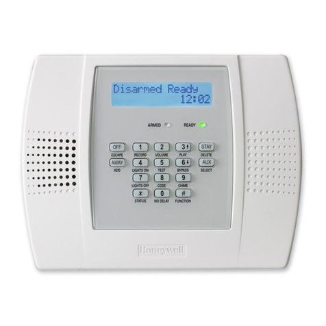
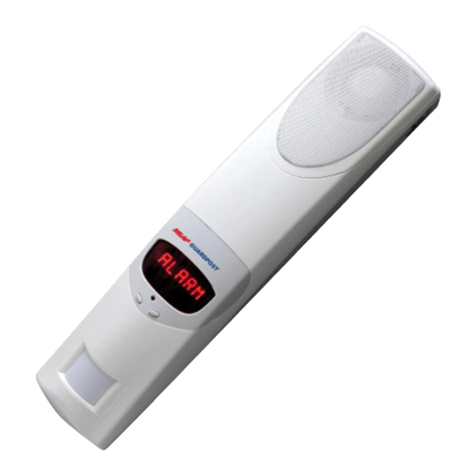
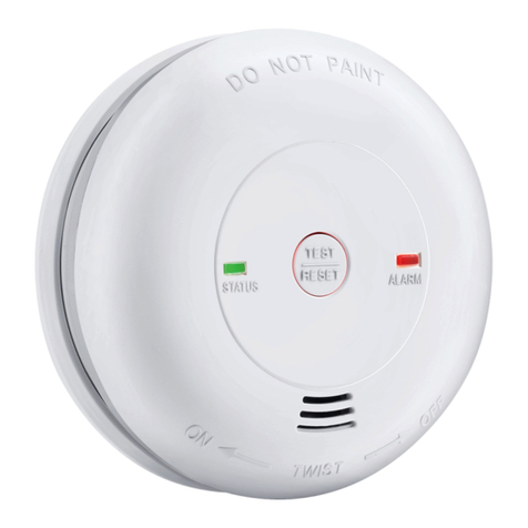
Equipment Description: A security alarm system
Model: Zero Wire
Module Number: ZW-6400H
Make: UHS
Supply: 16 VAC 60 Hz (through an AC Adapter)
2.2 Accessory Equipment
AC Adapter: Make: ZB, Model Number: ZB-A090020A-J
Supply Rating: 120 VAC, 60 Hz
2.3 Auxiliary Equipment
Ethernet Switch: Make - Linksys, Model - SD205
2.4 Operating Conditions of EUT
The tests were performed with the EUT powered by the AC Adapter. The EUT was
orientated manually during the test for maximum emissions. The internal GSM and short
range wireless modules were operational during testing.

Report No 140805-2a Page 4of 18
This report may not be reproduced in whole or in part without the permission
of EMC Services Pty Ltd
3. Test Specifications
3.1 Standard Selected
ANSI C63.4:2003 was selected to demonstrate compliance with the applicable EMC
requirements of FCC Part 15 (B) Class B and FCC Part 15 (C) Para 15.249, as the EUT is
within the scope of this standard, and ANSI C63.4 is the preferred method of compliance
with 47CFR Part 15 rules.
3.2 Changes from the Selected Standard
None
3.3 Test Facility
All EMI tests reported within this document were performed by EMC Services Pty Ltd
measurement facility located at the following location:
Laboratory and Open Area Test Site: Hampton Grove
Rydal Road
Hampton, NSW,
Australia, 2790
10m open area test site (OATS), equipped
with 360 degree remote control turntable and
6 metre remote control antenna mast.
A description of the test facility is on file with the FCC under Registration # 480861 and
with Industry Canada under site number # 2815A-1

Report No 140805-2a Page 5of 18
This report may not be reproduced in whole or in part without the permission
of EMC Services Pty Ltd
3.4 Test Equipment
Test equipment used is from the list below. All equipment was within the current calibration
period and/or confirmed to be within the specified uncertainty.
Description
Model number
Serial number
Calibration due
date
Spectrum analyser
HP 8591EM
3639A00972
5/12/2014
Spectrum analyser
E4407B
US40241411
13/11/2014
Antenna 30 MHz to 2 GHz
CBL6141A
4194
7/6/2015
Double Ridged Horn Antenna, 1 -
18 GHz
BBHA9120
198
9/1/2015
Low noise amplifier
HP8447E
1145A00199
5/12/2014
LISN
LISN15
01
15/6/2015
MCL 20dB 18GHz 5W
attenuator
BW N20W5
Nil
2/5/2015
RF cable
EMCS 01
04
28/4/2015
Cable - Succoflex 104
955604/4
955665/4
10/3/2015

Report No 140805-2a Page 6of 18
This report may not be reproduced in whole or in part without the permission
of EMC Services Pty Ltd
4. Test Summary
4.1 Emissions (unintentional) FCC Part 15 (B) Class B, (see Figures 1a to 3b)
EMC Tests
Result
Note
Conducted Emissions
Pass
-
Radiated Emissions
Pass
-
4.2 Radiated Emissions (intentional) to FCC part 15 (C) Para 15.249
Parameter
Limit
Measured
Result
Frequency :
902 –928 MHz
908.38 MHz
Pass
Field Strength
@ 3 meters:
94 dBμV/m at 3m
87.8 dBμV/m at 3m
Pass
Spurious with
Tx on (30
MHz to 11
GHz)
54 dBμV/m at 3m
47 dBμV/m at 3m
Pass
The results in this report apply only to the tested sample described in Section 2 and depicted
in the photographs attached.
5. Modifications: None

Report No 140805-2a Page 7of 18
This report may not be reproduced in whole or in part without the permission
of EMC Services Pty Ltd
6. Test Results
6.1 Test Conditions
Date of test:
4th September 2014
Temperature:
18oC
Humidity:
51%
Supply Voltage:
120 VAC, 60 Hz
Location:
Hampton Test Site
Test Officer:
M. Matevski
Emissions tests were performed in accordance with the standard referenced in Section 3.
Where the spectrum was occupied by other transmissions (i.e. ambient signals that
approached or exceeded the limit), ‘close-up’ probing and similar investigative procedures
were executed to establish the emission signature of the EUT and whether masked
emissions would approach or exceed the limit at these frequencies. The EUT was
operated to produce maximum emissions at all times.
6.2 Conducted Emissions
The conducted emissions were measured using a LISN on the Active/ Neutral of the mains
terminal. The conducted emission plot and results are shown in figures 1a and 1b. The
minimum margin for Electromagnetic Radiation Disturbance was greater than 9 dB below
the respective limit.
6.3 Radiated Emissions
The radiated peak emission trace results are shown in Figures 2a and 2b. The radiated
testing was performed at an antenna-to-EUT distance of 3 metres. The minimum margin
for Electromagnetic Radiation Emissions was greater than 2.7 dB below the respective
limit. Signals exceeding these levels in the trace results were ambient.
Note: The IF bandwidth of 120 KHz (impulse 6dB) was used for the radiated tests from 30
MHz to 1000 MHz, which corresponds to 100 kHz (power 3dB) shown in figures 2a and 2b.
7. Measurement Uncertainty
The uncertainty of the quantities measured or applied were within the tolerances described
below:
Conducted Emissions + 2 dB
Radiated Emissions + 6 dB
8. Test Plots

Report No 140805-2a Page 8of 18
This report may not be reproduced in whole or in part without the permission
of EMC Services Pty Ltd
Frequency Peak QP Avg
MHz dBuV dBuV dBuV
0.544 49.8 44.7 32.5
0.580 49.3 42.8 31.3
0.703 53.1 47.1 35.8
Figure 1a. Mains Conducted Emissions, 0.15 MHz to 30 MHz
(Active)
Frequency Peak QP Avg
MHz dBuV dBuV dBuV
0.461 52.3 46.4 34.7
0.558 50.2 44.7 32.2
0.629 50.8 45.0 34.1
0.700 53.2 46.3 35.1
Figure 1b. Mains Conducted Emissions, 0.15 MHz to 30 MHz
(Neutral)
Conducted, Quasi-peak
Conducted, Average
-20
-10
0
10
20
30
40
50
60
70
80
1
10
dBuV
(Start = 0.15, Stop = 30.00) MHz
30
0.15
IF Bandwidth 10 kHz
Video bandwidth 30 kHz
Conducted, Quasi-peak
Conducted, Average
-20
-10
0
10
20
30
40
50
60
70
80
1
10
dBuV
(Start = 0.15, Stop = 30.00) MHz
IF Bandwidth 10 kHz
Video bandwidth 30 kHz

Report No 140805-2a Page 9of 18
This report may not be reproduced in whole or in part without the permission
of EMC Services Pty Ltd
Frequency Peak QP
MHz dBuV/m dBuV/m
132.038 45.4 36.6
144.045 47.6 37.0
203.999 49.7 40.5
499.990 44.9 42.5
624.986 46.8 44.3
Note: Signals exceeding the limit level in the plot were ambients.
Figure 2a. Radiated Emissions, 30 MHz to 1000 MHz
(Horizontal)
FCC Part 15; Class B Radiated (3m)
Radiated V UHS zero wire
Radiated V UHS zero wire ambients
-20
-10
0
10
20
30
40
50
60
70
80
100
dBuV/m
(Start = 30.00, Stop = 1000.00) MHz
1000
30
IF Bandwidth 100 kHz
Video bandwidth 300 kHz

Report No 140805-2a Page 10 of 18
This report may not be reproduced in whole or in part without the permission
of EMC Services Pty Ltd
Frequency Peak QP
MHz dBuV/m dBuV/m
60.017 36.3 27.6
79.743 38.8 32.7
81.176 39.6 34.8
142.989 40.1 35.9
148.142 40.6 34.8
155.957 42.1 33.6
Note: Signals exceeding the limit level in the plot were ambients.
Figure 2b. Radiated Emissions, 30 MHz to 1000 MHz
(Vertical)
FCC Part 15; Class B Radiated (3m)
Radiated H UHS zero wire ambients
Radiated H UHS zero wire
-20
-10
0
10
20
30
40
50
60
70
80
100
dBuV/m
(Start = 30.00, Stop = 1000.00) MHz
1000
30
IF Bandwidth 100 kHz
Video bandwidth 300 kHz

Report No 140805-2a Page 11 of 18
This report may not be reproduced in whole or in part without the permission
of EMC Services Pty Ltd
Figure 3a. Radiated Emissions, 1000 MHz to 11000 MHz (Vertical)
Figure 3b. Radiated Emissions, 1000 MHz to 11000 MHz (Horizontal)

Report No 140805-2a Page 12 of 18
This report may not be reproduced in whole or in part without the permission
of EMC Services Pty Ltd
9. Test Facility

Report No 140805-2a Page 17 of 18
This report may not be reproduced in whole or in part without the permission
of EMC Services Pty Ltd
11. Appendices
11.1 Labelling Requirements as Specified by the Standard
FCC Part 15.19 (20th Sep 2007) requires the following label to be affixed in a conspicuous
location on the device:
This device complies with Part 15 of the FCC Rules. Operation is subject to the
following two conditions: (1) this device may not cause harmful interference, and (2)
this device must accept any interference received, including interference that may
cause undesired operation.
If the device is so small as to make placement of this label impractical, the label must be
presented in a prominent location in the user documentation, or on the container in which the
product is marked.
Further, Section 15.21 (20th Sep 2007) requires the following information to be provided to the
user:
The user’s manual or instruction manual for an intentional or unintentional radiator
shall caution the user that changes or modifications not expressly approved by the
party responsible for compliance could void the user’s authority to operate the
equipment. In cases where the manual is provided only in a form other than on paper,
such as on a computer disk or over the internet, the information required by this
section may be included in the manual in that alternative form, provided the user can
reasonably be expected to have the capability to access information in that form.
11.2 Class A Equipment Requirements
Section 15.105 (20th Sep 2007) requires the following information to be provided to the user:
For a Class A digital device or peripheral, the instructions furnished the user shall include the
following or similar statement, placed in a prominent location in the text of the manual:
NOTE: This equipment has been tested and found to comply with the limits for a Class
A digital device, pursuant to part 15 of the FCC Rules. These limits are designed to
provide reasonable protection against harmful interference when the equipment is
operated in a commercial environment. This equipment generates, uses, and can
radiate radio frequency energy and, if not installed and used in accordance with the
instruction manual, may cause harmful interference to radio communications.
Operation of this equipment in a residential area is likely to cause harmful interference
in which case the user will be required to correct the interference at their sole expense.

Report No 140805-2a Page 18 of 18
This report may not be reproduced in whole or in part without the permission
of EMC Services Pty Ltd
11.3 Class B Equipment Requirements
Section 15.105 (20th Sep 2007) requires the following information to be provided to the user:
For a Class B digital device or peripheral, the instructions furnished the user shall include the
following or similar statement, placed in a prominent location in the text of the manual:
NOTE: This equipment has been tested and found to comply with the limits for a Class
B digital device, pursuant to part 15 of the FCC Rules. These limits are designed to
provide reasonable protection against harmful interference in a residential installation.
This equipment generates, uses and can radiate radio frequency energy and, if not
installed and used in accordance with the instructions, may cause harmful interference
to radio communications. However, there is no guarantee that interference will not
occur in a particular installation. If this equipment does cause harmful interference to
radio or television reception, which can be determined by turning the equipment off
and on, the user is encouraged to try to correct the interference by one or more of the
following measures:
Reorient or relocate the receiving antenna.
Increase the separation between the equipment and receiver.
Connect the equipment into an outlet on a circuit different from that to which the
receiver is connected.
Consult the dealer or an experienced radio/TV technician for help.
This manual suits for next models
1
Table of contents
