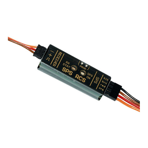
Emcotec DPSI TWIN Mini User manual


DPSI TWIN Mini Operating Instructions Version 1.0
Page 2 of 36
Table of Contents
1. Preface .............................................................................................3
2. Characteristics ................................................................................ 4
2.1. Functional Description.............................................................4
2.2. Safety Considerations & Quality..............................................6
2.3. Connections.............................................................................8
3. Properties of the DPSI TWIN Mini................................................11
3.1. Data Logger...........................................................................12
3.2. Functional Principal of the Switching.....................................13
4. Packing Contents..........................................................................16
5. Mounting Details ...........................................................................16
5.1. Mounting of the DPSI TWIN Mini...........................................16
5.2. Connecting the Receiver .......................................................17
5.3. Arranging the Antennas.........................................................18
5.4. Current Supply and Servo Connections ................................19
5.5. Failsafe Channel....................................................................25
6. Beginning of Operation ................................................................25
7. Error Indications ...........................................................................26
8. Programming.................................................................................27
8.1. Firmware-Update...................................................................29
9. Application Examples...................................................................30
10. Safety Instructions......................................................................32
11. Technical Data of the DPSI TWIN Mini ......................................33
12. Warranty.......................................................................................34

DPSI TWIN Mini Operating Instructions Version 1.0
Page 3 of 36
1. Preface
With the DPSI TWIN MINI you purchased a high grade, modern and
secure product for your valuable radio controlled model. We appreciate
your trust and assure you that you made the right choice!
Long lasting experience for years in development and manufacturing of
electronically systems as well as the knowledge of the world’s best
model airplane pilots has influenced the development of the DPSI
TWIN MINI systems. All products are manufactured at EMCOTEC
GmbH in Germany on our own production line. Extensive optically and
electronically end tests for every system, which leaves our house,
assure that you, our customer, acquire an absolute reliable product
which considerably increases the reliability of your valuable RC-Model.
Of course, the DPSI TWIN MINI not only has been tested extensively
in the laboratory, but also went through intensive flight-testing. Like
done in the automobile industry an FMEA (failure mode and effect
analysis) reduces the possibility of damage and malfunction on
operating errors to a minimum.
Hint:
We kindly ask you to read these instructions carefully and to observe the
installation hints. Thus, errors can be avoided in advance.
We are all ears for your wishes and questions. Challenge us!
Bobingen, September 2007
The Staff of EMCOTEC GmbH

DPSI TWIN Mini Operating Instructions Version 1.0
Page 4 of 36
2. Characteristics
2.1. Functional Description
The DPSI TWIN Mini provides a kind of ”Receiver diversity“. Two
receivers can be connected. The receiver with undisturbed radio
reception provides for the servos signals. If this receiver fails, the
signals for the servos are provided from the other undisturbed receiver
by automatic switch over. Therefore, the model remains fully
controllable if a receiver fails. In summary, 16 channels are switched
completely. The DPSI TWIN Mini can be operated stand-alone or in
conjunction with the battery-switches from then EMCOTEC’s DPSI
product range.
Several applications are possible with the DPSI TWIN Mini:
1. Failsafe-Function “A“:
(Two identical receivers using same frequency)
If one receiver fails, all (!) servos are switched to the second receiver.
The pilot can continue his flight without disturbances or adverse
effects. The receivers should feature a failsafe function (e.g. PCM).
Even by using two PPM (or IPD) receivers without failsafe capability,
switching of the servo signal can occur caused by a disturbed (or
missing) servo signal.
2. Failsafe- Function “B“:
(Two receivers using different frequencies, e.g. using the EMCOTEC HF TWIN)
If one receiver fails OR channel double-allocation occurs, all servos are
switched to the second (backup) receiver.
3. Pilot-Backup:
(Two receivers and two transmitters using different frequencies)
If the receiver OR the transmitter of the pilot fails, all servos are
switched to the second (backup) pilot. He can then land the model
safely.

DPSI TWIN Mini Operating Instructions Version 1.0
Page 5 of 36
4. Teacher-Student-Function:
(Two receivers and two transmitters using different frequencies)
The teacher switches between his and the students radio back and
forth by using a switching channel of his transmitter. The student can
now take over all functions of the model with his transmitter (passing
single functions to the student are not possible). The teacher can gain
full control with one single switching event in critical situations.
Herewith, each model-pilot can fly his friend’s model (which has
installed the DPSI TWIN MINI) with his own radio using his own stick
assignment. He just must program the model parameters into his radio.
5. Autopilot for Drones (UAV´s):
(Regular remote radio control and an autopilot)
The pilot switches between the receiver and the autopilot by using a
switching channel on his radio. The drones therefore can takeoff and
land under control of a regular remote control and be switched to the
autopilot on demand to fly its corresponding program.
Additional Functions:
Additionally, the DPSI TWIN Mini works as data logger, i.e. all
operation relevant data of the last flight are stored in non volatile
memory. The data can be read by a PC afterwards. The cause of an
eventual crash (failsafe signals, number and duration of receiver
disturbances) can be evaluated from the stored information.
Two built in bicolor LED’s indicate optically the operational state of the
DPSI TWIN Mini. In order to receive additional information about the
status of the entire system, the optional DPSI ICE (Information Center),
an external LED or the DPSI LCD can be connected to the DPSI TWIN
Mini.

DPSI TWIN Mini Operating Instructions Version 1.0
Page 6 of 36
2.2. Safety Considerations & Quality
Exclusively highly modern electronically parts are used in the DPSI
TWIN Mini. Electronics are built in as safe as possible in all areas of
the product. All vendor parts such as PCB’s, cables, connectors, etc.
are provided by German companies. The elaborated manufacturing of
the housing provides for best EMC safety, which is especially important
for drones usage. The 4-multilayer PCB allows for highest packing
density and therefore for smallest dimensions and low weight.
Maximum safety is also guaranteed by elaborated software quality
assurance. Individual measuring systems were developed for
qualification, which were used for signal conditioning and analysis.
Thinking about quality continues all the way through manufacturing.
Each step in production is monitored and each system is tested for all
its functions before leaving the house.
Quality over Quantity!
Hint:
The following parameters are factory programmed:
Operating Mode: Failsafe
Fail-Position = 1200µs (ca. –75% of Servo Channel)
Pass-Position = 1800µs (ca. +75% of Servo Channel)
If other parameters are desired, programming is in order (see programming
instructions). The default values best correspond to the +100% and -100%
settings of the failsafe channel of the receiver. Reprogramming of these values is
therefore not mandatory.

DPSI TWIN Mini Operating Instructions Version 1.0
Page 7 of 36

DPSI TWIN Mini Operating Instructions Version 1.0
Page 8 of 36
2.3. Connections
Rear View:
You find pin-connectors at the rear for both receivers (or receiver and
autopilot). There are 16 connectors each for the “main”-receiver as well
as 16 connectors for the “backup”-receiver or autopilot respectively.
The connectors are JR/UNI compatible.
The 16th connector functions as the failsafe-input at the same time
(“FS1” or “FS2”). The failsafe signals of the connected receivers are
evaluated by the DPSI TWIN Mini internally for switch-over. As long as
the signals value is larger than 75% (percentage of the corresponding
servo channels) the receiver is considered error free. As soon as the
signal drops down to less than 75%, the DPSI TWIN Mini recognizes
an error condition (failsafe) and switches all 16 servo signals to the
error free receiver.

DPSI TWIN Mini Operating Instructions Version 1.0
Page 9 of 36
If the failsafe pulses are totally missing or are out of specification, this
is recognized as an error condition too. The 75% values are factory set
and can be reprogrammed at any time.
The receivers are connected to the DPSI TWIN Mini using the
accompanying patch cables.
Hint:
Both connected receivers are supplied by the DPSI TWIN MINI via the patch
cables. The battery connectors of the receivers ALWAYS remain unused!
Front View:
You find the pin connectors of the outputs in the upper row
(connections to servo current distribution or to the servos directly).

DPSI TWIN Mini Operating Instructions Version 1.0
Page 10 of 36
When using a DPSI RV system the patch cables are here connected to
the DPSI. Servos can be directly connected if an optional current
supply is available.
You find in the lower row (from left to right):
AUX1 and AUX2: here, optional products from the EMCOTEC product
range can be connected (LC display, bridging PCB for the DPSI power
part, external sensors for RPM, temperature, height, velocity, etc.).
B1 and B2: connection for the optional DPSI ICE. Furthermore, an
external power supply can be connected, if the DPSI TWIN Mini is to
be used stand-alone (without current distribution), i.e. the servos are
directly connected. For instance, a DPSI BIC, a DPSI LR or a DPSI
Micro can be used as power supply.
EXT: connection for an optional external bicolor LED, which can be
mounted in the fuselage’s sidewall, providing information about the
current status of the DPSI TWIN Mini (see error indications).
COM: connection for the RS232 interface cable to a PC (COM
interface) or using an optional USB convert on an USB port of the PC.
Using the PC software, the parameters of the DPSI TWIN Mini can be
programmed and the data logger can be read. Furthermore, new
firmware can be downloaded.
Opt. Bat: here, an external power supply can be connected if the DPSI
TWIN MINI is being used in the stand-alone version and if the servos
are directly connected. If many servos are to be used, this connection
is to be preferred over the B1 B2 connections. 15A continues current is
possible. The external power supply can be an optional DPSI power
part (contacting a bridging PCB) or a current source ranging from 4.8
volts up to 8.4 volts. Servos and receivers are supplied with this
voltage. Voltages of 5.2 volts up to 6.0 volts are reasonable.

DPSI TWIN Mini Operating Instructions Version 1.0
Page 11 of 36
Hint:
If an external voltage is supplied to “B1” / “B2” or “opt. Bat”, the DPSI TWIN MINI
must not be connected to a servo current distribution!
3. Properties of the DPSI TWIN Mini
Failsafe operation with automatic switching between two receivers
with up to 16 channels each
Teacher student operation with manual switching between two
receivers using a switching channel on radio
“Pilot-Backup" using two separate frequencies possible (2
transmitters, 2 receivers)
Receiver/autopilot switching for drones
All control functions fully available after switching from one receiver
to the other
Failsafe positions freely programmable
Integrated PC interface for reading and programming of the data
and for software updates of the firmware
Data logger, i.e. important parameter of the last 22 (!) flights are
stored and can be read later by a PC
2 x 16 receiver channels
Integrated bicolor LED’s indicate status of the system
Two failsafe channels for evaluation of receiver function
Cable free system, i.e. all connections are pluggable and therefore
replaceable
Special grounding concept for flawless operation and highest safety
Future-proof concept achieved through extendibility (DPSI ICE,
DPSI LCD, DPSI Power, external sensors etc.)
Each system 100% tested prior to delivery

DPSI TWIN Mini Operating Instructions Version 1.0
Page 12 of 36
3.1. Data Logger
The integrated data logger (“black box”) stores all relevant operational
data of 22 turn-on cycles (flights). Each time, the DPSI TWIN Mini is
turned on, a counter is incremented and the data logger advances one
entry. All data of the last 22 flights remain stored and a possible crash
can be analyzed even after some time (or after several turning on
cycles). Usually, one tests the radio right after a crash. This means, the
set is turned on and off several times, before the data is read off of the
data logger at home using the PC.
Due to a turn-on counter, the number of cycles is known (since
purchase of the DPSI TWIN Mini). This provides for the real number of
flights of a model.

DPSI TWIN Mini Operating Instructions Version 1.0
Page 13 of 36
The following data is stored by the data logger:
System-Information:
- Operating Mode (Failsafe or Teaching)
Receiver-Status:
- Number of errors for each receiver (pulse gap greater than
40ms => total malfunction of the receiver)
- Number of errors for each receiver (failsafe, pulse gap
smaller than 10ms, pulse width < 0.8ms, pulse width > 2.2ms
(failsafe only for PCM))
- Time in seconds, where both receivers were in an error condition
simultaneously
The data can provide for exposure of an eventual crash. It is recorded,
if both receivers are failing SIMULTANEOUSLY for e.g. 5 seconds.
This probably causes a model to crash.
3.2. Functional Principal of the Switching
Because two separate receivers are used with the DPSI TWIN Mini, it
must be able to recognize the necessity to switch from the first receiver
(“main”) to the second receiver (“backup”).
This happens based on any receiver output. This output is named
“failsafe output” in this document. For most PCM receivers (Graupner
JR PCM/SPCM as well as Futaba PCM1024), channels 1 through 8
are failsafe capable. Usually, channel 8 is used. Sets from Multiplex do
not use PCM, but rather call it the IPD function. Here too, each IPD
capable channel can be used for failsafe. But even non PCM/IPD
systems can be used with the DPSI TWIN Mini because a total
qualification of the signals takes place and not just only the evaluation
of the failsafe threshold alone.

DPSI TWIN Mini Operating Instructions Version 1.0
Page 14 of 36
The failsafe outputs of both receivers connected to the DPSI TWIN
Mini are constantly monitored for their signal quality. If an error occurs,
this error is qualified after a certain time. A single “one off” does not
lead to switching from one receiver to the other.
For better appreciation, it is helpful to understand how the signals are
provided by the receivers. Most of the remote controls on the market
as of today provide the servos a pulse length coded signal. All approx.
20ms (this is 50 times a second), the receiver sends a pulse to the
servo. Depending on the desired position of the servo, the pulse length
varies between 0.9ms and 2.1ms. In the center position, the pulse
length is 1.5ms, for end positions 0.9ms or 2.1ms respectively. The
DPSI TWIN Mini receives these pulses via the failsafe channels and
evaluates them. The following events are recognized as errors:
Error qualification in DPSI TWIN Mini qualification time
Pulse width is smaller than 0.8ms (100ms)
Pulse width is greater than 2.2ms (100ms)
Pulse gap is smaller than 10ms (100ms)
Pulse gap is greater than 40ms (400ms)
Pulse exceeded failsafe threshold (100ms)
In brackets: error qualification time, i.e. time, after which switching
takes places.
This shows, that also non-PCM-systems can be used, because not
only a certain programmed position (failsafe position) causes a switch
between the two receivers, but also an erroneous signal. If e.g. a
receiver totally fails, it doesn’t provide a signal on its outputs anymore.
The pulse gaps would be greater than 40ms. This is recognized and
switched to the other receiver after a qualification time of 400ms (if this
one works error free).

DPSI TWIN Mini Operating Instructions Version 1.0
Page 15 of 36
If the receiver provides for totally wrong signals (e.g. pulse length
greater than 2.2ms), this is also recognized and causes a switch over.
Switching only occurs, if the second (backup) receiver works error free.
If an error exists in the second receiver as well, no switching occurs.
Hint:
Due to a special algorism, it is impossible that switching occurs rapidly in-
between short intervals (which could lead to signal corruption). Each active
receiver remains active for a minimum period of time before switching can occur
(hysteresis).
Hint:
If switching occurred to the second receiver, this receiver remains active, even if
the first one should become error free.
Hint:
Due to the design of the hardware it is assured, that the servos are NEVER
supplied by both or none receiver. Only ONE receiver is connected to the servos
at any point of time.
Hint:
In order to test switching of the receivers the corresponding failsafe connector
can be pulled out from the DPSI.
If uncertain about the failsafe programming of the transmitter, you can connect a
servo in parallel to the failsafe signal. Now you can monitor the correct
adjustments immediately.

DPSI TWIN Mini Operating Instructions Version 1.0
Page 16 of 36
4. Packing Contents
Content of delivery of the DPSI TWIN Mini
DPSI TWIN Mini base device
20 pieces receiver connection cables (17cm long)
(patch cables with servo connectors on both sides)
=> additional cables available in e-shop
Operating instructions (instructions in English language as
PDF for download from RC-Electronic Homepage)
EMCOTEC adhesive label
5. Mounting Details
5.1. Mounting of the DPSI TWIN Mini
Mounting on 4 silicon hoses has proofed to be the best technical
method. Mount the total packet onto 4 stilts in a shock absorbing
manner.
Mounting using 4pcs. M4 screws with pieces of fuel hoses:

DPSI TWIN Mini Operating Instructions Version 1.0
Page 17 of 36
In general, always watch for vibration free mounting. Vibration damping
is especially important for the receivers, because they are much more
sensitive to mechanically vibrations than the DPSI TWIN Mini.
Holes spacing for mounting:
5.2. Connecting the Receiver
Although the DPSI TWIN Mini provides especially for connecting two
receivers, operation with one receiver (main) is possible. In this case,
the channel connections of the backup receiver will remain unused.
The DPSI TWIN Mini indicates an error for receiver two (backup
receiver) and will show this failure with the build-in LED in this case.
The actual purpose of the device is to connect two receivers. Because
the DPSI TWIN Mini can handle 16 channels, receivers with up to 16
channels can be connected. The failsafe channel is also “fed through”
and therefore is also available for additional functions.

DPSI TWIN Mini Operating Instructions Version 1.0
Page 18 of 36
Of course, not all inputs of the DPSI TWIN Mini must be used. If only 5
channels are needed, 5 patch cables suffice for connecting the DPSI
TWIN Mini to the corresponding receiver (plus failsafe channel).
Hint:
When connecting a second (backup) receiver, all servo outputs must be identical
to the first (main) receiver. This means, no servo outputs must be swapped.
BOTH failsafe inputs of the DPSI TWIN Mini must always be connected, because
error recognition of the corresponding receiver takes place here.
Hint:
If the DPSI TWIN Mini is used in conjunction with an autopilot, the autopilot is
connected instead of the backup receiver. Servo connections must be identical to
the main receiver’s assignment.
5.3. Arranging the Antennas
When defining the positions of the antennas, make sure not to mount
the antennas in parallel. Best is a rod aerial for the mail receiver. Guide
the antenna first in parallel to the fuselage from the receiver, than in
90° to the rod aerial. Don’t change the total length of the antenna. If the
rod aerial is 20 cm / 8”, shorten the receiver’s antenna wire by 20 cm /
8”.
The antenna of the second receiver can either be wired to the elevator,
wired inside the wing (not recommendable due to the plug-in-tube) or
also ending in a rod aerial (eventually down wards). The distance
between the antennas should be as large as possible.

DPSI TWIN Mini Operating Instructions Version 1.0
Page 19 of 36
5.4. Current Supply and Servo Connections
There are several ways to provide power to the equipment. This
depends on connecting the servos directly to the DPSI TWIN Mini or if
the DPSI TWIN Mini is to be used in conjunction with a current
distribution unit (e.g. a DPSI RV).
The most reasonable solution is to use a current distributor (e.g. DPSI
RV Mini 5 or Mini 6, DPSI RV, DPSI 2001 RV or other vendor’s
products).

DPSI TWIN Mini Operating Instructions Version 1.0
Page 20 of 36
DPSI TWIN Mini in connection with DPSI RV Mini 5:
In this example, the DPSI RV Mini is used as a current distributor. The
DPSI TWIN Mini serves just as receiver switch and is supplied with
voltage by the DPSI RV Mini 5 via the patch cables. Both receivers are
supplied from the DPSI TWIN Mini via their patch cables.
Table of contents
Other Emcotec Switch manuals
Popular Switch manuals by other brands
Intelix
Intelix AS-1H1V Installation and operation guide
D-Link
D-Link Web Smart DES-1210-28P reference guide
Raritan
Raritan KX II Frequently asked questions

Viking
Viking FAXJ-300 Technical practice

SMC Networks
SMC Networks ZK2-ZSV-A Series Operation manual
Renkforce
Renkforce RF-3374942 operating instructions
