manuals.online logo
Brands
  1. Home
  2. •
  3. Brands
  4. •
  5. Emcotec
  6. •
  7. Switch
  8. •
  9. Emcotec RC Electronic SPS-RCS User manual

Emcotec RC Electronic SPS-RCS User manual

Remote controlled on-/off switch for the
SPS SafetyPowerSwitch
The SPS-RCS (Remote Control Switch) is a remote
control module for the SPS SafetyPowerSwitch. The SPS
SafetyPowerSwitch can now be turned on and off using a
free receiver channel.
Caution: The SPS-RCS module is an extension for the
EMCOTEC SPS SafetyPowerSwitch and is only usable
with that.
Waldstr. 21
D-86517 Wehringen
Tel.: +49 (0) 8234 / 95 98 9 - 50
Fax: +49 (0) 8234 / 95 98 9 - 59
E-Mail: [email protected]
Safety and warning hints
Please make sure you only turn off the SPS-
RCS when the motor is stopped. When turned off
with motor running, the motor controller can be
destroyed under certain circumstances.
Programming of the SPS-RCS should only take place with
the motor controller disconnected or without any motor at
all. This prevents undesired running of the motor.
If deactivation by failsafe is disabled for the SPS-RCS,
the SPS SafetyPowerSwitch can only be turned off by the
switch of the radio control, see additional information in
Explaining failsafe deactivation.
Quick reference
The SPS-RCS is a remotely controlled electronic on-/off
switch for turning on or off the SPS SafetyPowerSwitch.
If desired the SPS SafetyPowerSwitch can be activated
and deactivated by the SPS-RCS in addition to the SPS
magnetic switch actuator (item no. A72020) or the SPS pin
switch actuator (itme no. A72025).
Mounting instructions
The PCB (Printed Circuit Board) of the SPS-RCS can be
mounted onto an appropriate surface using hook-and-loop
tape or double sided adhesive tape.
Specications
Dimensions 42 x 14 x 9mm (1.65 x 0.55 x 0.35in)
Weight 6.4g (0.23oz)
Warranty 24 months
Connecting
Connect the SPS SafetyPowerSwitches at the socket „SPS“
of the SPS-RCS. Connect socket „RECEIVER“ to a free
receiver channel.
Optionally connect a SPS magnetic switch actuator or a
SPS pin switch actuator at socket „ext. Switch“, so the SPS
SafetyPowerSwitch can be activated or deactivated with the
magnet or pin (see picture 2 page 2).
Please notice the color code on the top side of the SPS-
RCS when connecting the SPS SafetyPowerSwitch (see
picture 1).
Picture 1 - Programming contacts (short circuit bridge)
Programming failsafe deactivation
If the short was reestablished on the contacts of the SPS-
RCS within 5 seconds after programming the on-/off-positi-
on, failsafe deactivation is active, i. e. the connected SPS
SafetyPowerSwitch will be turned off if the servo signals
from the receiver are missing.
While the contacts are still shorted, the LED „RX STAT“ is
turned on in order to signal programming.
If the contacts remain shorted after nished programming,
the LED „RX STAT“ begins to blink after about 5 seconds
(5Hz) until the short is removed again.
After removing the short, programming of the SPS-RCS is
completed and a reset takes place.
Connection Scheme
Picture 2 - Connection scheme
Programming
Programming is only possible within the rst ten seconds
after powering on the SPS-RCS. Afterwards this function is
locked. In case a SPS magnetic switch actuator or a SPS
pin switch actuator is connected, programming only can
take place with a removed magnet or pin.
Programming the Power-On position
• Power up SPS-RCS.
• Put designated switch in transmitter to desired power on
position.
• Short circuit contacts of SPS-RCS (picture 1 page 1) using
e. g. a screwdriver or tweezers. Therefor the shrinking
hose must be punctured.
• The LED „RX STAT“ is on now, the SPS SafetyPowerSwitch
turns on and the selected switch position is stored.
• Put switch in off position, remove short from contacts of
the SPS-RCS, the LED „RX STAT“ turns off after about 1
second. SPS SafetyPowerSwitch turns off, the desired off
position is stored.
• In order to program deactivation by failsafe, reestablish
the short on the contacts again within 5 seconds. For de-
tails of failsafe programming see paragraph Programming
failsafe deactivation.
If no programming of failsafe deactivation is desired, the
programming mode ends here after 5 seconds and a reset
takes place. After programming mode ends, LED „RX STAT“
blinks as long as the switch remains in the off position.
Explaining failsafe deactivation
Missing servo signals from the receiver is a failsafe
situation. Please be aware, that only the servo signals from
the receiver are suppressed when using a SPS magnetic
switch actuator or a SPS pin switch actuator with an inserted
magnet or pin, the power is not removed. An inserted
magnet or pin therefore is equal to a failsafe situation.
This means, the SPS SafetyPowerSwitch can only be turned
off using the magnet or pin, if the failsafe deactivation was
programmed for the SPS-RCS. If the failsafe deactivation
was not programmed, the SPS SafetyPowerSwitch can
only be turned off using the switch of the radio control.
Inserting the magnet or pin does not turn the power off in
this case.

Other Emcotec Switch manuals

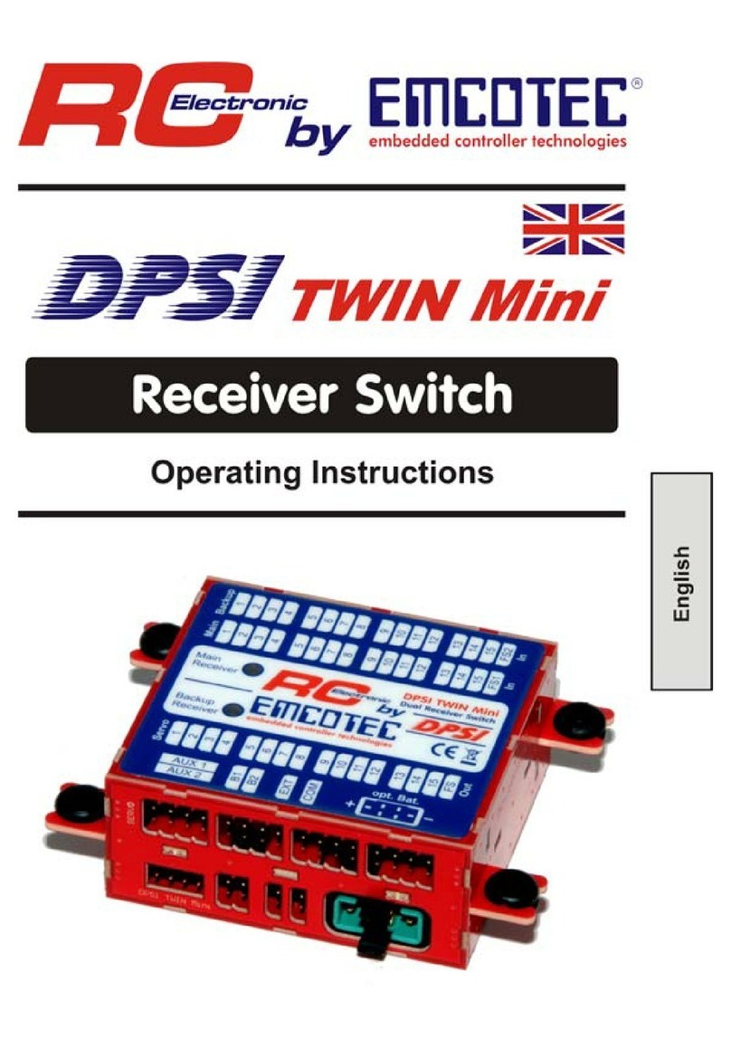
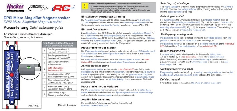
Emcotec iRC Electronic DPSI Micro SingleBat User manual

Emcotec

Emcotec iRC Electronic DPSI Micro SingleBat User manual

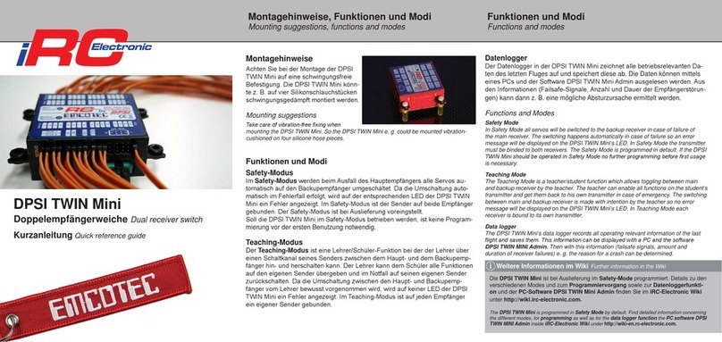
Emcotec iRC Electronic DPSI TWIN Mini User manual

Emcotec

Emcotec iRC Electronic DPSI TWIN Mini User manual

Emcotec DPSI Ampere User manual

Emcotec

Emcotec DPSI Ampere User manual

Emcotec DPSI TWIN Mini User manual

Emcotec

Emcotec DPSI TWIN Mini User manual

Popular Switch manuals by other brands

socomec ATyS d H instruction manual

socomec

socomec ATyS d H instruction manual

Belkin OmniView Secure KVM Switch Specifications

Belkin

Belkin OmniView Secure KVM Switch Specifications

IBM 3454-A3C Customer Install Guide

IBM

IBM 3454-A3C Customer Install Guide

NETGEAR ProSAFE FS526Tv2 installation guide

NETGEAR

NETGEAR ProSAFE FS526Tv2 installation guide

Grandbeing GB07SW0301 operating instructions

Grandbeing

Grandbeing GB07SW0301 operating instructions

Time Gaurd NTT06 Installation & operating instructions

Time Gaurd

Time Gaurd NTT06 Installation & operating instructions

Crestron DigitalMedia XiO Director DM-XIO-DIR-ENT user guide

Crestron

Crestron DigitalMedia XiO Director DM-XIO-DIR-ENT user guide

KinAn RDV108 user manual

KinAn

KinAn RDV108 user manual

Luxul XVS-F5 Quick install guide

Luxul

Luxul XVS-F5 Quick install guide

Truma ZUC manual

Truma

Truma ZUC manual

AVGear AVG-UHS41 DA user manual

AVGear

AVGear AVG-UHS41 DA user manual

Endress+Hauser Flowphant T DTT31 operating instructions

Endress+Hauser

Endress+Hauser Flowphant T DTT31 operating instructions

Siemens SITRANS LVL200E operating instructions

Siemens

Siemens SITRANS LVL200E operating instructions

Panasonic WJ-MPS850 instructions

Panasonic

Panasonic WJ-MPS850 instructions

Dell Z9100-ON installation guide

Dell

Dell Z9100-ON installation guide

GRASS VALLEY PROFILE FAMILY installation manual

GRASS VALLEY

GRASS VALLEY PROFILE FAMILY installation manual

Linksys SR2016 - Cisco - 10/100/1000 Gigabit Switch user guide

Linksys

Linksys SR2016 - Cisco - 10/100/1000 Gigabit Switch user guide

Transition Networks STACKMASTER TR SMHB-TR-16 user manual

Transition Networks

Transition Networks STACKMASTER TR SMHB-TR-16 user manual

manuals.online logo
manuals.online logoBrands
  • About & Mission
  • Contact us
  • Privacy Policy
  • Terms and Conditions

Copyright 2025 Manuals.Online. All Rights Reserved.