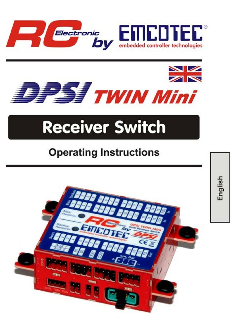
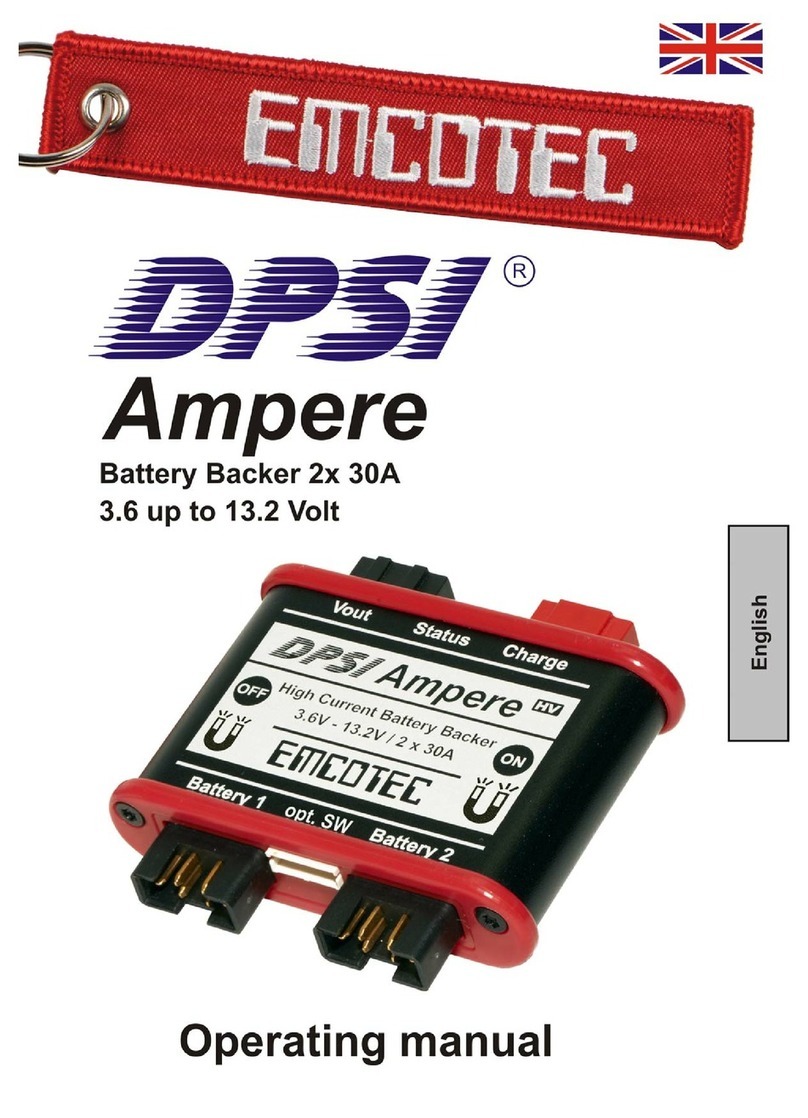
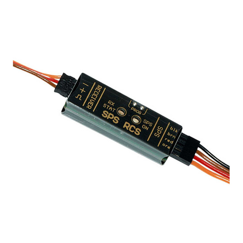
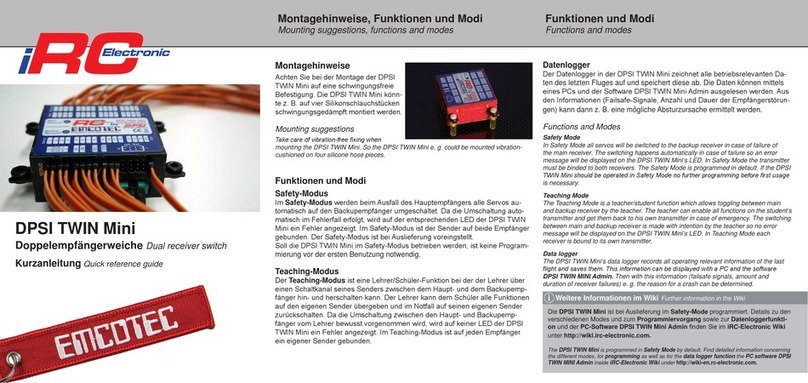
Emcotec iRC Electronic DPSI Micro SingleBat User manual

*Hinweise zum Empfängeranschluss *Notes on the receiver connection
• Es müssen beide Empfängeranschlussabel an den Empfänger angesteckt werden.
Anschluss auch mit V-Kabel an einem Empfängerkanal möglich.
• Both receiver connection cables must be connected to the receiver. Connection also
possible with a Y-cable at one RX channel.
!
Einstellen der Ausgangsspannung
Die Ausgangsspannung des DPSI Micro SingleBat kann auf 5,9 Volt oder
7,2 Volt eingestellt werden. Hierzu muss der Spannungswahlschalter auf der
Gehäuseseite in die gewünschte Position geschoben werden (Abb. 1/3).
Ein- und Ausschalten
Zum Einschalten des DPSI Micro SingleBat muss der mitgelieferte Magnet für
ca. 1 Sekunde über die Einschaltposition (ON) (Abb. 1/6) gehalten werden.
Zum Ausschalten des DPSI Micro SingleBat muss der Magnet für ca. 2 Sekun-
den über die Ausschaltposition (OFF) (Abb. 1/5) gehalten werden. Der Ein- und
Ausschaltvorgang funktioniert durch die Rumpfwand.
Programmiermodus starten
Der Programmiermodus wird gestartet indem innerhalb von 10 Sekunden nach
dem Einschalten der Spannungswahlschalter von der einen in die andere
Position geschoben wird.
Der Programmiermodus wird durch ein 3-sekündiges Leuchten der roten
Status-LED, gefolgt von einer 3-sekündigen Dunkelphase signalisiert.
Akkuprogrammierung
Im Programmiermodus werden auf der roten Status-LED der Reihe nach
Blinkcodes für die entsprechenden Akkutypen, gefolgt von jeweils 3 Sekunden
Pause ausgegeben (Tab. 2 Rückseite). Sobald der gewünschte Akkutyp an-
gezeigt wird, muss der Programmiermodus während der 3-sekündigen Pause
verlassen werden, bevor der nächste Akkutyp durch einen neuen Blinkcode
angezeigt wird.
Programmiermodus verlassen
Der Programmiermodus wird verlassen, indem während der 3-sekündigen
Pause zwischen den Blinkcodes der Spannungswahlschalter erneut betätigt
und wieder in die Ursprungslage zurück geschoben wird.
Ausführliche Anleitung
Die ausführliche Anleitung zum Produkt nden Sie auf
http://wiki.hacker-motor.com
Selecting output voltage
The output voltage of the DPSI Micro SingleBat can be selected to 5.9 volts or
7.2 volts. Therefor the voltage selector at the housing side must be switched
into the desired position (Fig. 1/3).
Switching on and o
For switching on the DPSI Micro SingleBat the included magnet must be
placed over the switching on position (ON) (Fig. 1/6) for approx. 1 second. For
switching o the DPSI Micro SingleBat the magnet must be placed over the
switching o position (OFF) (Fig. 1/5) for approx. 2 seconds. The switching on
and o process works through the fuselage wall.
Starting programming mode
Programming mode can be started by moving the voltage selector from one
position to the other within 10 seconds after switching on.
Programming mode will be indicated by a 3 second turning on of the red status
LED followed by a 3 second o-period of the red status LED.
Battery programming
In programming mode blinking codes for the specic battery type
will be indicated by the red status LED followed by 3 seconds break
(Tab. 2 back side). As soon as the desired battery type is indicated the
programming mode must be quit within 3 seconds in advance of the next
battery type blink code.
Quitting programming mode
Programming mode can be left by by moving the voltage selector into the rst
position again within the 3 second break between the blink codes.
Detailed manual
Find detailed product manual on http://wiki-en.hacker-motor.com
DPSI Micro SingleBat Magnetschalter
DPSI Micro SingleBat Magnetic switch
Kurzanleitung Quick reference guide
Anschluss, Bedienelemente, Anzeigen
Connections, controls, indications
Tab. 1: Anschlüsse, Anzeigen
Tab. 1: Connections, indications
1Empfängeranschluss 1
Receiver connection 1
2Empfängeranschluss 2*
Receiver connection 2*
3Spannungswahlschalter
Voltage selector
4Rote Status LED
Red status LED
5Ausschaltposition (OFF)
Switching o position (OFF)
6Einschaltposition (ON)
Switching on position (ON)
7Anschluss Akku (Bat.)
Connection battery (Bat.)
8Ladebuchse (Chg.)
Charging socket (Chg.)
Abb. 1 Fig. 1 Made in Germany

Fehleranzeige
Auf der roten Status LED wird im Fall der Unterspannung des Akkus eine Feh-
lermeldung angezeigt (Abbildung 2).
Die Fehlermeldungen bleibt bis zum Ausschalten des DPSI Micro SingleBat
aktiv.
Error indication
An error message will be indicated by the red status LED in case of low voltage
of the battery (Picture 2):
The error message stays active until DPSI Micro SingleBat is switched o.
Tab. 3: Technische Daten Tab. 3: Specications
Betriebsspannungsbereich
Operating voltage range
4,8V ... 12V
4.8V ... 12V
Nenneingangsspannung
Nominal voltage
6,0V ... 8,4V
6.0V ... 8.4V
Ausgangsspannung
Output voltage
5,9V oder 7,2V
5.9V or 7.2V
Max. Dauerstrom @ 5,9V (15 Minuten bei LiPo-Akkus)
Max. permanent current @ 5.9V (15 minutes with LiPo batteries) 4A
Max. Dauerstrom @ 7,2V (10 Minuten bei LiPo-Akkus)
Max. permanent current @ 7.2V (10 minutes with LiPo batteries) 6A
Max. Spitzenstrom @ 5,9V (10 Sekunden bei LiPo-Akkus)
Max. peak current @ 5.9V (10 seconds with LiPo batteries) 10A
Max. Spitzenstrom (20ms)
Max. peak current (20ms) 25A
Ausführliche Anleitung
Die ausführliche Anleitung und Technische Daten des Produkts nden Sie auf
http://wiki.hacker-motor.com
Detailed manual
Find detailed product manual and specications on
http://wiki-en.hacker-motor.com
Tab. 2: Blinkcodes/Akkutyp Tab. 2: Blinking code/battery type
Blinkcode
Blinking code
Akkutyp
Battery type
Nennspannung
Nominal voltage
1x Blinken
1x Blink
5 NiCd/NiMH-Zellen
5 NiCd/NiMH cells
6,0V
6.0V
2x Blinken
2x Blink
6 NiCd/NiMH-Zellen
6NiCd/NiMH cells
7,2V
7.2V
3x Blinken
3x Blink
2 LiIon-Zellen
2 LiIon cells
7,2V
7.2V
4x Blinken
4x Blink
2 LiPo-Zellen
2 LiPo cells
7,4V
7.4V
5x Blinken
5x Blink
2 LiFePO4-Zellen
2 LiFePO4 cells
6,6V
6.6V
6x Blinken
6x Blink
7 NiCd/NiMH-Zellen
7 NiCd/NiMH cells
8,4V
8.4V
7x Blinken
7x Blink
Prüfungen deaktivieren
Deactivate test ...
Abb. 2 Fig. 2
Hinweis zur Werkseinstellung Notes on factory default
• Bei Auslieferung ist standardmäßig der Akkutyp 2-Zellen LiPo (4x Blinken) programmiert.
• By default, battery type 2 cell LiPo (4x blink) is programmed at delivery.
!
Kontakt Contact
Hacker Motor GmbH, Schinderstrassl 32, D-84030 Ergolding
Telefon Phone: +49-871-953628-0
eMail eMail: [email protected]
Hacker Motor im Internet Hacker Motor on the Internet
Webseite Website: www.hacker-motor.com
Webshop Webshop: www.hacker-motor-shop.com
Anleitungen Manuals: wiki.hacker-motor.com
YouTube-Kanal YouTube channel: www.youtube.com/HackerMotorGmbH
Facebook-Seite Facebook page: www.facebook.com/HackerMotor
CE-Konformitätserklärung
Hiermit erklärt die Hacker Motor GmbH, dass sich dieses Produkt in
Übereinstimmung mit den grundlegenden Anforderungen und den übrigen
einschlägigen Bestimmungen der EMV-Richtlinie 2014/30/EU bendet.
Die Konformitätserklärung zu diesem Produkt können sie hier anfordern
Hacker Motor GmbH, Schinderstrassl 32, D-84030 Ergolding
oder unter www.hacker-motor.com im Downloadbereich einsehen.
CE Declaration of Conformity (DOC)
Hacker Motor GmbH declares that the product complies with the essential
requirements of the EMC Directive 2014/30/EU.
You can ask for the DOC directly at
Hacker Motor GmbH, Schinderstrassl 32, D-84030 Ergolding
or download at www.hacker-motor.com
Version 3.0 September 2019 Version 3.0 September 2019
Artikel-Nr. Kurzanleitung item no quick reference guide: 19871010
© 2019 Hacker Motor GmbH
Achtung! Attention!
• Der Ausschaltvorgang des DPSI funktioniert mit einem Hallsensor. Hallsensoren reagieren
auf Magnetfelder. Bei sehr starken Magnetfeldern (z. B. Elektroantrieb) kann das DPSI
unter Umständen abschalten. Stromführende Kabel erzeugen ein Magnetfeld. Bitte
verlegen Sie daher alle Kabel, die einen sehr hohen Strom führen (>100A) in einem
Abstand von mindestens 3cm am DPSI vorbei.
• The switching o process of DPSI works with a hall eect sensor. Hall eect sensors can
be inuenced by magnet elds. It is possible that the DPSI switches o when exposed to
a very strong magent eld (i.g. electric drive). Current-carrying cables generate a magnet
eld. So please run all cables which are carrying a high current (>100A) with a distance of
at least 3cm (1.18in) from the DPSI.
!
Other Emcotec Switch manuals
Popular Switch manuals by other brands

HomeMatic
HomeMatic HM-LC-Sw1-Ba-PCB Mounting instruction and operating manual

AVCOMM
AVCOMM 6028GX8-POE Quick installation guide
TRENDnet
TRENDnet TU2-700 - DATA SHEETS Quick installation guide
Force 10
Force 10 E600i TeraScale installation guide
nedis
nedis WIFIPS10 Series quick start guide
Omron
Omron HL-5000 - datasheet
CKD
CKD P1100 instruction manual
CyberData
CyberData 011539 Installation quick reference
Digga
Digga Torque Hub Installation, Operating and Troubleshooting Manual
GE
GE MultiLink ML810 instruction manual
Extreme Networks
Extreme Networks Summit 300-48 Software user's guide

Cables to Go
Cables to Go Port Authority2 user manual
