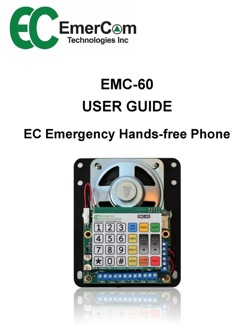
EmerCom Technologies EMCS-OEM User manual

EMCS
USER GUIDE
Emergency Master Control Station
Phone Consolidator

EMCS User Guide
- 2 -
Other Models
EMCS-MR EMCS-OEM

EMCS User Guide
- 3 -
Quick Start Guide
Program Mode (via keypad):
Touch PROG to enter programming mode.
hange parameters by selecting:
< md #> ENTER <value> ENTER
Review parameters by selecting:
< md #> REPLAY
See 6.1 for complete md list
onfigure PLM Groups:
Touch
Select Group # on 24 button keypad
Touch
Icons in selected group light up
Touch icon to toggle to default Grp 1
Touch
ustomer are: all 1-844-EMER OM (1-844-363-7266) for assistance.
Wake unit:
Lift handset and touch to activate
the 24 button keypad
or
all into the EM S-MR from a remote phone
and enter remote programming mode
(see 6.3)
WAKE
ENTER
5
6
1
ENTER
onnect wiring:
ab Phones
Phone lines (TEL 1 and/or 2)
Remote Phones to MR
EM -ALRMs to lobby alarm boards
Video triggers to I/O device
Power (PWR IN)
NiMH battery (BAT)
4
Line test:
Touch . The LINE TEST LED will
turn on and the EM S goes off-hook. Wait
for dial tone then use the keypad to dial a
test number (e.g. a cellphone). Hang-up to
disconnect from the called party ending the
call.
LINE TEST
24 button touch keypad
PLM
Learn Mode:
Touch . If a phone line is detected,
respond to prompt for TEL or Intelli-Split
mode. Otherwise, select LOBBY for internal
calling only. Learn Mode searches for:
ab Phones (Stations)
Phone lines (TEL 1 and/or 2 or None)
LEARN
2
3
PROG
ENTER
ENTER
R
EPLAY

EMCS User Guide
- 4 -
opyright © 2018 by Emer om Technologies Inc
EM S User Guide
ALL RIGHTS RESERVED
NOTICE
The information in this document has been carefully checked and is believed to be accurate. However,
no responsibility is assumed or implied for inaccuracies. Furthermore, Emer om Technologies Inc
reserves the right to make changes to any products herein described to improve reliability, function or
design. Emer om Technologies Inc does not assume liability arising from the application or use of any
product or circuit described herein; neither does it convey any license under its patent rights nor the
rights of others.
This manual and all data contained constitute proprietary information of Emer om Technologies Inc and
shall not be reproduced, copied or disclosed to others, or used as the basis for manufacture without
written consent of Emer om Technologies Inc.
Changes ( .5 to .6)
Cmd 24: CID Update Timer
Cmd 25: Start PLM Test
Cmd 26: PLM check i terval – 0=12 hours; 1= 5hours
Cmd 60: EMCS ID (was Cmd 25)

EMCS User Guide
- 5 -
Contents
1. About the EM S Emergency onsolidator..................................................................................... 7
1.1 Key Features ............................................................................................................................ 7
2. ircuit Board Layout & onnections.............................................................................................. 8
3. Description of Operation: ............................................................................................................. 9
4. Diagnostics ................................................................................................................................. 10
4.1 Learn Mode............................................................................................................................ 10
4.2 Self-diagnostics ...................................................................................................................... 10
4.3 PLM (Phone Line Monitoring) ................................................................................................. 11
4.4 Phone LINE TEST .................................................................................................................... 11
5. Additional Features .................................................................................................................... 12
5.1 Overriding an emergency call ................................................................................................. 12
5.2 System-wide paging (ALL ALL) .............................................................................................. 12
5.3 Internal alling ....................................................................................................................... 12
5.4 Non-emergency off-site calls .................................................................................................. 12
5.5 Video Triggering ..................................................................................................................... 12
6. Programming.............................................................................................................................. 13
6.1 Summary Table ...................................................................................................................... 13
6.2 Programming Details .............................................................................................................. 15
6.2.1 ommand # 1: LEARN MODE .......................................................................................... 15
6.2.2 ommand # 2: OPERATING MODE .................................................................................. 16
6.2.3 ommand # 3: PHONE LINES AVAILABLE ......................................................................... 16
6.2.4 ommand # 4: A TIVE STATIONS .................................................................................... 16
6.2.5 ommand # 5: INA TIVE STATIONS ................................................................................ 16
6.2.6 ommand # 6: SERIAL NUMBER PLAYBA K ..................................................................... 16
6.2.7 ommand # 7: MAIN FIRMWARE VERSION PLAYBA K .................................................... 16
6.2.8 ommand # 8: ALARM STATUS PLAYBA K ...................................................................... 17
6.2.9 ommand # 9: A ESS ODE .......................................................................................... 17
6.2.10 ommand # 10: LANGUAGE ............................................................................................ 17
6.2.11 ommand # 14: AUTO ANSWER...................................................................................... 17
6.2.12 ommand # 23: RING PHONE EXTENSION ....................................................................... 18

EMCS User Guide
- 6 -
6.2.13 ommand # 24: ALLER ID UPDATE TIMER ..................................................................... 18
6.2.14 ommand # 25: START PLM TEST.................................................................................... 18
6.2.15 ommand # 26: PLM HE K INTERVAL ........................................................................... 18
6.2.16 ommand # 30: HANDSET VOLUME SETTING (not EM S-MR) ......................................... 19
6.2.17 ommand # 31: HANDSET MI . SENSITIVITY (not EM S-MR) .......................................... 19
6.2.18 ommand # 32 & # 33: PHONE LINE #1 / #2 BOOST ........................................................ 19
6.2.19 ommand # 34: REMOTE PHONE ATTENUATION ............................................................ 19
6.2.20 ommand # 43: FA TORY RESET ..................................................................................... 19
6.2.21 ommand # 44: REMOTE SILEN E BUZZER ..................................................................... 19
6.2.22 ommands # 50 to # 56: PLM GROUP ASSIGNMENT (EM -MR) ...................................... 20
6.2.23 ommand # 60: EM S ID ................................................................................................ 20
6.3 Remote Programming ............................................................................................................ 21
7. Precautions ................................................................................................................................ 22
8. Mechanical ................................................................................................................................. 23
8.1 Dimensions ............................................................................................................................ 23
9. Keys and Indicators..................................................................................................................... 24
9.1 Keypad ................................................................................................................................... 24
9.2 LEDs and Indicators ................................................................................................................ 25
10. Ordering ..................................................................................................................................... 25
11. Specifications ............................................................................................................................. 26
12. Warranty .................................................................................................................................... 27
13. F Notice and ustomer Information ........................................................................................ 28
14. Industry anada ertification ..................................................................................................... 30

EMCS User Guide
- 7 -
. About the EMCS Emergency Consolidator
. Key Features
ASME A17.1/CSA B44 Safety Code for Elevators requires the mea s to call i to
a y elevator from withi a tall buildi g with elevator travel greater tha 60’ (18m).
The EMCS Co solidator ma ages this operatio through its ha dset a d a y
co ected remote ha dsets, overridi g off-site calls i progress.
I tuitive visual a d audible i dicatio s for system operatio a d call routi g
- Colour-coded touch-co trol ico s i dicate each elevator pho e status
- Voice prompts a ou ce curre t system status to a y ha dset away from
the mai display, either o -site or off-site, with o -site CID display
System-wide page (ALL CALL) from o - or off-site to all elevators
2 co curre t calls to reduce wait time i a broad emerge cy
Ease of setup a d operatio
- "Lear " mode to automatically co figure the system
- Programmable Pho e Li e Mo itori g (PLM) group co figuratio
- “Li e Test” mode to assess the buildi g pho e li e
- Remote pho es ca call off-site
- Bili gual voice prompts
- Touch keypad (Fre ch overlay available)
Adva ced diag ostics
- Built-i Pho e Li e Mo itori g (PLM) from each elevator to the EMCS a d
for each co ected TEL li e as required by Code
- Watchdogs with cou ters for automatic fault recovery a d reporti g
- Remotely simulate alarm call
3 PLM group alarm relays for every 6 cabs (fail safe - closed whe o alarm)
Built-i Video Trigger relay per elevator ( ormally ope ) plus all-clear sig al
“Call A ywhere” (see Call Routes Available o page 2)
Call off-site, via a available pho e li e, usi g a y o -site pho e
Simple SD card firmware upgrades e able feature flexibility with optio al
customizatio
Digital chip platform
Self-diag ostics co ti uously mo itor its ow operatio a d its e viro me t
Compatible with a wide ra ge of power supply voltages (AC a d DC)
Va dal-resista t #16-AWG Brushed Stai less Steel
Box width 14.25" to fit (recess) betwee wall studs
Status a d alarm messages displayed o Remote Pho e CID

EMCS User Guide
- 8 -
2. Circuit Board Layout & Connections
SD CARD
3A FUSE
Fast Acting
EmerCom Technologies Inc.
TEL LINE
HANDSET
DOOR HOOK MR
PWR IN
-BAT+
Battery Specifications:
8.4V NiMH 3800mAh
TO EMC-EXP EMCS-PIM R5
Input Voltage Range:
6VDC-32VDC
6VAC-24VAC
TO EMC-ALRM
VIDEO TRIGGER
TO CABS
2
23+PWR- 6 5 4 3 2RST
TO EMCS-CSM
6 5 4 3 2
analog
phone lines
Remote
handset
(EMC-MR)
elevator
phones
video
triggers to
building
Video
Management
System
PLM-ALRM
group
PLM-ALRM
group 3
16.5Vac SLA
Battery
PLM-ALRM
group 1
Connect
ground wire to
ground lug
RESET
D5

EMCS User Guide
- 9 -
3. Description of Operation:
I the eve t of a e trapme t or other emerge cy, a elevator occupa t may press
the “pho e” butto o the elevator co trol pa el, causi g the elevator pho e to
automatically call for help. I TEL mode the Co solidator routes the call to either of
two pho e li es co ected or to the Co solidator the a pho e li e i seque ce i
I telli-Split mode or to the Co solidator i Lobby mode. The applicable elevator ico
will tur gree .
If the call is ot ack owledged withi a reaso able time, the pho e is required to
automatically ha g up a d dial a seco d pho e umber. If the pho e li e is busy,
the Co solidator will otify the parties o the origi al call that a other call is waiti g.
The Co solidator ca call i to a y of the elevator pho es. The caller selects which
cab by touchi g the appropriate ico which lights-up as soo as the co solidator
door is ope ed. If a ico is illumi ated gree the cab pho e is busy o a call which
ca be overridde by a y of the i -buildi g ha dsets.
Remote/Machi e Room ha dsets ca call i to a y cab, eve overridi g emerge cy
calls or joi i g a other i ter al call i progress.
ALL CALL (system-wide pagi g) is available from all i ter al ha dsets as well as
from off-site.
Pho e Li e Mo itori g (PLM) verifies the operatio of the exter al pho e li es as
well as the li es from each cab. Cabs are assig ed to groups usi g the quick
program keys, with 3 group alarm relays available for every 6 cabs. Each relay
sig als the appropriate EMC-ALRM board. Group “0” pho es do ot activate PLM
alarms.
Video trigger relays i dicate whe ever a emerge cy call from a cab is i progress.

EMCS User Guide
- 10 -
4. Diagnostics
4. Learn Mode
Lear mode automatically validates the wired commu icatio s system a d co figures
the operati g mode selected by the user.
Detects the umber a d positio of active cabs wired to the Co solidator
Verifies the operati g mode selected (TEL, Lobby or I telli-Split) by detecti g the
umber of valid pho e li es wired to the system
Automatically co figures EMC-60 pho es “Co solidator Compatibility” mode
I the case of a y elevator pho e exhibiti g u usual behaviour the
correspo di g cab ico illumi ates “RED” to flag the pho e as “Faili g to
Co ect”. Note: “Failing to Connect” followed by a second attempt to
communicate will generate a PLM alarm unless the elevator phone is assigned to
PLM group #0
4.2 Self-diagnostics
The Co solidator co ti uously mo itors the operatio of the commu icatio s system,
reporti g call routi g status, pho e li e availability a d a y alarm co ditio s. These
co ditio s ca be observed o the display at the Co solidator or the CID display of a
o -site remote ha dset or heard by lifti g the co solidator ha dset a d touchi g
<ALARM STATUS>, or remotely through programmi g mode.
Routi g status prompts
o Statio #x is i co versatio
o No available pho e li es
o Pho e li e #y is u available
o Off-site ALL CALL i progress
Alarm co ditio s:
o Normal
o No mai s power
o No battery
o Low battery
o Chargi g battery
o Fault battery
o Pho e li e fault
o Statio # fault
o PLM fault

EMCS User Guide
- 11 -
Problem Al rm LED
st tus
Buzzer
st tus
No mains power
POWER
FLASHING
Alert
every 0.5 s
Battery issue (check ALARM STATUS) BATTERY FLASHING Alert every 0.5 s
No cab phone response in 24hours STATION I ON RED Alert every 30 s
Any of the expected phone lines not operational
(TEL mode) PHONE LINE RED Alert every 0.5 s
No cab phone response in 24hours (if phone not
group 0)
All expected phone lines not operational (TEL Mode)
PLM RED Alert every 30 s
4.3 PLM (Phone Line Monitoring)
The Pho e Li e Mo itori g (PLM) feature verifies the operability of the e d-to-e d
commu icatio s li k (e.g. for elevator pho e co ecti g to a live pho e li e) as required
by ASME A17.1/CSA B44 Code. A y fault detected ge erates a audible a d visual
alert i the elevator lobby for the assig ed group (elevator pho es assig ed to group #0
will ot ge erate a PLM alarm). I a alarm state the commu icatio li k is re-tried
every five mi utes u til the failed status is cleared.
4.4 Phone LINE TEST
A pho e LINE TEST feature e ables o -site perso el who have access to the
co solidator keypad to go off-hook, liste for dial to e a d call a y umber to test the
pho e li e operability. A similar off-site calli g feature is available from a y o -site
remote ha dset.

EMCS User Guide
- 12 -
5. Additional Features
5. Overriding an emergency call
The Co solidator overrides off-site calls i accorda ce with ASME A17.1/CSA B44
“Safety Code for Elevators a d Escalators”. Lift the ha dset a d touch the ico
correspo di g to the active off-site co versatio (illumi ated i GREEN). The ha dset
will take over the existi g co versatio , co ecti g directly to the elevator pho e after
otifyi g all parties before overridi g the off-site co ectio .
O -site remote pho es ca also override off-site co versatio s by followi g the
selectio prompts. If a o -site co versatio is i progress, subseque t o -site
ha dsets will joi the active co versatio .
5.2 System-wide paging (ALL CALL)
The all system page (ALL CALL) is available by diali g i from off-site or it ca origi ate
from o -site usi g either the ha dset a d touchpad or by followi g the voice prompts
usi g a y remote/o -site pho e. O ce co ected, the operator ca broadcast to all
elevator pho es simulta eously. O -site i itiated calls have a higher priority tha those
origi ati g from off-site a d override (similar to the process described i 5.1).
5.3 Internal Calling
Remote pho es ca call the Co solidator by followi g the exte ded voice selectio
prompts – providi g a co ve ie t feature whe commu icati g from a machi e room
where cellpho e service is u available to a “helper” i the lobby.
5.4 Non-emergency off-site calls
A y i ter al pho e (the EMCS ha dset or a y remote pho e) ca be used to call off-
site i case of a emerge cy or for Customer Care (1-844-363-7266) via a available
pho e li e. Note: The Consolidator considers these calls to have non-emergency
priority which are automatically overridden by calls initiated by entrapment events.
5.5 Video Triggering
The Co solidator has o e pair of pote tial-free, ormally ope co tacts for each cab
pho e, which close duri g a emerge cy call to sig al a video ma ageme t system to
display/record the video as required. A additio al relay co tact closes whe there are
o emerge cy calls i progress.
Note: Not activated during “Learn”, “PLM check” or “ALL CALL”.

EMCS User Guide
- 13 -
6. Programming
6. Summary Table
The followi g sectio 6.2 provides more detailed i formatio o each comma d.
Cmd # Command Range Default
1 Lear Mode
- prompted to select
Operati g Mode
0 = Lobby Mode (automatic if o pho e
li es are available)
1 = TEL Mode (if 1 or 2 pho e li es)
2 = I telli-Split (if 1 or 2 pho e li es)
N/A
2 Operati g Mode 0 = Lobby Mode
1 = TEL Mode
2 = I telli-Split Mode
1
3 Pho e Li es Available 1 digit; values 0,1,2 1
4 Active Statio s 0 – 6 (or 1-12 with EMCS-EXP) 1,2
5 I active Statio s 0 – 6 (or 1-12 with EMCS-EXP) 3,4,5,6
6 Serial Number Playback Replay o ly Pre-set
7 Mai Firmware Versio Replay o ly Pre-set
8 Alarm Status Playback Replay o ly, o e or more of the followi g
“NO MAINS POWER”
“NO BATTERY”
“LOW BATTERY”
“CHARGING BATTERY”
“NORMAL”
“PHONE LINE FAULT”
“STATION NUMBER # FAULT”
N/A
9 Access Code 5 digits; values 1,2,3,4,5,6,7,8,9,0 12345
10 La guage 0 = E glish
1 = Fre ch
0
14 Auto A swer 0 = OFF (ig ore i comi g o pho e li e)
1 = ON
1

EMCS User Guide
- 14 -
Cmd #
Command
Range
Default
23 Ri g Pho e Exte sio 0 = OFF (i comi g will ot ri g remote)
1 = ON (remote pho e ri gs o i comi g
call – required for CID alarm display)
0
24 Caller ID Update Timer 1-30 mi utes (alarm reporti g freque cy)
1
25 Start PLM Test 1 = CONFIRM N/A
26 PLM Check I terval 0 = 12 hours
1 = 5 hours
0
30 Ha dset Volume Setti g 0 = soft, 9 = loud 5
31 Ha dset Mic. Se sitivity 0 = least se sitive; 9 = most se sitive 5
32 TEL1 Li e boost 0 = mi ; 9 = max boost 2
33 TEL 2 Li e boost 0 = mi ; 9 = max boost 2
34 Rem. Pho e atte uatio 0 = mi .; 8 = max atte uatio 4
43 Factory Reset 1 = CONFIRM N/A
44 Remote Sile ce Buzzer 1 = CONFIRM N/A
45 PIM Firmware Versio Replay o ly Pre-set
46 CSM Firmware Versio Replay o ly Pre-set
47 CSM Hardware Versio Replay o ly Pre-set
50 PLM Group 0 (OFF) 1-6 (or 1-12 with EMCS-EXP) -
51 PLM Group 1 1-6 (or 1-12 with EMCS-EXP) default All cabs
52 PLM Group 2 1-6 (or 1-12 with EMCS-EXP) -
53 PLM Group 3 1-6 (or 1-12 with EMCS-EXP) -
54 PLM Group 4 (o ly with EMCS-EXP) 1-12 -
55 PLM Group 5 (o ly with EMCS-EXP) 1-12 -
56 PLM Group 6 (o ly with EMCS-EXP) 1-12 -
60 EMCS ID 0-9 (set > 0 if more tha o e EMCS) 0

EMCS User Guide
- 15 -
6.2 Programming Details
Lift the ha dset a d touch <WAKE> to tur o the keypad a d illumi ate the “WAKE”
LED or call i to the Co solidator from a remote locatio (o - or off-site) (see ext
sectio for remote programmi g). Touch <PROG> to e ter program mode a d tur -o
the “PROG” LED. The operator prompt “Program” will be heard.
Touch the key(s) to select the comma d umber required, touch <ENTER> a d liste
for the prompt to co firm the comma d. I put the parameter a d touch <ENTER>. The
prompt “Input accepted” will be heard if the parameter qualifies or “Incorrect entry,
please re-enter” if ot. To check a y e try, touch the comma d umber followed by
<REPLAY>. Touch <CANCEL> to exit a comma d without cha gi g the parameter.
Touch <EXIT> or ha g-up the ha dset to leave programmi g mode. A audible alarm
will sou d if the ha dset is off-hook too lo g without activity.
REPLAY
To check the curre t value of a y parameter, e ter the comma d umber followed by
the <REPLAY> key. For example, to hear the mai firmware versio , press the <7> key
followed by <REPLAY>. O e will the hear the message “Firmware version” followed by
the digits represe ti g the firmware versio i stalled o your u it.
6.2.1
Command # : LEARN MODE
Lear mode automatically co figures a d verifies the wired commu icatio system. The
Co solidator first checks the umber of valid pho e li es wired to the system a d
a ou ces the operati g modes available for selectio . The the Co solidator searches
for all cab pho es co ected to the system a d displays the status of each pho e as a
colour o the correspo di g statio ico s. Cabs which exhibit u acceptable behaviour
are flagged RED for failed a d trigger a Pho e Li e Mo itori g (PLM) alarm i their
group.
E ter Lear Mode through the programmi g me u or by touchi g the <LEARN>
shortcut key. The voice prompt “Learn Mode” will be heard, followed by a choice of
available operati g modes based o the wiri g co figuratio . Touch the digit
correspo di g to the desired mode followed by <ENTER> to co firm. The voice prompt
“Configuration complete” will be a ou ced at the e d of the process. Ha g-up.
Voice Prompt: “Learn mode”

EMCS User Guide
- 16 -
6.2.2
Command # 2: OPERATING MODE
The Co solidator routes co versatio s accordi g to site requireme ts. I “Lobby mode”,
emerge cy calls from the cabs are directed to all i -buildi g “authorized perso el”
ha dset locatio s. “TEL mode” directs calls off-site via the wired pho e li e(s). I
“I telli-split mode”, emerge cy calls are directed to either i -buildi g or off-site
“authorized perso el” locatio s, depe di g o li e availability.
Voice Prompt: “Operating mode”
6.2.3
Command # 3: PHONE LINES AVAILABLE
This sets the umber of valid pho e li es wired to the system. The “Learn mode” auto-
co figuratio setti g ca be overridde ma ually.
Voice Prompt: “Phone lines available”
6.2.4
Command # 4: ACTIVE STATIONS
The statio umbers of active cabs are assig ed usi g this comma d. I put each
statio umber to be activated followed by <ENTER> or touch <REPLAY> to hear a list
of all cabs curre tly assig ed. The “Learn mode” auto-co figuratio setti g ca be
overridde ma ually.
Voice Prompt: “Active stations”
6.2.5
Command # 5: INACTIVE STATIONS
Use this comma d to u assig cabs by i putti g the statio umber followed by
<ENTER> or touch <REPLAY> to hear a list of i active cabs. The “Learn mode” auto-
co figuratio setti g ca be overridde ma ually.
Voice Prompt: “Inactive stations”
6.2.6
Command # 6: SERIAL NUMBER PLAYBACK
Factory set. Use the serial umber playback comma d to report the serial umber (as
displayed o the sticker attached to the mai circuit board).
Voice Prompt: “Serial number”
6.2.7
Command # 7: MAIN FIRMWARE VERSION PLAYBACK
Replays the Co solidator’s mai circuit board firmware versio .
Voice Prompt: “Firmware version”

EMCS User Guide
- 17 -
6.2.8
Command # 8: ALARM STATUS PLAYBACK
The <ALARM STATUS> touch key a d “Alarm Status Playback” comma d report the
system alarm status (power, battery, TEL li e a d cab pho e co ditio ).
Voice Prompt: “Alarm status”
Note: The battery is a rechargeable NiMH battery and should have a full charge within 1
day of connecting the Consolidator to AC power Replace with a factory-supplied battery
if the alarm status indicates a dead battery or once every 5 years
6.2.9
Command # 9: ACCESS CODE
E try of a 5-digit access code will be required for remote programmi g. Cha gi g the
access code to a u ique umber will preve t others calli g i a d modifyi g the
setti gs. Default is 2 3 4 5.
Caution: Programming by calling in remotely will not be possible without the access
code
Voice Prompt: “Access code”
6.2.10
Command # 0: LANGUAGE
The Co solidator has built-i voice prompts to assist emerge cy perso el whe a
emerge cy call is i progress a d to assist duri g programmi g. Set to either E glish
(0) or Fre ch (1).
Voice Prompt: “Language”
6.2.11
Command # 4: AUTO ANSWER
The auto a swer setti g determi es whether the Co solidator accepts off-site calls from
either pho e li e.
Voice Prompt: Auto answer”

EMCS User Guide
- 18 -
6.2.12
Command # 23: RING PHONE EXTENSION
This comma d e ables sig ali g from the Co solidator to o -site remote locatio s.
Whe tur ed o , remote pho es attached to the MR termi al will ri g a d display
emerge cy call a d alarm status i formatio o the CID scree .
Voice Prompt: “Ring phone extension”
6.2.13
Command # 24: CALLER ID UPDATE TIMER
Alarm status i formatio is displayed o every o -site remote pho e CID scree a d
updated at i tervals defi ed by this timer (i mi utes).
Voice Prompt: Caller ID update timer”
6.2.14
Command # 25: START PLM TEST
To simulate a cab pho e failure, set the PLM test o the EMC-60 cab pho e
(Comma d 24) to 1 - 100s, which de-e ergize the PLM alarm relay for the time
selected. Start the EMCS PLM test (touch 1 to co firm) to activate the alarm.
The EMCS will check the status every mi ute u til the EMC-60 PLM alarm resets.
Voice Prompt: “PLM test”
6.2.15
Command # 26: PLM CHECK INTERVAL
The ‘PLM Check I terval’ sets the test freque cy (Code requires at least o ce per day)
Whe PLM Check Interval = 0, the EMCS executes a full PLM check every 12 hours.
Whe PLM Check Interval = 1, the EMCS executes a full PLM check every 5 hours.
Voice Prompt: “PLM check interval”

EMCS User Guide
- 19 -
6.2.16
Command # 30: HANDSET VOLUME SETTING (not EMCS-MR)
The “Volume Setti g” comma d sets the volume of the Co solidator ha dset speaker.
Voice Prompt: “Volume”
6.2.17
Command # 3 : HANDSET MIC. SENSITIVITY (not EMCS-MR)
This sets the Co solidator ha dset micropho e se sitivity. 0 = least se sitive; 9 = most
se sitive.
Voice Prompt: BEEP”
6.2.18
Command # 32 & # 33: PHONE LINE # / #2 BOOST
“Pho e Li e Boost” will amplify the sig al for soft/quiet pho e li es.
Co tact Customer Care (1-844-363-7266) for additio al i formatio .
Voice Prompt: “BEEP”
6.2.19
Command # 34: REMOTE PHONE ATTENUATION
For commu icatio from “ oisy” Machi e Rooms, “Remote Pho e Micropho e
Atte uatio ” reduces the ha dset micropho e path volume to the elevator pho e to
reduce “choppi g” a d improve 2-way commu icatio .
Voice Prompt: BEEP”
6.2.20
Command # 43: FACTORY RESET
All parameters are reset to factory default. E ter <1> to co firm.
Voice Prompt: Factory parameters reset”
6.2.21
Command # 44: REMOTE SILENCE BUZZER
“Remote Sile ce Buzzer” will remotely mute the Co solidator buzzer a d the CID
alarms. (or sile ce the buzzer with the “sile ce” butto o the co solidator)
Voice Prompt: Silence buzzer”

EMCS User Guide
- 20 -
6.2.22
Commands # 50 to # 56: PLM GROUP ASSIGNMENT (EMC-MR)
Comma d #50 allocates the cab specified (1-12) to group 0 ( o alarm).
Comma d #51 allocates the cab specified (1-12) to group 1 (default).
Comma d #52 allocates the cab specified (1-12) to group 2.
Comma d #53 allocates the cab specified (1-12) to group 3.
Comma d #54 allocates the cab specified (1-12) to group 4.
Comma d #55 allocates the cab specified (1-12) to group 5.
Comma d #56 allocates the cab specified (1-12) to group 6.
Examples: To allocate cab #4 to PLM group #2, i programmi g mode,
touch 52 <ENTER> 4 <ENTER>.
Touch 52 <REPLAY> to list all cabs assig ed to group 2.
All cabs are assig ed to Group #1 by default a d eed to be pulled to their ew Group.
Cabs assig ed to Group #0 are ig ored by the daily PLM check.
Voice Prompt: “PLM Group”
6.2.23
Command # 60: EMCS ID
A u ique ID must be assig ed to each Co solidator if more tha o e are co ected i
the system. Use default ID = 0 for systems with o ly o e Co solidator.
Voice Prompt: EMCS ID”
This manual suits for next models
2
Table of contents
Other EmerCom Technologies Emergency Phone manuals