Emerson ControlWave EFM 3808 User manual

www.EmersonProcess.com/Remote
Instruction Manual
CI-ControlWave Express
Part: D301386X012
March, 2011
ControlWave Ex
p
ress
ControlWave Express
(Remote Terminal Unit)
RemoteAutomation Solution
s

IMPORTANT! READ INSTRUCTIONS BEFORE STARTING!
Be sure that these instructions are carefully read and understood before any operation is
attempted. Improper use of this device in some applications may result in damage or injury. The
user is urged to keep this book filed in a convenient location for future reference.
These instructions may not cover all details or variations in equipment or cover every possible
situation to be met in connection with installation, operation or maintenance. Should problems arise
that are not covered sufficiently in the text, the purchaser is advised to contact Emerson Process
Management, Remote Automation Solutions division (RAS) for further information.
EQUIPMENT APPLICATION WARNING
The customer should note that a failure of this instrument or system, for whatever reason, may
leave an operating process without protection. Depending upon the application, this could result in
possible damage to property or injury to persons. It is suggested that the purchaser review the
need for additional backup equipment or provide alternate means of protection such as alarm
devices, output limiting, fail-safe valves, relief valves, emergency shutoffs, emergency switches,
etc. If additional information is required, the purchaser is advised to contact RAS.
RETURNED EQUIPMENT WARNING
When returning any equipment to RAS for repairs or evaluation, please note the following: The
party sending such materials is responsible to ensure that the materials returned to RAS are clean
to safe levels, as such levels are defined and/or determined by applicable federal, state and/or
local law regulations or codes. Such party agrees to indemnify RAS and save RAS harmless from
any liability or damage which RAS may incur or suffer due to such party's failure to so act.
ELECTRICAL GROUNDING
Metal enclosures and exposed metal parts of electrical instruments must be grounded in
accordance with OSHA rules and regulations pertaining to "Design Safety Standards for Electrical
Systems," 29 CFR, Part 1910, Subpart S, dated: April 16, 1981 (OSHA rulings are in agreement
with the National Electrical Code).
The grounding requirement is also applicable to mechanical or pneumatic instruments that
include electrically operated devices such as lights, switches, relays, alarms, or chart drives.
EQUIPMENT DAMAGE FROM ELECTROSTATIC DISCHARGE VOLTAGE
This product contains sensitive electronic components that can be damaged by exposure to an
electrostatic discharge (ESD) voltage. Depending on the magnitude and duration of the ESD, this
can result in erratic operation or complete failure of the equipment. Read supplemental document
S14006 for proper care and handling of ESD-sensitive components.
Remote Automation Solutions
A Division of Emerson Process Management
1100 Buckingham Street, Watertown, CT 06795
Telephone (860) 945-2200

Emerson Process Management
Training
GET THE MOST FROM YOUR EMERSON
INSTRUMENT OR SYSTEM
Avoid Delays and problems in getting your system on-line
Minimize installation, start-up and maintenance costs.
Make the most effective use of our hardware and software.
Know your system.
As you know, a well-trained staff is essential to your operation. Emerson offers a full
schedule of classes conducted by full-time, professional instructors. Classes are offered
throughout the year at various locations. By participating in our training, your personnel
can learn how to install, calibrate, configure, program and maintain your Emerson products
and realize the full potential of your system.
For information or to enroll in any class, go to http://www.EmersonProcess.com/Remote and
click on “Educational Services” or contact our training department in Watertown at (860)
945-2200.

This page is intentionally left blank

ControlWave Express Instruction Manual (CI-ControlWave Express)
Issued Mar-2011 Contents v
Contents
Chapter 1 – Introduction 1-1
1.1 Scope of the Manual.................................................................................................................1-2
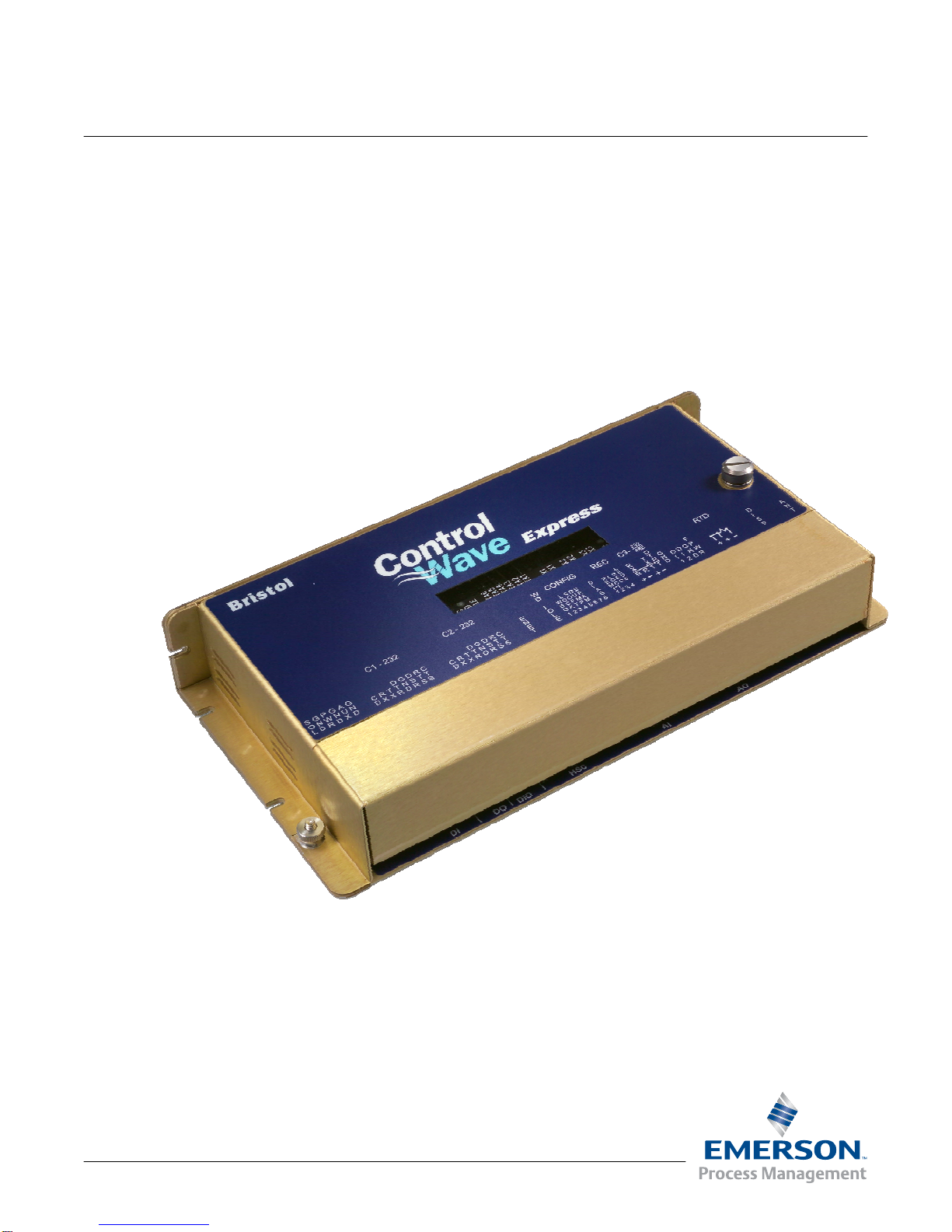
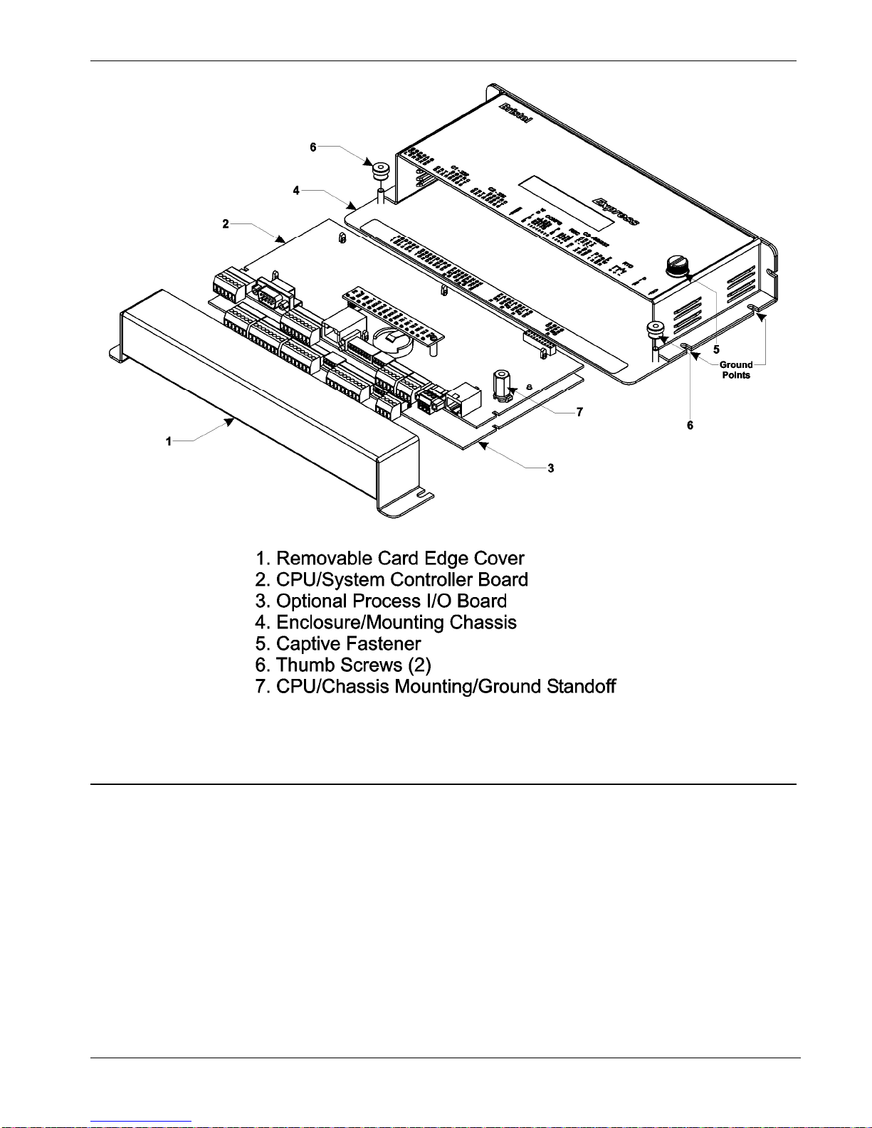
1.2 Physical Description..................................................................................................................1-2
1.3 CPU/System Controller Board ..................................................................................................1-3
1.4 Power Options...........................................................................................................................1-5
1.5 I/O Options................................................................................................................................1-5
1.6 Software Tools ..........................................................................................................................1-6
Chapter 2 – Installation 2-1
2.1 Site Considerations...................................................................................................................2-1
2.1.1 Class I, Div 2 Installation Considerations......................................................................2-3
2.2 Installation Overview.................................................................................................................2-3
2.2.1 Unpacking Components................................................................................................2-4
2.2.2 Mounting the Housing...................................................................................................2-4
2.2.3 Grounding the Housing.................................................................................................2-6
2.3 Configuring the CPU/System Controller Board.........................................................................2-7
2.3.1 Setting DIP Switches on the CPU/System Controller Board ........................................2-8
2.3.2 Setting Jumpers on the CPU/System Controller Board..............................................2-10
2.3.3 General Wiring Guidelines..........................................................................................2-11
2.3.4 Wiring Power to the CPU/System Controller Board....................................................2-11
2.3.5 Connections to RS-232 Serial Port(s) on the CPU/System Controller Board.............2-14
2.3.6 Connections to the COM3 (RS-485/RS-232) Serial Port on the CPU/System Controller
Board .........................................................................................................................2-19
2.3.7 Connections to the Ethernet Port on the CPU/System Controller Board....................2-21
2.4 Optional Display/Keypads.......................................................................................................2-22
Chapter 3 – I/O Configuration and Wiring 3-1
3.1 I/O Options................................................................................................................................3-1
3.2 Process I/O Board.....................................................................................................................3-2
3.2.1 Setting Jumpers on the Process I/O Board...................................................................3-2
3.2.2 Setting DIP Switches on the Process I/O Board...........................................................3-2
3.3 I/O Wiring ..................................................................................................................................3-4
3.3.1 Non-Isolated Discrete Inputs (DI) on TB2 and TB3 of Process I/O Board....................3-6
3.3.2 Non-Isolated Discrete Outputs (DO) on TB3 of Process I/O Board..............................3-7
3.3.3 Non-Isolated Analog Inputs (AI) on TB6 of Process I/O Board.....................................3-8
3.3.4 Non-Isolated Analog Output (AO) on TB7 of Process I/O Board..................................3-9
3.3.5 Non-Isolated Pulse Counter/Discrete Inputs on TB5 of CPU/System Controller Bd..3-10
3.3.6 Non-Isolated High Speed Counter (HSC) / Discrete Inputs (DI) on TB4 of Process I/O
Board .........................................................................................................................3-11
3.3.7 Resistance Temperature Device (RTD) Inputs on CPU/System Controller Board.....3-12
3.3.8 Connections to a Bristol Model 3808 Transmitter.......................................................3-14
Chapter 4 – Operation 4-1
4.1 Powering Up/Powering Down the ControlWave Express .........................................................4-1
4.2 Communicating with the ControlWave Express........................................................................4-2
4.2.1 Default Comm Port Settings..........................................................................................4-2
4.2.2 Collecting Data from the ControlWave Express............................................................4-2
4.3 Creating and Downloading an Application (ControlWave Project) ...........................................4-3

ControlWave Express Instruction Manual (CI-ControlWave Express)
vi Contents Issued Mar-2011
4.4 Creating and Maintaining Backups...........................................................................................4-3
4.4.1 Creating a Zipped Project File (*.ZWT) For Backup.....................................................4-4
4.4.2 Saving Flash Configuration Parameters (*.FCP)..........................................................4-5
4.4.3 Backing up Data............................................................................................................4-6
Chapter 5 – Service and Troubleshooting 5-1
5.1 Upgrading Firmware..................................................................................................................5-2
5.2 Removing or Replacing Components.......................................................................................5-5
5.2.1 Accessing Modules for Testing.....................................................................................5-5
5.2.2 Removing/Replacing the CPU/System Controller Board and the Process I/O Board..5-5
5.2.3 Removing/Replacing the Backup Battery.....................................................................5-6
5.2.4 Enabling / Disabling the Backup Battery.......................................................................5-7
5.3 General Troubleshooting Procedures.......................................................................................5-8
5.3.1 Checking LEDs .............................................................................................................5-8
5.4 WINDIAG Diagnostic Utility.....................................................................................................5-12
5.4.1 Available Diagnostics..................................................................................................5-13
5.5 Core Updump..........................................................................................................................5-16
5.6 Calibration Checks..................................................................................................................5-17
Appendix A – Special Instructions for Class I, Division 2 Hazardous Locations A-1
Appendix Z – Sources for Obtaining Material Safety Data Sheets (MSDS) Z-1
Index IND-1

ControlWave Express Instruction Manual (CI-ControlWave Express)
Revised Mar-2011 Introduction 1-1
Chapter 1 – Introduction
This manual focuses on the hardware aspects of the ControlWave
Express Remote Terminal Unit (RTU). For information about the
software used with the ControlWave Express, refer to Getting Started
with ControlWave Designer (D5085), the ControlWave Designer
Programmer’s Handbook (D5125), and the online help in ControlWave
Designer.
This chapter provides an overview of the ControlWave Express and its
components and details the structure of this manual
In This Chapter
1.1 ........................................................................1-2Scope of the Manual
1.2 ........................................................................1-2Physical Description
1.3 .........................................................1-3CPU/System Controller Board
1.4 .................................................................................1-5Power Options
1.5 .......................................................................................1-5I/O Options
1.6 .................................................................................1-6Software Tools
ControlWave Express is designed to perform as the ideal platform for
remote site automation, measurement, and data management in process
control and manufacturing. Typical process inputs used by the
ControlWave Express are pressure, flow, level, temperature and
frequency input [typically used for positive displacement (PD)], turbine,
or ultrasonic meters. In some cases, inputs may also be derived from
external multivariable transmitters using either the BSAP or Modbus
protocols. When mounted in a suitable enclosure, you can operate the
ControlWave Express in a protected outdoor environment.
Features ControlWave Express has the following key features:
Exceptional performance and low power consumption through use
of the ARM microprocessor
Very low power consumption to minimize costs of solar panel /
battery power systems
Three CPU / System Controller board configurations (see Table 1-
1.)
Three process I/O board configurations (see Table 1-2.)
Small size (enabling panel- or DIN-rail mounting installations)
Two RS-232 and one RS-232/RS-485 asynchronous serial
communication ports
Optional 10/100 MB Ethernet port
Optional Display/Keypad
Wide operating temperature range: (–40 to +70C) (–40 to 158F)
Battery backup for Static RAM (SRAM) and real-time clock.

ControlWave Express Instruction Manual (CI-ControlWave Express)
1-2 Introduction Revised Mar-2011
Nonincendive Class I, Division 2 (Groups A, B, C and D)
Hazardous Location approvals when installed in a suitable enclosure
- see Appendix A.
Cost-effective for small RTU/process controller applications.
1.1 Scope of the Manual
This manual contains the following chapters:
Chapter 1
Introduction Provides an overview of the hardware and
general specifications for the ControlWave
Express.
Chapter 2
Installation Provides information on mounting the
ControlWave Express and setting CPU jumpers
and switches.
Chapter 3
I/O Configuration Provides general information on wiring the
process I/O points.
Chapter 4
Operation Provides information on day-to-day operation of
the ControlWave Express.
Chapter 5 Service and
Troubleshooting Provides information on service and
troubleshooting procedures.
1.2 Physical Description
The ControlWave Express consists of a CPU/System Controller Board
(SCB) with a piggy-back mounted LED board, an optional process I/O
board, and a two-piece enclosure. The enclosure consists of a card-edge
cover and a mounting chassis.
You can loosen the two thumb screws to remove the card edge cover
and access the instrument field wiring.
You can purchase an optional LCD display to provide runtime status
information.

ControlWave Express Instruction Manual (CI-ControlWave Express)
Figure 1-1. ControlWave Express Component Identification
1.3 CPU/System Controller Board
The CPU (central processing unit) and System Controller Board (SCB)
contains the ControlWave Express CPU, I/O monitor/control, memory,
and communication functions.
The CPU/System Controller board includes:
Sharp LH7A400 System-on-Chip ARM microprocessor with 32-bit
ARM9TDMI Reduced Instruction Set Computer (RISC) core, with a
system clock speed of either 14 MHz or 33 MHz.
two RS-232 communication ports
one communication port configurable by jumpers as either RS-232
or RS-485
optional 10/100baseT Ethernet port (See Table 1-1)
Revised Mar-2011 Introduction 1-3

ControlWave Express Instruction Manual (CI-ControlWave Express)
1-4 Introduction Revised Mar-2011
transmit (TX) and receive (RX) LEDs for each communication port
2 MB of battery backed Static RAM (SRAM),
512KB boot/downloader FLASH,
8MB simultaneous read/write FLASH memory
Board Variations The CPU/System Controller board has three basic variations:
Table 1-1. CPU/System Controller board Variations
CPU Nominal
Input
Power
Ethernet
Port? Solar
Regulator
?
Auxiliary
Power
Output?
RTD Input?
14MHz
ultra low
power
+6Vdc or
+12Vdc No Yes Yes Yes.
Connects to
100-ohm
platinum bulb.
Uses DIN
43760 curve.
33MHz
low
power
+12V or
+24Vdc No Yes Yes No
33MHz +12V or
+24Vdc Yes No No Yes (same as
ultra low
power)
Note: Each of the variants shown in Table 1-1 may be ordered with or
without special gas calculation firmware.
CPU Backup Battery The CPU/System Controller board has a coin cell socket that accepts a
3.0V, 300 mA-hr lithium battery. This 3.0V battery provides backup
power for the real-time clock and the system’s Static RAM (SRAM).
CPU Memory There are several different types of memory used by the CPU:
Boot/Downloader FLASH
Boot/download code is contained in a single 512 Kbyte FLASH chip.
Boot FLASH also holds the value of soft switches, audit/archive file
configurations, and user account and port information.

ControlWave Express Instruction Manual (CI-ControlWave Express)
Revised Mar-2011 Introduction 1-5
FLASH Memory
The ControlWave Express includes 8 MB of FLASH memory. The
FLASH memory holds the system firmware and the boot project.
Optionally FLASH memory also stores the zipped ControlWave project
(*.zwt), user files, and historical data (audit/archive files).The FLASH
does not support hardware write protection.
System Memory (SRAM)
The ControlWave Express has 2 MB of static random access memory
(SRAM). During power loss periods, SRAM enters data retention mode
(powered by a backup 3.0V lithium battery). Critical system information
that must be retained during power outages or when the system has been
disabled for maintenance is stored here. This includes the last states of
all I/O points, audit/archive historical data (if not stored in FLASH), the
values of any variables marked RETAIN, the values of any variables
assigned to the static memory area, and any pending alarm messages not
yet reported.
1.4 Power Options
You can power the ControlWave Express by:
a user supplied rechargeable 6/12V lead acid battery (used in
conjunction with a solar panel),
other user-supplied battery systems
bulk (nominal +6Vdc, +12Vdc or +24Vdc) power supply.
If you connect solar panels to rechargeable battery systems to power the
ControlWave Express, there is a secondary power input you can use to
provide power if there is no power from the solar panel/battery system.
1.5 I/O Options
ControlWave Express comes with the following standard I/O
2 Pulse Counter Inputs with a 1 second scan rate (can be configured
as discrete inputs (DI))
The 14 MHz CPU and 33 MHz CPU with Ethernet also include a
Resistance Temperature Device (RTD) probe.
In addition, three different versions of the optional process I/O board are
available:

ControlWave Express Instruction Manual (CI-ControlWave Express)
Table 1-2. Process I/O Configurations
Type Discrete
Input /
Output
(DI/DO)
Discrete
Input (DI) Discrete
Output
(DO)
High Speed
Counter
(HSC)
Analog
Input (AI) Analog
Output
(AO)
A 2 4 2 2
B 2 4 2 2 3
C 2 4 2 2 3 1
1.6 Software Tools
The ControlWave programming environment consists of a set of
integrated software tools which allow you to create, test, implement,
and download complex control strategies for use with the ControlWave
Express. Figure 1-2 graphically presents the programming environment.
Figure 1-2. ControlWave Programming Environment
The tools which make up the programming environment include:
ControlWave Designer is your load-building package. It offers
several different methods for you to create control strategy programs
that run in your ControlWave Express. You can use pre-made
function blocks, ladder logic, or structured languages. The resulting
1-6 Introduction Revised Mar-2011

ControlWave Express Instruction Manual (CI-ControlWave Express)
Revised Mar-2011 Introduction 1-7
process control strategy programs (called projects) are fully
compatible with IEC 61131 standards. For information on
ControlWave Designer, see the Getting Started with ControlWave
Designer manual (document D5085), and the ControlWave
Designer Programmer’s Handbook (document D5125).
The I/O Configurator, accessible via a menu item in ControlWave
Designer, allows you to define process I/O in the ControlWave and
configure the individual mapping of I/O points for discrete and
analog inputs and outputs. For information on the I/O Configurator
see the ControlWave Designer Programmer’s Handbook (document
D5125).
The ACCOL3 Firmware Library, available within ControlWave
Designer, includes a series of ControlWave-specific function blocks.
These pre-programmed function blocks let you accomplish various
tasks common to most user applications including alarming,
historical data storage, as well as process control algorithms such as
PID control. For information on individual function blocks, see the
online help within ControlWave Designer.
OpenBSI Utilities provides a set of programs that allow you to
configure a communication network of ControlWave controllers,
download files to the controllers, and collect data from the network.
OpenBSI also exports data from the network to a SCADA/host
package, such as OpenEnterprise. For information on configuring
OpenBSI communications, see the OpenBSI Utilities Manual
(document D5081).
OpenBSI Harvester is a special add-on package that allows
scheduled data collections from large networks. For information on
the Harvester, see the OpenBSI Harvester Manual (document
D5120).
A series of web page controls are available for retrieval of real-time
data values and communication statistics. These controls utilize
ActiveX technology and are called through a set of fixed web pages,
compatible with Microsoft® Internet Explorer. Alternatively,
developers can place the controls in third-party ActiveX compatible
containers such as Visual BASIC or Microsoft® Excel. For
information on the ActiveX controls, see the Web_BSI Manual
(document D5087).
User-defined web pages - If desired, you can use the ActiveX web
controls in your own user-defined web pages you can store at the PC
to provide a customized human-machine interface (HMI).
Flash Configuration Utility – Parameters such as the BSAP local
address, IP address, etc. are set using the Flash Configuration
Utility, accessible via OpenBSI LocalView, NetView, or TechView.
For information on the Flash Configuration Utility, see Chapter 5 of
the OpenBSI Utilities Manual (document D5081).

ControlWave Express Instruction Manual (CI-ControlWave Express)
1-8 Introduction Revised Mar-2011
Communication
Protocols In addition to the Bristol Synchronous/Asynchronous Protocol
(BSAP), ControlWave supports communications using:
Internet Protocol (IP) - You can use an Ethernet port or use a serial
port with serial IP using Point-to-Point Protocol (PPP).
Other supported protocols include: Modbus, Allen-Bradley DF1, CIP,
DNP3, and Hex Repeater. See the ControlWave Designer online help
for details and restrictions.

ControlWave Express Instruction Manual (CI-ControlWave Express)
Chapter 2 – Installation
This chapter discusses the physical configuration of the ControlWave
Express, considerations for installation, and instructions for setting
switches and jumpers.
In This Chapter
2.1 ..........................................................................2-1Site Considerations
2.1.1 .............................2-3Class I, Div 2 Installation Considerations
2.2 ........................................................................2-3Installation Overview
2.2.1 .......................................................2-4Unpacking Components
2.2.2 ..........................................................2-4Mounting the Housing
2.2.3 ........................................................2-6Grounding the Housing
2.3 ...............................2-7Configuring the CPU/System Controller Board
2.3.1 2-8Setting DIP Switches on the CPU/System Controller Board
2.3.2 .....2-10Setting Jumpers on the CPU/System Controller Board
2.3.3 .................................................2-11General Wiring Guidelines
2.3.4 ...........2-11Wiring Power to the CPU/System Controller Board
2.3.5 ................................................................2-14
Connections to RS-232 Serial Port(s) on the CPU/System
Controller Board
2.3.6 ..........................................2-19
Connections to the COM3 (RS-485/RS-232) Serial Port on the
CPU/System Controller Board
2.3.7 ................................................................................2-21
Connections to the Ethernet Port on the CPU/System Controller
Board
2.4 ..............................................................2-22Optional Display/Keypads
2.1 Site Considerations
When choosing an installation site, check all clearances. Ensure that the
ControlWave Express is accessible for wiring and service. If present,
make sure the optional display/keypad is accessible and visible.
The ControlWave Express comes in an enclosure/chassis that you can
mount to a panel or a DIN-rail and is designed to operate in a protected
Class I Division 2, Groups A, B, C & D environment with a
nonincendive rating (see Appendix A).
The enclosure consists of two pieces, the removable card edge cover
and the main mounting chassis. You can loosen the two thumb screws to
remove the card edge cover and connect instrument wiring.
See Figure 2-2 for a dimensional drawing of the NEMA enclosure.
Caution To ensure safe use of this product, please review and follow the
instructions in the following supplemental documentation:
Supplement Guide - ControlWave Site Considerations for
Equipment Installation, Grounding, and Wiring (S1400CW)
ESDS Manual – Care and Handling of PC Boards and ESD
Sensitive Components (S14006)
Revised Mar-2011 Installation 2-1

ControlWave Express Instruction Manual (CI-ControlWave Express)
Figure 2-1. ControlWave Express Component Identification
Specifications
for Temperature,
Humidity and
Vibration
See document 420DS-6c available on our website for detailed
technical specifications for temperature, humidity, and vibration for
the ControlWave Express.
Ensure that the ambient temperature and humidity at the installation
site remains within these specifications. Operation beyond the
specified ranges could cause output errors and erratic performance.
Prolonged operation under extreme conditions could also result in
failure of the unit.
Check the mounted enclosure, panel, or equipment rack for
mechanical vibrations. Make sure that the ControlWave Express is
not exposed to a level of vibration that exceeds that provided in the
technical specifications.
2-2 Installation Revised Mar-2011

ControlWave Express Instruction Manual (CI-ControlWave Express)
Caution Placement of the ControlWave Express in Class 1, Division 2 (Group A,
B, C, and D) hazardous locations requires that you install it in a NEMA 1
or better enclosure.
2.1.1 Class I, Div 2 Installation Considerations
Underwriters Laboratories (UL) lists the ControlWave Express as non-
incendive and suitable only for use in Class I, Division 2, Group A, B,
C, and D hazardous locations and non-hazardous locations. Read this
chapter and Appendix A carefully before you install a ControlWave
Express in a hazardous location.
Perform all power and I/O wiring in accordance with Class I, Division 2
wiring methods as defined in Article 501-4 (b) of the National Electrical
Code, NFPA 70 (for installations within the United States) or as
specified in Section 18-152 of the Canadian Electrical Code (for
installation in Canada).
WARNING EXPLOSION HAZARD
Substitution of components may impair suitability for use in Class I,
Division 2 Group A, B, C and D environments.
When the ControlWave Express is situated in a hazardous location,
turn off power before servicing or replacing the unit and before
installing or removing I/O wiring.
Do not disconnect equipment unless the power is switched off or the
area is known to be non-hazardous.
2.2 Installation Overview
Installing a ControlWave Express involves several general steps:
1. Unpacking, assembling, and configuring the hardware. This
includes:
a) Mounting the chassis on a panel or DIN-rail in an appropriate
enclosure. (See Section 2.2.2)
b) Enabling the backup battery by setting jumper W3 on the
CPU/System Controller board to position 1 to 2. (See Section
2.3.2)
b) Setting switches and jumpers on the CPU/System Controller
board (see Section 2.3.1 and Section 2.3.2)and on the Process
I/O board (see Section 3.2.1 and Section 3.2.2) and placing both
boards (as a single assembly) into the chassis.
d) Connecting communication cables. (See Sections 2.3.5, 2.3.6,
and 2.3.7)
e)
Wiring I/O. (See Section 3.3)
Revised Mar-2011 Installation 2-3

ControlWave Express Instruction Manual (CI-ControlWave Express)
2-4 Installation Revised Mar-2011
f) Installing a ground wire between the enclosure and a known
good Earth ground. (See Section 2.2.3)
g) Connecting the RTD probe (if required). (See Section 3.3.7)
h) Wiring power to the unit. (See Section 2.3.4)
i) Turning on power. (See Section 4.1)
2. Installing PC-based software (ControlWave Designer).
3. Establishing communications.
4. Creating an application-specific control strategy (ControlWave
project).
5. Creating application-specific web pages (optional).
6. Adding the ControlWave Express to an OpenBSI network.
7. Downloading the application-specific ControlWave project into the
ControlWave Express.
Note: Steps 2 through 7 require that you install and use ControlWave
Designer software on your PC. This manual focuses on hardware
installation and preparation. Software installation and
configuration is beyond the scope of this manual. Refer to the
Getting Started with ControlWave Designer Manual (D5085)
and the ControlWave Designer Programmer’s Handbook
(D5125) for material related to software installation and use.
2.2.1 Unpacking Components
Packaging Depending upon how you order it, the ControlWave Express may
arrive pre-assembled, or in a number of separate boxes. If you did not
order it pre-assembled, you must identify, unpack, and assemble the
components. These include:
ControlWave Express enclosure / mounting chassis
CPU/System Controller board and Process I/O board (one assembly)
Removable card edge cover
RTD probe (optional)
2.2.2 Mounting the Housing
You can position the ControlWave Express either vertically or
horizontally, but make sure the front of the assembly is visible and
accessible for service, installation, and so on.
Mount the unit to a panel directly, or to a 35mm DIN-rail using a
DIN-rail mounting bracket.
Only connect power wiring after the unit is mounted and properly
grounded.

ControlWave Express Instruction Manual (CI-ControlWave Express)
Revised Mar-2011 Installation 2-5
I/O, power, and communication cabling enters the unit through a
slot on the left side of the removable card edge cover.
Refer to Figure 2-2 for mounting dimensions.
Figure 2-2. ControlWave Express Dimensions

ControlWave Express Instruction Manual (CI-ControlWave Express)
2.2.3 Grounding the Housing
The ControlWave Express enclosure does not include a ground lug.
Instead, you must use one or more of the mounting screws to secure a
ground cable to the unit. Once you have installed the unit, run a ground
wire (#4 AWG max wire size) between one of the mounting screws for
the enclosure to a known good earth ground. For more information on
grounding see the ControlWave Grounding Supplement (S1400CW):
Additional grounding guidelines include:
Use stranded copper wire (#4 AWG) to earth ground, and keep the
length as short as possible.
Clamp or braze the ground wire to the ground bed conductor
(typically a stranded copper AWG 0000 cable installed vertically or
horizontally).
Using a high-wattage soldering iron, crimp and solder the wire end
you will fasten to the ControlWave Express to a terminal ring/lug.
Run the ground wire so that any routing bend in the cable has a
minimum radius of 12-inches below ground and 8-inches above
ground.
2-6 Installation Revised Mar-2011
This manual suits for next models
1
Table of contents
Other Emerson Automobile Part manuals
Popular Automobile Part manuals by other brands

Edelbrock
Edelbrock 67452 installation instructions

Edelbrock
Edelbrock 71836 installation instructions

Edelbrock
Edelbrock 5222 installation instructions

Edelbrock
Edelbrock 6566 installation instructions

Holland
Holland Fifth Wheel FW35 (XA-351) troubleshooting guide

Dapper Lighting
Dapper Lighting 575 install guide

Edelbrock
Edelbrock 3864 installation instructions

Edelbrock
Edelbrock Chevrolet Imapala 5.7L LT1 V8 installation instructions

Edelbrock
Edelbrock 6571 installation instructions

Blue Ox
Blue Ox BX2198 installation instructions

Edelbrock
Edelbrock 5056 installation instructions

Rostra
Rostra 250-3642 user manual