5
3.1 General Information
Every detail of installation site selection is critical to ensure overall system performance and effectiveness.
Strict compliance and considerable thought must be given to every detail of the installation process,
including, but not limited to the following:
• Regulations as well as local, state, and national codes that govern the installation of gas
monitoring equipment.
• Electrical codes that govern the routing and connection of electrical power and signal cables to
gas monitoring equipment.
• The full range of environmental conditions to which the instruments will be exposed.
• The physical characteristics of the gas or vapor to be detected.
• The specics of the application (For example, possible leaks, air movement/draft, etc.)
• The degree of accessibility required for maintenance purposes.
• The types of optional equipment and accessories that will be used with the system.
• Any limiting factors or regulations that would affect system performance or installations.
• Wiring details, including:
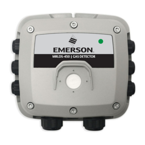
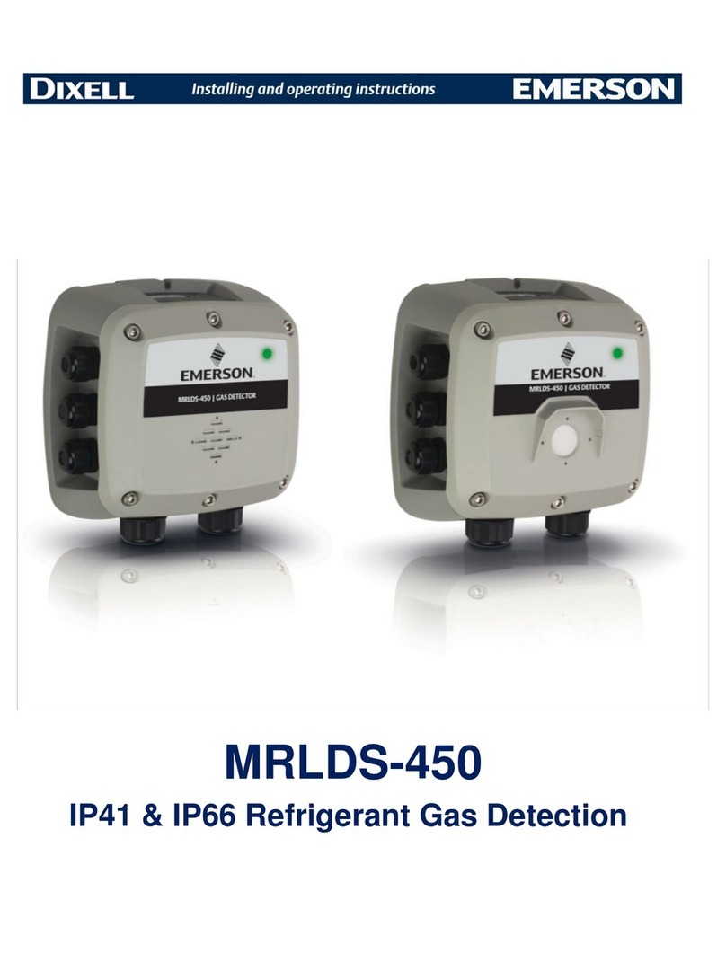
»The MRLDS-450 enclosure provides the following cable gland openings:
−2×, M20, supports 10-14mm cable outer diameter
−6×, M16, supports 4-8mm cable outer diameter
»Secondary circuit must be supplied from an isolating source.
»The wiring for the relays must be selected and fused according to the rated voltages,
currents, and environmental conditions.
»If stranded conductions are used, ferrule should be used.
»To comply with RFI immunity regulations, it is necessary to ground the shield of the
communications cable at the PLC, GDA controller, front-end controller or Building
Management System (For example, the chassis, the ground bus-bar, etc.).
3.2 Restrictions
The installation location must have appropriate supply power available for the instrument (For example, 19.5
to 28.5VDC or 24VAC). This ultimately determines the distance the instrument can be mounted from the
controller or power supply.
3.3 Mechanical Installation
3 Installation
CAUTION! The manufacturer of this product requires that a bump test or
calibration be performed following installation to verify instrument functionality.
WARNING! DO NOT allow the lid/sensor to hang from the ribbon cable. Failure to
comply may result in damage to the product.
1. Using the provided hardware, securely mount the MRLDS-450 Gas Detector according to the product
dimensions, maximum wiring lengths and following considerations:
a. Environment: the full range of environmental conditions when selecting a location.
b. Application: the specics of the application (possible leaks, air movement/draft, etc.) when
selecting a location.
c. Accessibility: the degree of accessibility required for maintenance purposes when selecting a
location.
d. Target Gas: the specic gravity of the target gas when selecting the height of the instrument.
2. Using a 5/32” (4mm) hex key/allen wrench (not included) remove the lid and disconnect the
ribbon cable from the base.
3. Set the lid and rubber gasket aside to be reinstalled later.
