manuals.online logo
Brands
  1. Home
  2. •
  3. Brands
  4. •
  5. Emerson
  6. •
  7. Gas Detector
  8. •
  9. Emerson Dixell XLH210 Wiring diagram

Emerson Dixell XLH210 Wiring diagram

1592039020 XLH210 GB r1.0 Gas Leak Detector 2016.04.26.doc XLH210 1/2
GAS LEAK DETECTOR
XLH210
1. GENERAL WARNINGS ......................................................................................................................1
2. GENERALDESCRIPTION..................................................................................................................1
3. INSTALLATION AND MOUNTING .....................................................................................................1
4. DIMENSIONS......................................................................................................................................1
5. GAS LEAK DETECTOR CONNECTIONS..........................................................................................1
6. XLH210 CONNECTIONS....................................................................................................................1
7. THE DISPLAY.....................................................................................................................................2
8. MEANING OF THE LABELS...............................................................................................................2
9. KIND OF SENSORS ...........................................................................................................................2
10. TECHNICAL DATA..............................................................................................................................2
11. DEFAULT SETTING VALUES............................................................................................................2
1. GENERAL WARNINGS
1.1 PLEASE READ BEFORE USING THIS MANUAL
•This manual ispart of the productand should be kept near the instrument for easy and quick reference.
•The instrument shall not be used for purposes different from those described hereunder. It cannot be
used as a safety device.
•Check the application limits before proceeding.
•Dixell Srl reserves the right to change the composition of its products, even without notice, ensuring the
same and unchanged functionality.
1.2 SAFETY PRECAUTIONS
•Check the supply voltage is correct before connecting the instrument.
•Do not expose to water or moisture: use the controller only within the operating limits avoiding sudden
temperature changes with high atmospheric humidity to prevent formation ofcondensation
•Warning:disconnect all electrical connections before any kind of maintenance.
•Fit the sensor where it isnot accessible bythe End User. The instrument mustnot be opened.
•In case of failure or faulty operation send the instrument back to the distributor or to “Dixell S.r.l.” (see
address) with a detailed description of the fault.
•Consider the maximum currentwhich can be applied to each relay(see Technical Data).
•Ensure that the wires for sensor, loads and the power supply are separated and far enough from each
other, without crossing or intertwining.
•In case of applications in industrial environments, the use of mains filters (our mod. FT1) in parallel with
inductive loads could be useful.
•This unit must be installed by a suitably qualified technician who will install this unit in accordance with
these instructions and the standards in their particular industry/country. Operator of the unit should be
aware of the regulations and standards in their industry/country for the operation of this unit. These notes
are only intended asa guide and the manufacturer bears no responsibility for the installation oroperation
of this unit.
2. GENERAL DESCRIPTION
The XLH210 is a microprocessor controller suitable for for 4÷20mA gas sensors.
The alarm thresholds can be set with display visualization and recognized through Pre-Alarm and Alarm relay.
It has an RS485 serial output with RTU Modbusprotocol to monitorremotely the XWEB monitoring system.
3. INSTALLATION AND MOUNTING
87 230
MAX37
210
130
120
MAX
28
HI
Fig. 1
3.1 WALL MOUNTING
1. Unscrew the 2 screws that keep connected the frontal and lower parts and separate the 2 parts
2. Unscrew the 4 frontal screws and remove the cover
3. Make the proper holes for cable-presses or pipe-presses using the centres signed in the bottom cover
(Fig. 1, H, I)
4. Make 3 holes in the wall, as indicated in Fig. 1 to fix the controller
5. Fix the cable-presses and the pipe-presses
6. Insert the wall-nugs, contained in the kit, into the holes made in the wall. Then use the o-rings and fix
the back partof the controllersby means of the 3 screws to the wall itself
7. Insert the wiring cablesin cable-presses or in the pipe-presses
8. Mount the frontal part using the previous 4 screws; do not press excessively in order to avoid plastic
deformation
9. After connecting the wiresto the terminal blocks close the cover (Fig.2, c) and fix itby the screws
4. DIMENSIONS
210 87
230
5. GAS LEAK DETECTOR CONNECTIONS
The instruments are provided with screw terminal block to connect cables with a cross section up to 2,5 mm2.
Heat-resistant cables have to be used. Before connecting cables make sure the power supply complies with the
instrument’s requirements. Separate the sensor cables from the power supply cables, outputs and the power
connections. Do not exceed the maximum current allowed on each relay, in case of heavier loads use a
suitable external relay.
5.1 GAS SENSOR CONNECTIONS
For the functioning of the sensor, please refer to the manual provided by the manufacturer.
6. XLH210 CONNECTIONS
6.1 RELAY AND BUZZER STATUS DURING THE ALARM
Note: this is the relay output situation with the parameter AS=oP.
STATUS
ALARM RELAY
OUTPUT
PRE-ALARM
RELAY OUTPUT
LABEL ON THE
DISPLAY
BUZZER
ON (no alarm)
22-23
29-30
ON
OFF
Pre-Alarm
30-31
PAL
INTERMITTENT
ALARM
21-22
ALL
CONTINUOS
OFF
OFF
OFF
Note: this is the relay output situation with the parameter AS=cL.
STATUS
ALARM RELAY
OUTPUT
PRE-ALARM
RELAY OUTPUT
LABEL ON THE
DISPLAY
BUZZER
ON (no alarm)
21-22
30-31
ON
OFF
Pre-Alarm
29-30
PAL
INTERMITTENT
ALARM
22-23
ALL
CONTINUOS
OFF
OFF
OFF
1592039020 XLH210 GB r1.0 Gas Leak Detector 2016.04.26.doc XLH210 2/2
7. THE DISPLAY
7.1 TO ENTER IN PARAMETER CONFIGURATION
1) Enter the “Pr1” level where the parameters are visible;press ” SET + DOWN “ for more than 3 seconds.
2) Enter the “Pr2” level; Select “Pr2” (PAS) with
n
key and press “ SET ”.
3) On the display will appear “0 - -” with a flashing zero.
4) Use
o
or
n
to input the security code in the flashing digit; confirmthe figure by pressing “ SET ”.
The security code is “321“.
7.2 TO CHANGE PARAMETER VALUES
1. Enter the Programming mode.
2. Select the required parameter.
3. Press the “ SET ” key to display its value (thatstart blinking).
4. Use
o
or
n
to change its value.
5. Press “ SET ” to store the new value and move to the following parameter.
To exit: Press ” SET and then UP “ or wait 15s without pressing a key.
NOTE: the new values are saved even if the Programming Mode will exitby time-out.
7.3 HOW TO LOCK / UNLOCK THE KEYBOARD
+
Keep the oand nkeyspressed together for more than 3s until appear:
-“POF”= keyboard is locked
-“Pon”= keyboard is unlocked
7.4 ON/OFF
By pushing the ON/OFF key, the instrument shows “OFF” for 5 sec. and the ON/OFF LED is
switched ON.
To put the instrument in ON mode press another time the key.
8. MEANING OF THE LABELS
Message
Meaning
on
The controller is on and it is working correctly
oFF (label or led)
The controller is OFF (stand-by);no leakages recognized.
PAL
The pre-Alarm is active (the AHL threshold has been reached)
ALL
The Alarm is active (the AHu threshold has been reached)
AHL
Value of the Pre-Alarm threshold (modifiable with SET button)
AHu
Value of the Alarm threshold (modifiable with SET button)
PoF
The keyboard islocked
Pon
The keyboard isunlocked
Err
SEnS
The gas sensor isnot connected or broken
The alarm message is displayed until the alarm condition recoveries. All the alarm messages are showed
alternating with the room temperature exceptfor the “P1” which is flashing. To reset the “EE” alarm and restart
the normal functioning pressany key, the “rSt” message is displayed for about 3s.
9. KIND OF SENSORS
GAS: any model with 4÷20mA signal;maximum consumption not greater than 4V/A.
Note:
•The sensorscan be provided by Dixell with a differentP/N (the P/N depend on the gas type).Please
check with our sales department.
The sensorscan recognize the following gas: R134A, R410A, R407C, R404A, R507A, R407A, R407F
R744, R290.
The sensor can be IP41 or IP66. Please check with our sales department.
•There is a 5-minute power-up delay to allow the sensor to stabilise.
The green LED will flash at 1 second intervals during the warm-up.
•In an alarm condition:
ogreen LED stays on and the red LED is on
oaudible alarm operates(if not disabled and after delay, ifset).
orelay output activates (after a delay, if set)
oI output changes proportionally with gas concentration.
In a faultcondition:
ogreen LED will be offand the red LED will be on
ocurrent fault output will activate:2mA on the 4-20mA output
10. TECHNICAL DATA
Housing: self extinguishing ABS
Case: frontal 210x230 mm; depth 87mm
Mounting: See par. 3
Protection: IP65
Connections: Screw terminal block ≤2,5mm2wiring
Power supply: 230Vac 50/60Hz ±10%
Power absorption: 7VA max
Display:3 digits,red LED; 3 digits,yellow LED low
Inputs: 4÷20mA input
Digital inputs: door switch, free voltage
Relay outputs: Alarm (oA2): 16A 250V
Light (oA1): 16A 250Vac
Pre-Alarm (0A4): 8A 250Vac
Other outputs: Buzzer (Standard)
Direct RS485 (optional)
Data storing: on the non-volatile memory (EEPROM)
Kind of action: 1B
Pollution grade: normal
Software class: A
Operating temperature: 0÷60°C
Storage temperature: -25÷60°C
Relative humidity: 20÷85% (no condensing)
Resolution: 1% or 0.1% (selectable)
11. DEFAULT SETTING VALUES
Label
Description
Range
Value
Menù
rEH
Resolution for gas sensor
in ÷ Hd
Hd
Pr2
tib
Timeout inhibition buzzer
0 ÷ 250 min
3
Pr1
AHL
Threshold gas pre-alarm
0% ÷ AHu
50.0
Pr1
AHu
Threshold gas alarm
AHL ÷ 100%
80.0
Pr1
AHH
Gas alarm recovery differential
0.5 ÷ 25 %
10.0
Pr1
AHd
Gas alarm delay
0 ÷ 250 min
0
Pr1
dHo
Delay of gas alarm at start-up
0.0 ÷ 23.5 hours
0.0.
Pr1
o3
Gas sensor calibration
-10 ÷ 10 %
0.0
Pr2
P3P
Gas sensor presence
n = not present; Y = present
Y
Pr2
Lci
Readout with 4 mA
-999% ÷ uci
0
Pr2
uci
Readout with 20 mA
LCi ÷ 999%
100
Pr2
i2P
Door switch digital input polarity
cL =open / oP = close
oP
Pr1
AS
Alarm relay polarity
cL =open / oP = close
oP
Pr1
Adr
RS485 serial address
1÷247
1
Pr1
Ptb
Parameter table
read only
-
Pr2
rEL
Software release
read only
-
Pr1
Pr2
Access to the protected parameter list
-
321
Pr1
Display with the
status of the
controller (see
section 8)
Value (%)
measured by the
sensor; within the
values between
the parameters
“Lci” and “uci”

Other Emerson Gas Detector manuals

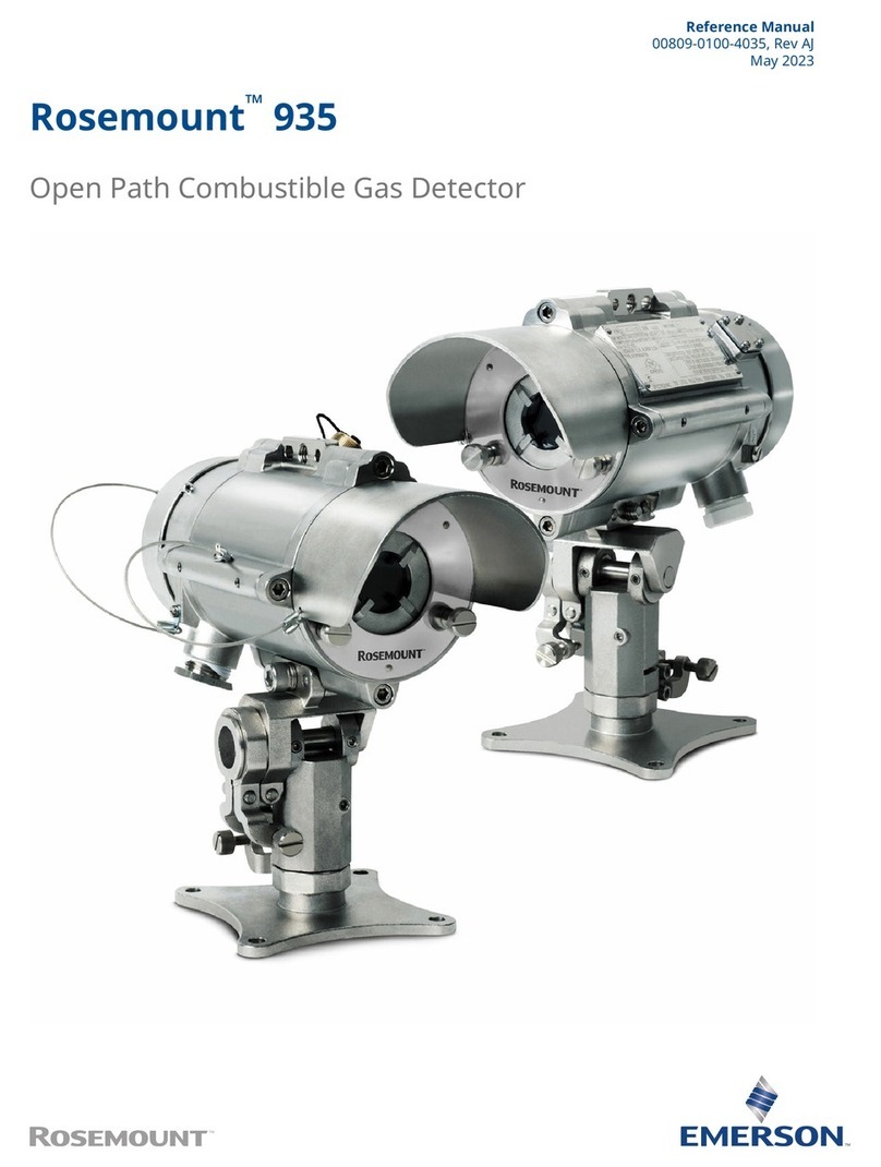
Emerson Hart Rosemount 935 User manual

Emerson

Emerson Hart Rosemount 935 User manual

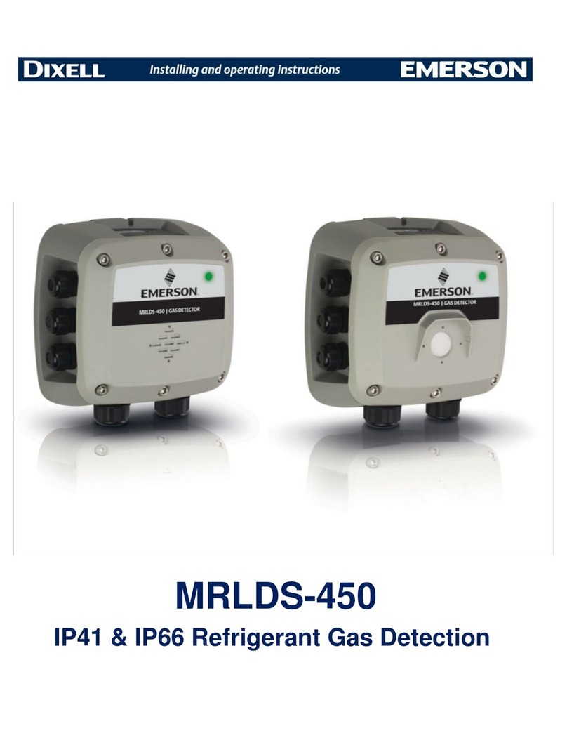
Emerson MRLDS 450 User manual

Emerson

Emerson MRLDS 450 User manual

Emerson Rosemount 936 User manual

Emerson

Emerson Rosemount 936 User manual

Emerson Rosemount 935 User manual

Emerson

Emerson Rosemount 935 User manual

Emerson Rosemount 935 User manual

Emerson

Emerson Rosemount 935 User manual

Emerson Rosemount 928 User manual

Emerson

Emerson Rosemount 928 User manual

Emerson MRLDS-450 User manual

Emerson

Emerson MRLDS-450 User manual

Emerson MRLDS-450 Wiring diagram

Emerson

Emerson MRLDS-450 Wiring diagram

Emerson Rosemount 928 User manual

Emerson

Emerson Rosemount 928 User manual

Emerson MRLDS-450 User manual

Emerson

Emerson MRLDS-450 User manual

Emerson GDU-Incus User manual

Emerson

Emerson GDU-Incus User manual

Emerson Rosemount 936 User manual

Emerson

Emerson Rosemount 936 User manual

Emerson Rosemount 935 User manual

Emerson

Emerson Rosemount 935 User manual

Emerson MRLDS-450 User manual

Emerson

Emerson MRLDS-450 User manual

Emerson Rosemount 936 User manual

Emerson

Emerson Rosemount 936 User manual

Emerson Rosemount 925FGD User manual

Emerson

Emerson Rosemount 925FGD User manual

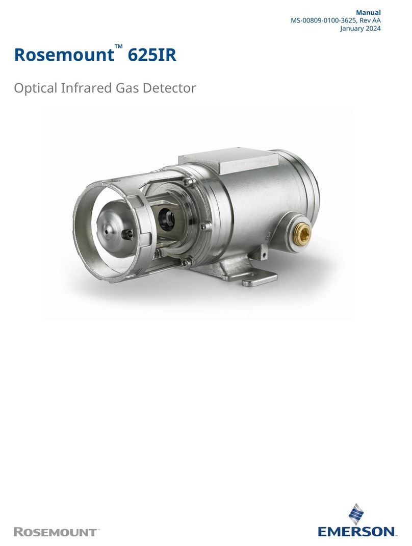
Emerson Rosemount 625IR User manual

Emerson

Emerson Rosemount 625IR User manual

Emerson GDU-Incus User manual

Emerson

Emerson GDU-Incus User manual

Emerson Rosemount 925FGD User manual

Emerson

Emerson Rosemount 925FGD User manual

Emerson MRLDS-450 User manual

Emerson

Emerson MRLDS-450 User manual

Emerson Rosemount 935 User manual

Emerson

Emerson Rosemount 935 User manual

Emerson MRLDS-450 User manual

Emerson

Emerson MRLDS-450 User manual

Emerson Net Safety MLP-A-SC1100 User manual

Emerson

Emerson Net Safety MLP-A-SC1100 User manual

Emerson Rosemount 935 User manual

Emerson

Emerson Rosemount 935 User manual

Popular Gas Detector manuals by other brands

Trotec BG30 operating manual

Trotec

Trotec BG30 operating manual

Wizmart NB-983 Series user manual

Wizmart

Wizmart NB-983 Series user manual

Riken Keiki SD-1DOX-AS operating manual

Riken Keiki

Riken Keiki SD-1DOX-AS operating manual

AKO AKOGAS AKO-576410 instructions

AKO

AKO AKOGAS AKO-576410 instructions

Honeywell BW Clip Real Time Quick reference guide

Honeywell

Honeywell BW Clip Real Time Quick reference guide

GMI PPM Gasurveyor 500 User handbook

GMI

GMI PPM Gasurveyor 500 User handbook

Dectris EIGER 2 X 9M-V Technical specifications

Dectris

Dectris EIGER 2 X 9M-V Technical specifications

Critical Environment Technologies LPT Series Operation manual

Critical Environment Technologies

Critical Environment Technologies LPT Series Operation manual

Medem AGDS-V installation instructions

Medem

Medem AGDS-V installation instructions

Quatrosense Environmental QEL Installation, operation and maintenance manual

Quatrosense Environmental

Quatrosense Environmental QEL Installation, operation and maintenance manual

Riken Keiki GX-2009 user guide

Riken Keiki

Riken Keiki GX-2009 user guide

Emos GS869 manual

Emos

Emos GS869 manual

Evikon PluraSens E2608 Series user manual

Evikon

Evikon PluraSens E2608 Series user manual

Teledyne OLCT 60 user manual

Teledyne

Teledyne OLCT 60 user manual

Honeywell BW Ultra user manual

Honeywell

Honeywell BW Ultra user manual

Gemini 911 Installation and use manual

Gemini

Gemini 911 Installation and use manual

Amos 550 instruction manual

Amos

Amos 550 instruction manual

JB LDC-4000 operating manual

JB

JB LDC-4000 operating manual

manuals.online logo
manuals.online logoBrands
  • About & Mission
  • Contact us
  • Privacy Policy
  • Terms and Conditions

Copyright 2025 Manuals.Online. All Rights Reserved.