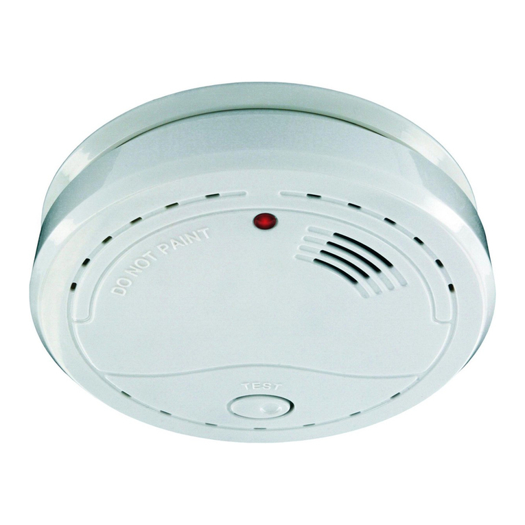
Oldham OLC 10 User manual

1
User Manual
OLC 10
OLCT 10
Analog Gas Detector
Non ATEX version
Part Number : NPO10GB-NEX
Revision : ZZ.1

2
User Manuals in others language are available on Website
https://teledynegasandflamedetection.com
Copyright ©December 2019 by OLDHAM SIMTRONICS S.A.S.
All rights reserved. No reproduction of all or part of this document, in any form, is permitted without
the written consent of Oldham Simtronics S.A.S.
All of the information that is provided in this document is accurate to the best of our knowledge.
As a result of continuous research and development, the specifications of this product may be changed
without prior notice.
Oldham Simtronics S.A.S.
Rue Orfila
C.S. 20417
F –62027 ARRAS

3
TABLE OF CONTENTS
I. PRESENTATION OF DIFFERENT VERSIONS.................................................................3
Different versions available..........................................................................................................3
II. MECHANICAL INSTALLATION OF DIFFERENT VERSIONS, DIMENSIONS AND
MOUNTING .............................................................................................................................3
III. ELECTRICAL INSTALLATION OF DIFFERENT VERSIONS......................................5
1. Connection of OLC 10, OLCT 10 EXPLO or OLCT 10 SC (Semi-Conductor) to a
controller for combustible gas detection:...............................................................................5
2. Connection of two OLC 10 TWIN to a controller.................................................................6
3. Connection of two OLCT 10 TOX (maximum 5) to a controller for detection of the same
toxic gas.................................................................................................................................7
4. Connection of two OLCT 10 TOX networks (5 detectors max. per network) for detection
of two different toxic gases or monitoring of two conjoined areas to a two-channel
controller................................................................................................................................8
IV. MAINTENANCE......................................................................................................................9
1. Periodic maintenance with an OLC 10 detector (comb. gas) ................................................9
2. Periodic maintenance with an OLC 10 TWIN transmitter (comb. gas) ................................9
3. Periodic maintenance with an OLCT 10 transmitter (comb. or toxic gas)............................9
4. Periodic maintenance with several OLCT 10 transmitters for toxic gas .............................11
5. Sensor replacement..............................................................................................................11
V. TECHNICAL SPECIFICATIONS.......................................................................................13
1. TECHNICAL SPECIFICATIONS - OLC 10 / OLC 10 Twin............................................13
2. TECHNICAL SPECIFICATIONS - OLCT 10 Explo Transmitter.....................................14
3. TECHNICAL SPECIFICATIONS - OLCT 10 CO Transmitter.........................................15
4. TECHNICAL SPECIFICATIONS - OLCT 10 SC Transmitter..........................................16
5. TECHNICAL SPECIFICATIONS - OLCT 10 NO Transmitter.........................................17
6. TECHNICAL SPECIFICATIONS - OLCT 10 NO2 Transmitter.......................................18
VI. DETAIL SPECIFICATIONS FOR USE..............................................................................19
1. Special precautions ........................................................................................................19
2. Reactions to other combustible gases............................................................................19
VII. DECLARATIONS OF CONFORMITY..............................................................................21

0
Limitation of Liability
The Company OLDHAM SIMTRONICS S.A.S., hereinafter referred to as “OLDHAM SIMTRONICS”
throughout this document, shall not be held responsible for any damage to the equipment or for any
physical injury or death resulting in whole or in part from the inappropriate use or installation of the
equipment, non-compliance with any and all instructions, warnings, standards and/or regulations in force.
No business, person or legal entity may assume responsibility on behalf of OLDHAM SIMTRONICS,
even though they may be involved in the sale of OLDHAM SIMTRONICS products.
OLDHAM SIMTRONICS shall not be responsible for any direct or indirect damage, or any direct or
indirect consequence, resulting from the sale and use of any of its products UNLESS SUCH
PRODUCTS HAVE BEEN SELECTED BY OLDHAM SIMTRONICS ACCORDING TO THE
APPLICATION.
Ownership clauses
The drawings, specifications, and information herein contain confidential information that is the property
of OLDHAM SIMTRONICS.
This information shall not, either in whole or in part, by physical, electronic, or any other means
whatsoever, be reproduced, copied, divulged, translated, or used as the basis for the manufacture or sale
of OLDHAM SIMTRONICS equipment, or for any other reason without the prior consent of
OLDHAM SIMTRONICS.
Warning
This is not a contractual document. In the best interest of its customers and with the aim of improving
performance, OLDHAM SIMTRONICS reserves the right to alter the technical features of its equipment
without prior notice.
READ THESE INSTRUCTIONS CAREFULLY BEFORE THE FIRST USAGE: these instructions
should be read by all persons who have or will have responsibility for the use, maintenance, or repair of
the instrument.
This instrument shall only be deemed to be in conformance with the published performance if used,
maintained, and repaired in accordance with the instructions of OLDHAM SIMTRONICS by OLDHAM
SIMTRONICS personnel or by personnel authorized by OLDHAM SIMTRONICS.
Important Information
The modification of the material and the use of parts of an unspecified origin shall entail the cancellation
of any form of warranty.
The use of the unit has been projected for the applications specified in the technical characteristics.
Exceeding the indicated values cannot in any case be authorized.
OLDHAM SIMTRONICS recommends regular testing of fixed gas detection installations (read Chapter
IV).
Before any intervention on the detector, please refer to the EN 60079-29-2 standard.
Warranty
Under normal conditions of use and on return to the factory, OLC/OLCT10 detectors carry a 2-year
warranty excluding accessories such as sensors, filters, etc.
1
Destruction of the equipment
European Union (and EEA) only. This symbol indicates that, in conformity with directive DEEE
(2002/96/CE) and according to local regulations, this product may not be discarded together with
household waste.
It must be disposed of in a collection area that is set aside for this purpose, for example at a site that
is officially designated for the recycling of electrical and electronic equipment (EEE) or a point of exchange
for authorized products in the event of the acquisition of a new product of the same type as before.

2

3
I. PRESENTATION OF DIFFERENT VERSIONS
The OLC 10, OLC 10 TWIN and OLCT 10 EXPLO combustible gas detectors are detectors fitted with catalytic
sensors and intended for use in boiler rooms and parking lots.
The OLCT 10 TOX gas detectors are 4-20mA transmitters equipped with electrochemical sensors and especially
designed to detect toxic gases in commercial and light industrial applications (parking lots, boiler room, etc).
Different versions available
-OLC 10: combustible gas
-OLC 10 TWIN: combustible gas
-OLCT 10 EXPLO: combustible gas (transmitter version, 4-20 mA output)
-OLCT 10 TOX: toxic gas (transmitter version, 4-20 mA output)
II. MECHANICAL INSTALLATION OF DIFFERENT
VERSIONS, DIMENSIONS AND MOUNTING
The OLC/OLCT 10 gas detectors-transmitters are mounted vertically with the cable entries positioned downwards.
Drill two holes 104 mm apart on the base to mount the units.
104 mm

4

5
III.ELECTRICAL INSTALLATION OF DIFFERENT
VERSIONS
1. Connection of OLC 10, OLCT 10 EXPLO or OLCT 10 SC (Semi-
Conductor) to a controller for combustible gas detection:
Notes: - The controller configuration will be different based upon the use of an OLC 10 or OLCT 10
- Cable to be used: 3 conductors, 3x1 mm² LiYCY type
1
2
3
1 2 3
e.g., CONTROLLER MX 15
Connect the 3 wires based on the
corresponding numbering on the
sensor.
Connect the 3 wires based on the
corresponding numbering on the
controller.
1= signal*
2= -
3= +
1
2
3
OLC 10
OLCT 10
EXPLO
*analog signal 4-20 mA (I out) on OLCT 10.

6
2. Connection of two OLC 10 TWIN to a controller
Cable to be used: 3 and 4 core cable, 3x1 mm² and 4x1 mm² LiYCY type
Connect the 3 wires based on the
corresponding numbering on the
controller.
Connect the 3wires based on the
corresponding numbering on the
first sensor.
Connect the 4wires based on the
corresponding numbering on the
previous and the following sensor.
1
2
3
1= signal
2= -
3= +
IN
4 3 2 1
MX 15 CONTROLLER
OUT
4 3 2 1
IN
OUT
4 3 2 1
4 3 2 1
1 2 3
2
1
3

7
3. Connection of two OLCT 10 TOX (maximum 5) to a controller
for detection of the same toxic gas
Cable to be used: One pair (0.75 mm²) screened cable
Note: the free terminals allow the connection of another network of OLCT 10 TOX.
COMMENTS:
-the number of OLCT 10 toxic gas detectors shall be configured on the controller,
-the signal read by the controller is the average of the “n”detectors. As a result, a signal fault may not be
detected.
In the event that 2 networks are used, it is cost-effective to use a single cable (2 pairs) subject to compliance with
wiring as follows:
IN
1 2 3
IN OUT
CONTROLLER MX15 for example
1 3
3 1 3 1 3 1 3 1
Connect the 2wires based on the
corresponding numbering on the
first sensor.
Connect the 2wires based on the
corresponding numbering on the following
sensor.
Connect the 2wires based on the
corresponding numbering on the
controller.
1
3
1
3
1
3
1= Iout
3= +Vdc
OLCT 10 TOX
3 1 3 1

8
4. Connection of two OLCT 10 TOX networks (5 detectors max.
per network) for detection of two different toxic gases or
monitoring of two conjoined areas to a two-channel controller
Cable to be used: Two pairscreened cable (0.75 mm²)
Controller with 2 channels at minimum
Information for this example:
-channel 1 is a channel connected to two sensors for detection of CO
-channel 2 is a channel connected to two sensors for detection of NO
-detector 1 (CO) also acts as junction box for detector 2 (NO)
-detector 2 (NO) also acts as junction box for detector 3 (CO)
-detector 3 (CO) also acts as junction box for detector 4 (NO)
Example: one zone, 2 gases
Detector 1
Detector 2
Detector 3
Detector 4
Cable with 4
wires
Channel 1
Channel 2
MX 32
controller

9
IV. MAINTENANCE
Caution: The actions described in this paragraph are intended for authorized and trained individuals who are
likely to question the detection safety.
Gas detection instruments are potential life-saving devices. Recognizing this fact, OLDHAM SIMTRONICS
recommends that a functional “bump” test be performed on every fixed gas-monitoring instrument as part of a regular
maintenance program. A functional test is defined as a brief exposure of the detector to a concentration of gas(es) in
excess of the lowest alarm set-point for each sensor for the purpose of verifying sensor and alarm operation and is not
intended to be a measure of the accuracy of the instrument.
Bump test frequency depends on application, field conditions, exposure to gas, sensor technology, and environmental
conditions. For new installations it may be prudent to carry out bump tests frequently at first, increasing the time
intervals as confidence grows with experience in the installation concerned, on the basis of the maintenance record. The
maintenance test interval should not be more than 3 months.
If an instrument fails to operate properly during any functional “bump” test, a full instrument calibration should be
performed successfully prior to use. Calibration frequency will be based on bump tests results. However it cannot be
more than 12 months.
These recommendations are based on safe work procedures, industry best practises, and regulatory standards to ensure
worker safety. OLDHAM SIMTRONICS is not responsible for setting safety practices and policies.
1. Periodic maintenance with an OLC 10 detector (comb. gas)
-The “maintenance”position was selected on the controller in order to disable its relays (see manual of relevant
product)
Reminder: make sure the detector is in clean air - otherwise inject zero air on the detector (with calibration kit)
with a flow rate of 60 l/h, then wait for the stabilisation of measurement
-Perform the zero setting of the controller (see manual of relevant product)
-Now inject the calibration gas (flow rate 60l/h) into the OLC 10 sensor and wait for signal stabilisation on the
controller display
-If necessary, calibrate the sensitivity using the “S”potentiometer of the controller (see manual of relevant
product)
-Upon completion of calibration: wait for the “return to zero”on the controller display
-Return to the “normal”mode of the controller (see manual of relevant product)
2. Periodic maintenance with an OLC 10 TWIN transmitter (comb.
gas)
-The procedure is almost identical to point 1 (OLC 10), with the exception of sensitivity adjustment which is
performed on the OLC 10 TWIN detector that is less sensitive.
-To determine the least sensitive detector, inject gas on the two detectors, one after the other (wait for the signal
to read zero). The detector that gives the lowest measurement is the less sensitive.
3. Periodic maintenance with an OLCT 10 transmitter (comb. or
toxic gas)
-It is required that the kit provided by OLDHAM SIMTRONICS be used (P/N 6147872)
-Remove the end-cap that provides access to settings, located on the right side of the sensor
-Connect this kit on the male plug of the circuit, as indicated below:

10
-Toggle the changer-over (under the connector) on «CAL» position (to the right)
Caution: after 9 minutes the transmitter automatically returns to normal operation! (only version OLCT
10 explo)
Reminder: make sure the detector is in clean air - otherwise inject zero air or nitrogen on the sensor at a flow
rate of 60 l/h –and wait for the stabilisation of the measurement given by the voltmeter.
-Set the ZERO using the zero potentiometer to read 0 mV on the voltmeter
-Now inject the calibration gas (60l/h), wait for the signal stabilisation on the voltmeter
-If required, set the sensitivity using the “S”potentiometer to read 1,600mV for the full scale (corresponding to
20mA)
-Note: if you use a gas concentration lower than 100% of the scale, calculate (rule of three) and adjust to obtain
the corresponding value (from 0 to 1600 mV)
-Stop calibration gas injection (remove the calibration cup)
-Wait for the “return to zero”on the voltmeter
-Again toggle the changer-over to the normal position (to the left)
MAINTENANCE CONNECTOR WIRES:
- +VDC/red = + power supply
- - 4-20 mA/blue = - of voltage, image of 4-20mA
-+ 4-20 mA/green = + of voltage, image of 4-20mA
- S Signal /yellow = signal from 0mV to 1600mV for zero and sensitivity setting
- Ref 2.5 V/gray = zero reference for reading of signal from 0mV to 1600mV
- GND/black = electronic circuit ground.
ZERO (4mA) potentiometer SENSITIVITY (20mA) potentiometer
S Signal
+VDC
+4-20 mA
- 4-20 mA
Ref 2.5V
GND
V
voltmeter
CHANGER-OVER
Voltmeter
Read on the voltmeter 400mV for 4mA and 2000mV for 20mA

11
Notes regarding the OLCT 10 version for combustible gases:
-the transmitter controls an “ambiguity resolution”function: if the sensor detects a gas concentration over
100% LEL (20 mA), it will be locked on a signal of 23.2 mA acknowledgeable through power supply shut-off
or toggling of maintenance switch. The ambiguity resolution may be automatically acknowledged if the PPS3
points are short-circuited.
-Upon switching on, the output signal is set to 2mA during the 60-second stabilisation time.
4. Periodic maintenance with several OLCT 10 transmitters for
toxic gas
Use the procedure described in the previous paragraph. However:
-Start with the last transmitter in the loop in relation to the controller
-Calibrate each transmitter in the loop and end with the first
5. Sensor replacement
Sensor has to be replaced as a result of impracticable calibration or as a preventive measure.
Perform a new calibration after a sensor replacement.
PPS3

12

13
V. TECHNICAL SPECIFICATIONS
1. TECHNICAL SPECIFICATIONS - OLC 10 / OLC 10 Twin
Combustible gas detector
Detection principle: Catalytic
Range: 0-100% LEL methane, propane or butane.
Output signal: Wheatstone bridge circuit
Power supply: Current through Oldham Simtronics MX controllers
Connections: OLC 10 Version:
- 3-wire terminal block, maximum distance 300 m in 1.5 mm² with
MX 15 controller
- 1 cable gland M16: cable diameter 4 to 8 mm
OLC 10 Twin Version (two sensors on channel input MX 15)
- 1 3-wire terminal block to the controller
- 1 4-wire terminal block to the second sensor
- maximum total distance 300 m in 1.5 mm² with MX 15 controller
- 2 cable glands M16: cable diameter 4 to 8 mm
Dimensions: Width 118 mm, Height 157 mm, Depth 60 mm
Material: Plastic
Protection: IP65
Storage: 6 months safe from air 0°C<T<20°C +10%<RH<60%
Estimated lifetime: > 36 months
Temperature range: -10°C to + 45°C
Humidity range: 0% RH to 95% RH
Pressure range: 1 bar ± 20%
Linearity deviation: from 0 and 70% LEL: 1% LEL CH4
from 70 and 100% LEL: 7% LEL CH4
Long-term drift Zero < 10% LEL/year
under normal operating Sensitivity < 20 % of the measured value/year
conditions:
Humidity impact: ± 5 % of relative sensitivity
(10 to 90% RH) at 40°C
Response time: T50 <10 sec, T90<20 sec
Certification: Electromagnetic Compatibility EN 50270 :2015 (type2)

14
2. TECHNICAL SPECIFICATIONS - OLCT 10 Explo Transmitter
Combustible gas transmitter
Detection principle: Catalytic
Range: 0-100% LEL methane, propane or butane.
Signal output: 4 –20 mA, default 0.5 mA or 23.2 mA
Ambiguity resolution: signal sets at 23.2 mA if measurement 100% LEL
Acquit by power cycling the transmitter
Ambiguity resolution may be deleted through point of programming
Settings: Local through Zero and Sensitivity potentiometers
Position Maintenance 2 mA
6-pin connector for gas measuring and current image
(100-ohm shunt)
Power supply: 15 to 30 V dc
Consumption: maximum 100 mA
Cable length: according to the controller
Load resistance: 300 ohms
Connection: 3-wire terminal block, 2 wires for power supply, 1 wire for signal
1 cable gland M16: cable diameter 4 to 8 mm
Dimensions: Width 118 mm, Height 157 mm, Depth 60 mm
Material: Plastic
Protection: IP65
Storage: 0°C<T<30°C
Estimated lifetime: > 36 months
Temperature range: -10 to + 4°C
Humidity range: 0% RH to 95% RH
Pressure range: 1 bar ± 20%
Linearity deviation: from 0 and 70% LEL: 1% LEL CH4
from 70 and 100% LEL: 7% LEL CH4
Temperature drift: < 5% LEL Methane or < 20% of indication
(-10°C + 40°C)
Long-term drift under Zero point < 10% LEL methane
normal operating conditions: Sensitivity < 20% of measured value/year
Humidity impact: ± 5% of relative sensitivity
(10 to 90% RH) at 40°C
Response time: T50 <10 sec, T90<20 sec
Certification: Electromagnetic Compatibility EN 50270 :2015 (type2)

15
3. TECHNICAL SPECIFICATIONS - OLCT 10 CO Transmitter
Detection principle: Electrochemical sensor
Range: 0-300 ppm CO
Signal output: 4 –20 mA
Settings: Local through Zero and Sensitivity potentiometers
Position Maintenance 2 mA
6-pin connector for gas measuring and current image
(100-ohm shunt)
Power supply: 15 to 30 VDC
Consumption: maximum 30 mA
Cable length: according to the controller
Connection: 1 terminal block with 2 input wires, 1 terminal block with 2 output wires
If cable with a gas signal pair: 1 terminal block with 2 input wires
with copy on 1 terminal with 2 wires
2 cable gland M16: cable diameter 4 to 8 mm
Dimensions: Width 118 mm, Height 157 mm, Depth 60 mm
Material: Plastic
Protection: IP65
Storage: 6 months safe from air 0°C<T<20°C +10%<RH<60%
Estimated lifetime: > 24 months
Temperature range: -10 to + 45°C
Humidity range: 15% RH to 90% RH
Pressure range: 1 bar ± 20%
Linearity deviation: 0 - 100 ppm ± 3 ppm
100 –1,000 ppm ± 4% relative
Temperature drift: < 5 ppm or < 5 % of the indication
(-10°C + 40°C)
Long-term drift under
normal operating conditions: Sensitivity: < 10% of measured value/year
Response time: T50 <15 sec, T90<30 sec
Certification: Electromagnetic Compatibility EN 50270 :2015 (type2)

16
4. TECHNICAL SPECIFICATIONS - OLCT 10 SC Transmitter
Detection principle: semi-conductor sensor
Range: 0-2000 ppm R134A, R22
Signal output: 4 –20 mA
Settings: Local through Zero and Sensitivity potentiometers
Position Maintenance 2 mA
4-pin connector for gas measuring and current image
(100-ohm shunt)
Power supply: 15 to 30 VDC
Consumption: maximum 100 mA
Cable length: according to the controller
Connection: 3-wire terminal block, 2 wires for power supply, 1 wire for signal
1 cable gland M16: cable diameter 4 to 8 mm
Dimensions: Width 118 mm, Height 157 mm, Depth 60 mm
Material: Plastic
Protection: IP65
Storage: 6 months safe from air 0°C<T<30°C
Estimated lifetime: > 24 months
Temperature range: -10 to + 60°C
Humidity range: 20% RH to 90% RH
Pressure range: 1 bar ± 10%
Linearity deviation: 0 - 10 ppm ± 0.3 ppm
10 –30 ppm ± 5% relative
Temperature drift: < 0.4 ppm or < 20 % of the indication
(-10°C + 40°C)
Long-term drift under
normal operating conditions: Sensitivity: < 20% of measured value/year
Response time: T50< 51s (R22)
T50 <30 sec, (R134a)
Minimum sensitivity threshold 10 ppm
Maximum sensitivity threshold 5000 ppm during 90s without sensitivity loss
Recommended Alarm Threshold 200 ppm
Minimum time to detect the lowest concentration less than 25s after injection of 500 ppm R134A
Recovery time less than 160s after injection of 8 min of 1000 ppm R134A
Certification: Electromagnetic Compatibility EN 50270:2015 (type2)
In accordance with EN 14624 certification
Other manuals for OLC 10
1
This manual suits for next models
1
Table of contents
Other Oldham Gas Detector manuals

Oldham
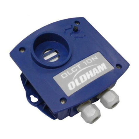
Oldham OLCT 10N User manual

Oldham
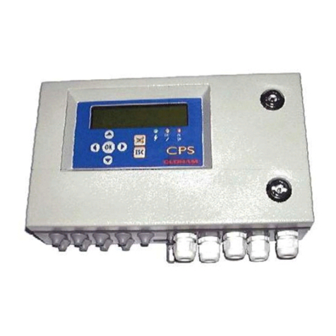
Oldham CPS Series User manual

Oldham
Oldham ctx 300 User manual

Oldham
Oldham OLC 10 User manual

Oldham
Oldham Surveyor 4B Installation guide

Oldham
Oldham MX62 User manual

Oldham
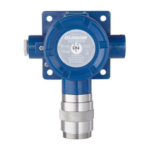
Oldham OLC 100 User manual

Oldham
Oldham SV 4B User manual

Oldham
Oldham CTX 300 CO2 User manual

Oldham
Oldham MX62 User manual