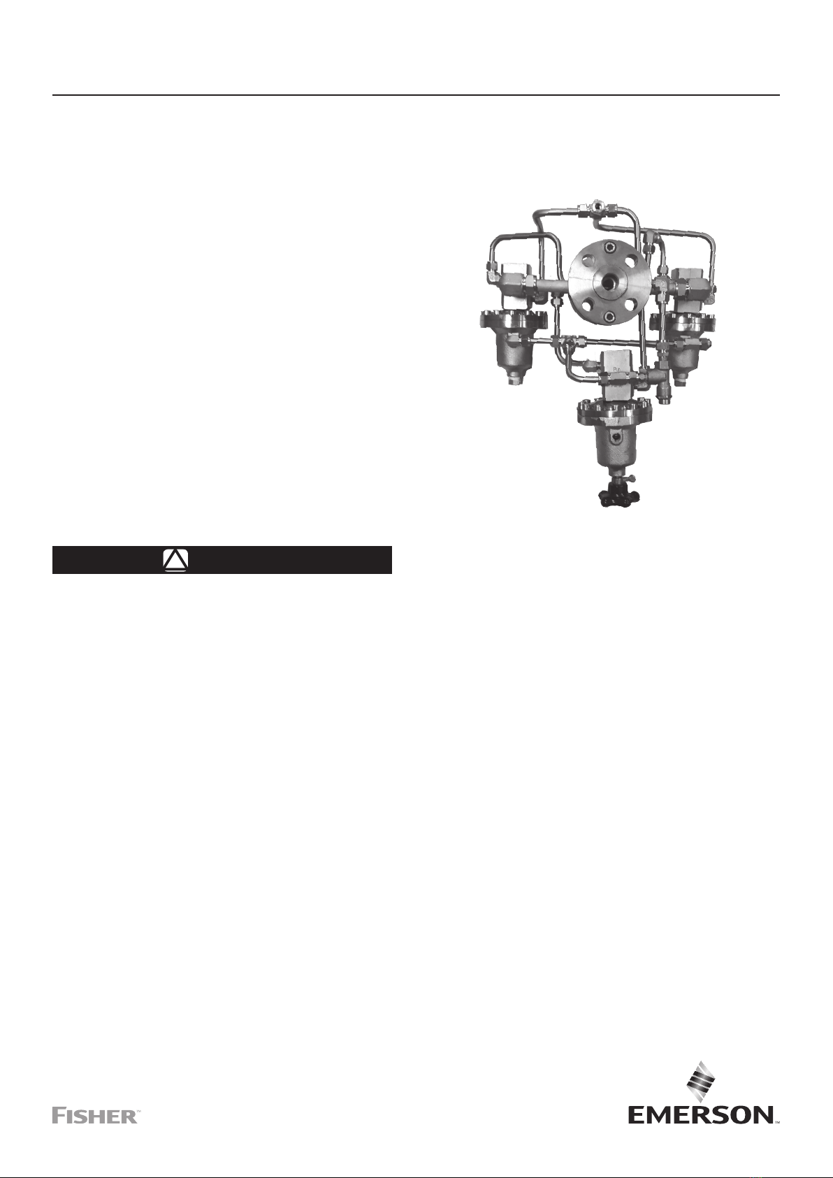
Emerson Fisher 114PL User manual

Type 114PL
Instruction Manual
D104438X012
March 2019
Type 114PL High-Pressure Reducing and
Low-Flow System
Table of Contents
Introduction..................................................................1
Specifications .............................................................. 2
Principle of Operation.................................................. 2
Installation ...................................................................2
Startup and Adjustment ............................................... 4
Maintenance................................................................4
Parts Ordering ............................................................. 4
WARNING
!
Failure to follow these instructions or
to properly install and maintain this
equipment could result in an explosion
and/or fire causing property damage and
personal injury or death.
Fisher™ regulators must be installed,
operated and maintained in accordance
with federal, state and local codes, rules
and regulations and Emerson Process
Management Regulator Technologies,
Inc. instructions.
If the regulator vents gas or a leak
develops in the system, service to
the unit may be required. Failure
to correct trouble could result in a
hazardous condition.
Call a gas service person to service the
unit. Only a qualified person must install
or service the regulator.
Introduction
Scope of the Manual
This manual provides instructions for installation,
startup, adjustment and maintenance for Type 114PL
Pressure Reducing System. For pilots maintenance,
instructions and parts list, see Type BSL85 Instruction
Manual D103711X012.
Product Description
Type 114PL
Type 114PL high-pressure reducing and low-flow
system is a battery of three Type BSL85 pilots (see
Instruction Manual, D103711X012) where two of them
are pneumatically loaded and the third one is spring-
loaded. It is designed for high-pressure reduction with
low-flow conditions.
Type RPE (Electric Heater)
Type RPE can be used together with the Type 114PL.
Type RPE is used for reheating gas supplying
pressure reducing regulator pilots. Type RPE avoids
the inconveniences caused by freezing which
occur during large pressure drops. (See Instruction
Manual, D103694X012).
Figure 1. Type 114PL
Europe, Middle East and Africa Only

Type 114PL
2
Specifications
The Specifications section lists the specifications for Type 114PL Pressure Reducing System. Factory specification
are stamped on the nameplate fastened on the regulator at the factory.
Body Sizes and End Connection Styles
DN 25 / 1 NPS - CL600 Flanged
Outlet Pressure Range (Pd)(1)
1.0 to 60 bar / 14.5 to 870 psig
See Table 1
Maximum Allowable Operating Pressure (Ps)(1)
100 bar / 1450 psig
Maximum Obtainable Operating Pressure (Pu)(1)(2)
85 bar / 1233 psig
Construction Materials
Pilot Body: Steel
Pilot Manometric Box BMP (spring case): Steel
Pilot Manometric Box BMP (cover): Steel
Flange and spacer: Steel
Option
RPE (Electric Heater)
1. The pressure/temperature limits in this Instruction Manual or any applicable standard limitation should not be exceeded.
2. In extreme conditions (isopropanol, methanol)
Principle of Operation
Type 114PL high-pressure reducing and low-flow
system uses inlet pressure as the operating medium,
which is reduced through the spring-loaded pilot to
load the pneumatic-loaded pilots’ cases.
When the outlet pressure (Pd) drops, the motorization
pressure (Pm) opens more the nozzles in the
pneumatic-loaded pilots supplying the required flow to
the downstream system.
Any excess motorization pressure on the actuator
diaphragm escapes downstream through the bleed
restriction in the pilot.
When the gas demand in the downstream system has
been satisfied, the outlet pressure (Pd) increases. In
this case, the outlet pressure closes the nozzles in the
pneumatic-loaded pilots until reach the setting value.
Installation
WARNING
!
Personal injury or equipment damage,
due to bursting of pressure-containing
parts may result if this system is
overpressured or is installed where
service conditions could exceed the
limits given in the characteristics
section and on the appropriate
nameplate or where conditions exceed
any rating of the adjacent piping or
piping connections.
To avoid such injury or damage, provide
pressure-relieving or pressure-limiting
devices to prevent service conditions
from exceeding those limits. Also, be
sure that installation is in compliance
with all applicable code and regulations.
Physical damage to the system can
break the pilot off the main valve,
causing personal injury and property
damage due to bursting of pressure-
containing parts. To avoid such injury
and damage, install the regulator in a
safe location. Only personnel qualified
through training and experience should
install, operate and maintain a regulator.
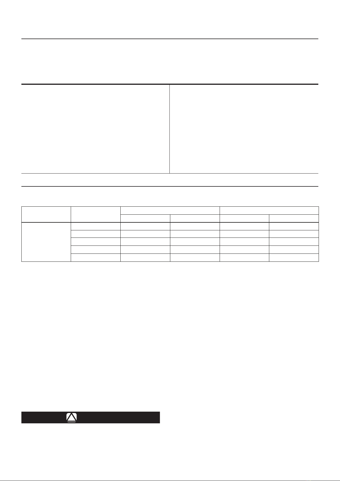
Table 1. Outlet Pressure Ranges
PNEUMATIC-LOADED
PILOT TYPE
SPRING-LOADED
PILOT TYPE
NOZZLE Ø OUTLET PRESSURE RANGE (Pd)
mm inch bar psig
114
114E 4 0.16 1 to 4.8 14.5 to 69.6
071E 4 0.16 4.8 to 18 69.6 to 261
236 3.2 0.13 18 to 35 261 to 508
227 3.2 0.13 35 to 47 508 to 682
222 3.2 0.13 47 to 60 682 to 870
Europe, Middle East and Africa Only

Type 114PL
3
Pu: INLET PRESSURE
Pd: OUTLET PRESSURE
Pm: MODULATED PRESSURE
RP: PILOT REJECT
IP: PILOT IMPULSE
Figure 2. Type 114PL Operational Schematics
Before installation, make sure that there
is no damage to or debris in the system.
Make sure that all tubing and piping are
clean and unobstructed.
The battery must be installed on
horizontal pipeline. Installation
according to EN 12186 is recommended.
When assembling with adjacent
elements take care not to create
pressure force on the body. The
assembling elements (bolts, O-rings
and flanges) should be compatible with
the geometry and working conditions of
the equipment.
Connect the impulse line keeping a
minimum distance of 4 x D to a straight
run of the outlet pipe.
No modification should be made
to the structure of the equipment
(drilling, grinding, soldering...). It is
recommended to install a servicing
valve on the outlet pipeline to facilitate
adjustments and bleeding off to
the atmosphere.
The equipment should not receive any
type of shock, especially the release
relay. The user should verify or carry out
a protection adapted to the environment.
The action of fire, seismic and lightening
are not taken into consideration in
standard regulators. If required, a
special product selection and/or specific
calculations may be supplied according
to specific requirements.
A regulator may vent some gas to
the atmosphere.
In hazardous or flammable gas service,
vented gas may accumulate, causing
personal injury, death or property
damage due to bursting of pressure
retaining parts.
Vent a regulator in hazardous gas
service to a remote, safe location
away from air intakes or any
hazardous location.
The vent line or stack opening must
be protected against condensation
or clogging.
IP
Pd
Pm
RP
R1
Pu
Europe, Middle East and Africa Only

Type 114PL
Facebook.com/EmersonAutomationSolutions
LinkedIn.com/company/emerson-automation-solutions
Twitter.com/emr_automation
Emerson Automation Solutions
General Installation
1. Install the regulator so that the flange connected
to the spring-loaded pilot’s feeding is in the
inlet side.
2. Use gaskets between pipeline and system flanges.
3. Connect the sensing line to the downstream.
Startup and Adjustment
1. Make sure all block valves, vent valves and
control line valve(s) are closed.
2. Completely unscrew the spring-loaded pilot
adjusting screw.
3. Slowly open the spring-loaded pilot feeding valve.
4. Screw the pilot adjusting screw until reach
the setpoint.
Maintenance
Disassembly
Check the absence of pressure between inlet and
outlet valves.
Recommended Frequency
Every year:
• Disassemble the manometric boxes and nozzles.
• Control O-rings, diaphragms, grease.
Parts Ordering
When corresponding with your local Sales Office
about this regulator, include the type number and all
other pertinent information stamped on the nameplate.
Specify the 11-character part number when ordering
new parts. See Type BSL85 Instruction Manual,
D103711X012, for the parts list.
Europe, Middle East and Africa Only
Fisher.com
Americas
McKinney, Texas 75070 USA
T +1 800 558 5853
+1 972 548 3574
Europe
Bologna 40013, Italy
T +39 051 419 0611
Asia Pacic
Singapore 128461, Singapore
T +65 6777 8211
Middle East and Africa
Dubai, United Arab Emirates
T +971 4 811 8100
D104438X012 © 2019 Emerson Process Management Regulator
Technologies, Inc. All rights reserved. 03/19.
The Emerson logo is a trademark and service mark of Emerson
Electric Co. All other marks are the property of their prospective owners.
Fisher™ is a mark owned by Fisher Controls International LLC, a
business of Emerson Automation Solutions.
The contents of this publication are presented for information purposes
only, and while eort has been made to ensure their accuracy, they are
not to be construed as warranties or guarantees, express or implied,
regarding the products or services described herein or their use or
applicability. All sales are governed by our terms and conditions, which
are available on request. We reserve the right to modify or improve the
designs or specications of our products at any time without notice.
Emerson Process Management Regulator Technologies, Inc does not
assume responsibility for the selection, use or maintenance of any
product. Responsibility for proper selection, use and maintenance of any
Emerson Process Management Regulator Technologies, Inc. product
remains solely with the purchaser.
Popular Water System manuals by other brands

Zip
Zip HydroTap G4 Install instructions

Albixon
Albixon HIDROLIFE Installation and user guide

IXOM
IXOM Medora GridBee GF10000C owner's manual

aarke
aarke CARBONATOR instruction manual

Apec Water
Apec Water ROES-UV75 Installation instructions & owner's manual

WaterLogic
WaterLogic BLUPURA FIZZ 80 Preinstallation manual

EINHELL
EINHELL GC-AW 6333 Original operating instructions

PUREWASH
PUREWASH ALTO 10 Getting started

Pelican
Pelican WF6 owner's manual

Elkay
Elkay ezH2O EZWSR 1D Series Installation & use manual

HydraMaster
HydraMaster Diamond Products GTXR+ Owner's Guide and Maintenance Logs

Kenmore
Kenmore 625.385010 owner's manual