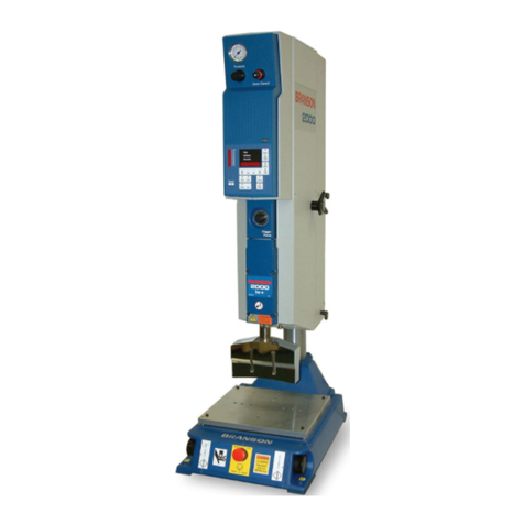
Emerson BRANSON MWX100 User manual

ii DCM01241 REV. 03
Introduction
This is the product manual for your BRANSON Metal Welding ultrasonic welding system.
Several combined Instruction Sets form the contents of this manual. This section contains
information which relates most uniquely to you as the customer, your particular system
and application. It also documents other Instruction Sets used in the manual. The figure
below illustrates how the manual is organized.
Branson Metal Welding Product Manual
Special Information Instruction Set
General Information Instruction Set
Actuator Instruction Set
Controller Instruction Set
(Other) Instruction Set (s)

DCM01241 REV. 03 iii
Using this manual
It is highly recommended that you read and understand the contents of this manual prior
to operating your Branson Metal Welding system. Each Instruction Set has a table of
contents and is intended to logically group information in a manner which the user will find
convenient.
Classification of Hazards
The safety indications in this manual are divided into different classes. The figure below
shows the assignment of symbols (pictograms) and signal words to the specific hazards
and its potential consequence.
DANGER
A potentially dangerous situation that could cause injury to persons
and serious damage to equipment.
CAUTION
A situation that may cause damage to the equipment.
NOTICE
Useful information, an application hint or other important or useful
information.

A
B
C
D
E
F
G
H
A
B
C
D
E
F
G
H
12345678910
12345678910
SOLID EDGE
SIZE
D
DWG NO REV
SCALE: SHEET 1 OF 4
MATERIAL:
FINISH:
3RD ANGLE ROJECTION
INCHES
( MM )
125
SURFACE FINISH
SECONDARY DIMENSIONS
ARE ROVIDED FOR
REFERENCE ONLY
This RO RIETARY Document is
property of Branson Ultrasonics
Corp., Danbury, CT.
It is confidential in nature,
non-transferable, and issued with
the clear understanding that it is
not traced or copied without
permission and is returnable upon
demand.
Article or material must comply
with requirements stipulated by
RoHS in its current version.
Material Spec.
Finish Spec.
N/A
N/A
N/A
N/A
1:1
--20
159-134-341
DRAWN
CHECKED
A ROVED
NAME DATE
TITLE
ACTR MWX 100 S OT WELD
ERS
DAS
DAS
7/09/09
7/09/09
7/09/09
NO
3 Important
NO
35.155 lbm
AGENCY ART
BUC CLASSIFICATION
I CLASSIFICATION
WEIGHT
GD & T Standard ANSI 14Y.5
UNLESS OTHERWISE S ECIFIED
DIMENSIONS ARE IN INCHES
AND TOLERANCES ARE:
2 LACE DECIMALS u.015
3 LACE DECIMALS u.005
4 LACE DECIMALS u.0005
ANGLES u1v FRACTIONS u1/32
REVISIONS
ZONE REV DESCRI TION DATE ECN/ECO DRAWN A R.
--- 1 U DATED ITEM 28, DELETE BALLOONS 98 & 97. ADDED BALLOON 102. ADDED NOTE 3 ON
AGE 2.
9/29/09 0-2153 --- DAS
--- 2 U DATED BALLOONS 44,78,79,80,82. DELETED BALLOON 81 ADDED BALLOONS 103,104, &
105.
10/28/09 0-2159 --- DAS
--- 3 U DATED BACK LABELS OSITION. 1/7/10 0-2163 ERS MGD
--- 4 REDRAWN IN SOLID EDGE. 7/30/10 18547 WI RO D.SULIK
9B 05 U DATED BEZEL BALLOON 84 AND LABEL BALLOON 89 SHEET 4 11/16/11 19105 JVL ERS
--- 06 ADDED WARNING LABEL 100-065-613 BALLOON 106 (page 4) 12/21/11 19151 JVL MD
--- 07 REMOVED ITEM #54 02/24/12 19207 CRS JJF
B7(SH3) 08 ADDED DETAIL A FOR LABEL 100-065-1162 09/03/12 19565 CRS ERS
C6(SHT3) 09 LABEL "CE" REMOVED 6/20/13 20104 JVL ERS
B3 (SH1),A10
(SH4)
10 ADDED CALLOUT ON BALLOON 87, AND ADDED NOTE 1 05/05/15 21151 DHM AAAH
--- 11 ADD 'SEE NOTE 5' TO BALLOON 102; MOVE SH1 NOTE 1 TO SH2 AS NOTE 4, CHANGE
SH4 'SEE NOTE 1' TO 'SEE NOTE 4' IN BALLOON 87; ADD NOTE 5 IN SH2; ADD 'USE
LOCTITE 545' TO BALLOON 35,36;
6/09/15 21263 FZHAO ERS
G7 (SH2) 12 ADDED NOTE 6 04/13/16 21675 VADV VADV
D3, D6, G7 (SH2);
B6 (SH4)
13 RE LACED BALLOON 31, 32 & 33 WITH 203-897 BALLOON 107; RE LACED 200-298-295
WITH 203-693 SAME BALLOON 34; RE LACED 200-098-954 WITH 200-098-844 SAME
BALLOON 75.
07/05/17 22166 VADV MGD
A10 (SH4) 14 RE LACED SEE NOTE 4 TO SEE NOTE 3. 8/10/17 22191 VADV VADV
--- 15 U DATED ER IM ACT ANALYSIS. 9/19/17 22210 AAMG VADV
--- 16 U DATED ER IM ACT ANALYSIS. 9/25/17 22221 AAMG VADV
G7, G8-G9 (SH3) 17 ADDED BALLOON 96 (HOSE 200-110-078 QTY. CHANGED FROM 0.10417 FT to 1.1875 FT.) 03/01/18 101019 VADV VADV
--- 18 U DATED ER IM ACT ANALYSIS. 2/6/20 102291 OZG HTR
--- 19 ADDED /N 200-298-005 QTY 2 BALLOON 108 AND 1017376 QTY 1 BALLOON 109. 4/14/20 102516 OZG VADV
B3, D6 20 CHANGED /N 200-298-287 WITH 100-298-315 SAME QTY & BALLOON. 4/20/21 103115 OZG VADV
.79
20.0
1.00
25.4
10 REF
11 REF
10
11
7
82X
5 2X
6 16X
3
2
4
12 2X
.20
5.1
12 REF
28 REF
1
13
92X
102 SEE NOTE 5
109
1082X
109 1082X

A
B
C
D
E
F
G
H
A
B
C
D
E
F
G
H
12345678910
12345678910
SOLID EDGE
SIZE
D
DWG NO REV
SCALE: SHEET 2 OF 4
MATERIAL:
FINISH:
3RD ANGLE ROJECTION
INCHES
( MM )
125
SURFACE FINISH
SECONDARY DIMENSIONS
ARE ROVIDED FOR
REFERENCE ONLY
This RO RIETARY Document is
property of Branson Ultrasonics
Corp., Danbury, CT.
It is confidential in nature,
non-transferable, and issued with
the clear understanding that it is
not traced or copied without
permission and is returnable upon
demand.
Article or material must comply
with requirements stipulated by
RoHS in its current version.
Material Spec.
Finish Spec.
N/A
N/A
N/A
N/A
1:2
--20
159-134-341
DRAWN
CHECKED
A ROVED
NAME DATE
TITLE
ACTR MWX 100 S OT WELD
ERS
DAS
DAS
7/09/09
7/09/09
7/09/09
NO
3 Important
NO
35.155 lbm
AGENCY ART
BUC CLASSIFICATION
I CLASSIFICATION
WEIGHT
GD & T Standard ANSI 14Y.5
UNLESS OTHERWISE S ECIFIED
DIMENSIONS ARE IN INCHES
AND TOLERANCES ARE:
2 LACE DECIMALS u.015
3 LACE DECIMALS u.005
4 LACE DECIMALS u.0005
ANGLES u1v FRACTIONS u1/32
REVISIONS
ZONE REV DESCRI TION DATE ECN/ECO DRAWN A R.
--- --- SEE SHEET 1 --- --- --- ---
38 4X
24 4X
NOTES:
1. ALIGNMENT OF ITEMS #14, 15 AND 23 CRITICAL.
2. ALIGN ITEM #21 TO DOWEL INS #25.
3. THE HOSE 104-109 USED IN THE ASSEMBLY MUST
HAVE 11 SEGMENTS.
4. UNLESS OTHERWISE S ECIFIED A LY LOCTITE 222 TO
ALL THREADS ON ASSEMBY, EXCE T FOR BALLOON 102.
5. A LY RTV DOW-CORNING 3145, RTV ASI388, DOW
CORNING 738 OR EQUIVALENT, ON J2, J4, J6, AFTER
SETTING U THE ACTUATOR.
6. THE DIMENSION OF 0.813in FOR SCREW 203-897 WILL BE
FACTORY SET RIOR TO SHI MENT.
18 4X
19 USE LOCTITE 242
20 USE LOCTITE 242
14
244X 21
10
28
27
16
414X
40
39 25 2X
.50 DE TH
22 4X
26 2X
6 2X
24 2X
37
29
302X
34
924X
17
232X
15
382X
36
35
USE LOCTITE 545
USE LOCTITE 545
107SEE NOTE 6
1082X
109

A
B
C
D
E
F
G
H
A
B
C
D
E
F
G
H
12345678910
12345678910
SOLID EDGE
SIZE
D
DWG NO REV
SCALE: SHEET 3 OF 4
MATERIAL:
FINISH:
3RD ANGLE ROJECTION
INCHES
( MM )
125
SURFACE FINISH
SECONDARY DIMENSIONS
ARE ROVIDED FOR
REFERENCE ONLY
This RO RIETARY Document is
property of Branson Ultrasonics
Corp., Danbury, CT.
It is confidential in nature,
non-transferable, and issued with
the clear understanding that it is
not traced or copied without
permission and is returnable upon
demand.
Article or material must comply
with requirements stipulated by
RoHS in its current version.
Material Spec.
Finish Spec.
N/A
N/A
N/A
N/A
1:1
--20
159-134-341
DRAWN
CHECKED
A ROVED
NAME DATE
TITLE
ACTR MWX 100 S OT WELD
ERS
DAS
DAS
7/09/09
7/09/09
7/09/09
NO
3 Important
NO
35.155 lbm
AGENCY ART
BUC CLASSIFICATION
I CLASSIFICATION
WEIGHT
GD & T Standard ANSI 14Y.5
UNLESS OTHERWISE S ECIFIED
DIMENSIONS ARE IN INCHES
AND TOLERANCES ARE:
2 LACE DECIMALS u.015
3 LACE DECIMALS u.005
4 LACE DECIMALS u.0005
ANGLES u1v FRACTIONS u1/32
GROUND UNIT
BEFORE O ERATING
DISCONNECT
AIR AND OWER
BEFORE SERVICING
AIR INLET
CAUTION
IMPORTANT
AIR SU LY MUST BE FREE OF OIL AND WATER
MAX. RESSURE 690kpa/6.89bar
100 SI MAX.
C
C
93
96
63
64
94
42 464544
55
68
69 A
A
6 2X
73 2X
72 2X
51
70
48
58
442X
49
52
100
101
60
91 3X
59 71
62
65
61
SECTION B-B
B
B
2X
2X
2X
SECTION C-C
SECTION A-A
REVISIONS
ZONE REV DESCRI TION DATE ECN/ECO DRAWN A R.
--- --- SEE SHEET 1 --- --- --- ---
FILTER
EXHAUST
AIR IN
MAIN COOLING
FLOW CONTROL
TO CONVERTER
CONVERTER
COOLING
FLOWCONTROL TO HORN
U S EED
FLOW CONTROL
CYLINDER
QUICK
EXHAUST
RESSURE
REGULATOR
VALVE 1
HORN
DOWN S EED
FLOW CONTROL
EXHAUST
EXHAUST
VALVE 2
COOLING
ORT LUG
2 LCS
R
A
B
A
B
R
NEUMATIC DIAGRAM
53
56 57
50
43
53
FOR UNITS BUILD IN CHINA
USE LABEL 100-065-1162
SEE DETAIL A
66 67 2X
96
DETAIL A

A
B
C
D
E
F
G
H
A
B
C
D
E
F
G
H
12345678910
12345678910
SOLID EDGE
SIZE
D
DWG NO REV
SCALE: SHEET 4 OF 4
MATERIAL:
FINISH:
3RD ANGLE ROJECTION
INCHES
( MM )
125
SURFACE FINISH
SECONDARY DIMENSIONS
ARE ROVIDED FOR
REFERENCE ONLY
This RO RIETARY Document is
property of Branson Ultrasonics
Corp., Danbury, CT.
It is confidential in nature,
non-transferable, and issued with
the clear understanding that it is
not traced or copied without
permission and is returnable upon
demand.
Article or material must comply
with requirements stipulated by
RoHS in its current version.
Material Spec.
Finish Spec.
N/A
N/A
N/A
N/A
1:2
--20
159-134-341
DRAWN
CHECKED
A ROVED
NAME DATE
TITLE
ACTR MWX 100 S OT WELD
ERS
DAS
DAS
7/09/09
7/09/09
7/09/09
NO
3 Important
NO
35.155 lbm
AGENCY ART
BUC CLASSIFICATION
I CLASSIFICATION
WEIGHT
GD & T Standard ANSI 14Y.5
UNLESS OTHERWISE S ECIFIED
DIMENSIONS ARE IN INCHES
AND TOLERANCES ARE:
2 LACE DECIMALS u.015
3 LACE DECIMALS u.005
4 LACE DECIMALS u.0005
ANGLES u1v FRACTIONS u1/32
REVISIONS
ZONE REV DESCRI TION DATE ECN/ECO DRAWN A R.
--- --- SEE SHEET 1 --- --- --- ---
1032X 1056X
6 2X
83
78
828X
80
694X
84
89
88
906X
85 76 262X
74 2X
75 8X
446X
77
448X
95
28 REF
62X
99
1064X
1046X
79
86
87
SEE NOTE 3

ii DCM00003 REV. 06
Introduction
This Instruction Set includes common information which relates to Branson products. It
will help you in setting up your system and to understand the fundamentals of the
ultrasonic metal welding process.
Thank You
Thank you, and congratulations on selecting Branson MWX100/ ULTRASPLICE Systems for
your welding production. This system has been developed to produce the highest quality
welds at the lowest cost per weld.
If you should experience difficulty or have any recommendations for improvement, please
do not hesitate to contact us.
Please be advised that the MWX100/ ULTRASPLICE machine is protected under the United
States and International patents listed below. This operator’s manual is also protected by
copyright and may not be copied without prior written permission by Branson.

DCM00003 REV. 06 iii
Trademarks
MWX100 and ULTRASPLICE are registered trademarks of Branson Ultrasonics Corp.
Copyright
MWX100 Computer Software and the MWX100 Manual are copyrighted 1994, 1995, 1996,
1997 by Branson Ultrasonics Corp.

iv DCM00003 REV. 06

DCM00003 REV. 06 v
Table of Contents
Chapter 1: Safety and Support
1.1 Intended Use . . . . . . . . . . . . . . . . . . . . . . . . . . . . . . . . . . . . . . . . . . . . . . . . . . 2
1.2 Safety, Personal . . . . . . . . . . . . . . . . . . . . . . . . . . . . . . . . . . . . . . . . . . . . . . . . 3
1.3 Maintenance Safety . . . . . . . . . . . . . . . . . . . . . . . . . . . . . . . . . . . . . . . . . . . . . . 4
1.4 Safety, System . . . . . . . . . . . . . . . . . . . . . . . . . . . . . . . . . . . . . . . . . . . . . . . . . 5
1.5 Contacting Branson . . . . . . . . . . . . . . . . . . . . . . . . . . . . . . . . . . . . . . . . . . . . . . 6
1.6 Warranty . . . . . . . . . . . . . . . . . . . . . . . . . . . . . . . . . . . . . . . . . . . . . . . . . . . . . 8
Chapter 2: Introduction
2.1 Ultrasonic Theory . . . . . . . . . . . . . . . . . . . . . . . . . . . . . . . . . . . . . . . . . . . . . . .10
2.2 Terminology . . . . . . . . . . . . . . . . . . . . . . . . . . . . . . . . . . . . . . . . . . . . . . . . . . .16
Chapter 3: Shipping and Handling
3.1 Unpacking, Handling & Installation . . . . . . . . . . . . . . . . . . . . . . . . . . . . . . . . . . .22
Chapter 4: Troubleshooting
4.1 Troubleshooting . . . . . . . . . . . . . . . . . . . . . . . . . . . . . . . . . . . . . . . . . . . . . . . .26
4.2 Weld Overload . . . . . . . . . . . . . . . . . . . . . . . . . . . . . . . . . . . . . . . . . . . . . . . . .27
4.3 Low Air Pressure . . . . . . . . . . . . . . . . . . . . . . . . . . . . . . . . . . . . . . . . . . . . . . . .28
4.4 Ready Check. . . . . . . . . . . . . . . . . . . . . . . . . . . . . . . . . . . . . . . . . . . . . . . . . . .29
4.5 Troubleshooting Guide . . . . . . . . . . . . . . . . . . . . . . . . . . . . . . . . . . . . . . . . . . . .30
Chapter 5: Maintenance
5.1 Periodic Maintenance . . . . . . . . . . . . . . . . . . . . . . . . . . . . . . . . . . . . . . . . . . . . .34

vi DCM00003 REV. 06

DCM00003 REV. 06 vii
List of Figures
Chapter 1: Safety and Support
Chapter 2: Introduction
Figure 2.1 Transforming Electrical Energy into high frequency mechanical vibration . . . . . . . . .10
Figure 2.2 High frequency vibration Welding . . . . . . . . . . . . . . . . . . . . . . . . . . . . . . . . . . . .10
Figure 2.3 Weld ‘power graph’ (weld footprint). . . . . . . . . . . . . . . . . . . . . . . . . . . . . . . . . . .12
Figure 2.4 Pressure, Power, and Time relationship . . . . . . . . . . . . . . . . . . . . . . . . . . . . . . . .12
Figure 2.5 Weld Time . . . . . . . . . . . . . . . . . . . . . . . . . . . . . . . . . . . . . . . . . . . . . . . . . . . .13
Figure 2.6 Amplitude. . . . . . . . . . . . . . . . . . . . . . . . . . . . . . . . . . . . . . . . . . . . . . . . . . . . .13
Figure 2.7 Power, Time, and Energy relationship . . . . . . . . . . . . . . . . . . . . . . . . . . . . . . . . .14
Figure 2.8 Resonant Frequency . . . . . . . . . . . . . . . . . . . . . . . . . . . . . . . . . . . . . . . . . . . . .14
Chapter 3: Shipping and Handling
Chapter 4: Troubleshooting
Chapter 5: Maintenance

viii DCM00003 REV. 06

x DCM00003 REV. 06

DCM00003 REV. 06 1
Chapter 1: Safety and Support
1.1 Intended Use . . . . . . . . . . . . . . . . . . . . . . . . . . . . . . . . . . . . . . . . . . . . 2
1.2 Safety, Personal . . . . . . . . . . . . . . . . . . . . . . . . . . . . . . . . . . . . . . . . . . 3
1.3 Maintenance Safety . . . . . . . . . . . . . . . . . . . . . . . . . . . . . . . . . . . . . . . 4
1.4 Safety, System . . . . . . . . . . . . . . . . . . . . . . . . . . . . . . . . . . . . . . . . . . . 5
1.5 Contacting Branson . . . . . . . . . . . . . . . . . . . . . . . . . . . . . . . . . . . . . . . 6
1.6 Warranty. . . . . . . . . . . . . . . . . . . . . . . . . . . . . . . . . . . . . . . . . . . . . . . . 8

2 DCM00003 REV. 06
1.1 Intended Use
This equipment is for the joining of metal parts using ultrasonic energy. A complete
system includes an actuator, controller and tooling (which delivers mechanical energy to
the work pieces). Some systems also include special fixturing and machine automation.
Branson systems may only be utilized to weld soft, ductile, metal parts together with
Branson-supplied weld tooling (such as horns, tips, anvils, and converters) unless an
explicit, written, contrary agreement between the ordering party and Branson has been
consummated.
Other manuals for BRANSON MWX100
1
Table of contents
Other Emerson Welding System manuals
Popular Welding System manuals by other brands

Chicago Electric
Chicago Electric 96712 Owner's manual & safety instructions

Dukane
Dukane iQ Series operating instructions

Clarke
Clarke EASIARC 165 Operation & maintenance instructions

Lincoln Electric
Lincoln Electric ACTIVE8 Operator's manual

WIA
WIA Weldmatic 256 Operator's manual

AXXAIR
AXXAIR SATO-40E41 Original instructions