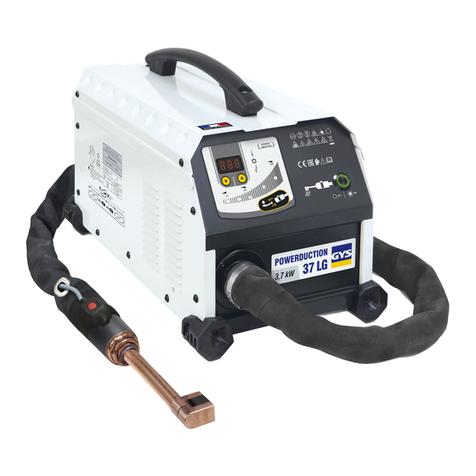
GYS PROTIG 201 AC/DC User manual

73502_V3_24/09/2020
FR 2-15 / 97-104
EN 16-28 / 97-104
PROTIG
201 AC/DC
201L AC/DC
DE 29-41 / 97-104
ES 42-54 / 97-104
RU 55-68 / 97-104
www.gys.fr
Find more languages of user manuals on our website
IT 83-96 / 97-104
NL 69-82 / 97-104

WARNING - SAFETY RULES
GENERAL INSTRUCTIONS
Read and understand the following safety instructions before use.
Any modication or updates that are not specied in the instruction's manual should not be undertaken.
The manufacturer is not liable for any injury or damage caused due to non-compliance with the instructions featured in this manual. In the event of
problems or uncertainties, please consult a qualied person to handle the installation properly.
ENVIRONMENT
This equipment must only be used for welding operations in accordance with the limits indicated on the descriptive panel and/or in the user manual.
Safety instructions must be followed. In case of improper or unsafe use, the manufacturer cannot be held liable.
This equipment must be used and stored in a room free from dust, acid, ammable gas or any other corrosive agent. Operate the machine in an
open, or well-ventilated area.
Operating temperature:
Use between -10 and +40°C (+14 and +104°F).
Storage between -20 and +55°C (-4 and 131°F).
Air humidity:
Lower or equal to 50% at 40°C (104°F).
Lower or equal to 90% at 20°C (68°F).
Altitude:
Up to 1000 meters above sea level (3280 feet).
INDIVIDUAL PROTECTIONS AND OTHERS
Arc welding can be dangerous and can cause serious injury or even death.
Welding exposes the user to dangerous heat, arc rays, electromagnetic elds, risk of electric shock, noise and gas fumes. People wearing pacemakers
are advised to consult a doctor before using the welding machine. To protect oneself as well as others, ensure the following safety precautions are
taken :
In order to protect you from burns and radiations, wear clothing without turn-up or cuffs. These clothes must be insulating, dry,
reproof, in good condition and cover the whole body.
Wear protective gloves which guarantee electrical and thermal insulation.
Use sufcient welding protective gear for the whole body: hood, gloves, jacket, trousers... (varies depending on the application/
operation). Protect the eyes during cleaning operations. Contact lenses are prohibited during use.
It may be necessary to install reproof welding curtains to protect the area against arc rays, weld spatter and sparks. Inform the
people around the working area to never look at the arc nor the molten metal, and to wear protective clothes.
Ensure ear protection is worn by the operator if the work exceeds the authorised noise limit (the same applies to any person in
the welding area).
Keep hands, hair and clothes away from moving parts such as fans, and engines.
Never remove the safety covers from the cooling unit when the machine is plugged in. The manufacturer is not liable for any injury
or damage due to non-compliance with the safety precautions.
Parts that have just been welded will be hot and may cause burns when touched. During maintenance work on the torch or the
electrode holder, you should make sure it's cold enough and wait at least 10 minutes before any intervention. When using a wa-
ter-cooled torch, make sure that the cooling unit is switched on to avoid any burns that could potentially be caused by the liquid.
It is important to secure the working area before leaving it to ensure protection of the goods and the safety of people.
Fumes, gas and dust produced during welding are hazardous to health. It is mandatory to ensure adequate ventilation and/or extraction
to keep fumes and gas away from the work area. Using an air fed welding helmet is recommended in case of insufcient ventilation in the workplace.
Check that the suction is effective by referring to the recommended safety regulations.
Precautions must be taken when welding in small areas, and the operator will need supervision from a safe distance. In addition, the welding of certain
materials containing lead, cadmium, zinc, mercury or beryllium may be particularly harmful.
Also remove any grease on the metal pieces before welding.
Gas cylinders must be stored in an open or ventilated area. They must be stored vertically and held by a support or trolley to limit the risk of fall.
WELDING FUMES AND GAS
16
EN
Translation of the original instructions
PROTIG 201 AC/DC - 201L AC/DC

Do not weld in areas where grease or paint are stored.
Protect the entire welding area. Flammable materials must be moved to a minimum safe distance of 11 meters.
A re extinguisher must be readily available near the welding operations.
Be careful of spatter and sparks, even through cracks. It can be the source of re or explosion.
Inammable material, explosive material, containers under pressure must stay at a safety distance.
Welding in closed containers or pipes is forbidden and, if they are opened, they must be emptied of any ammable or explosive material (oil, fuel,
gas ...).
Grinding operations should not be carried out close to the power supply or any ammable materials.
Gas leaking from the cylinders can lead to suffocation if present in high concentration around the work area (ventilation required).
Transport must be done safely: cylinders closed and welding machine switched off. They must be stored vertically and held by a support to limit the
risk of falling.
Close the cylinder between two uses. Beware of temperature variations and sun exposure.
The cylinder must not be in contact with a ame, electric arc, torch, earth clamp or all other sources of heat.
Always keep gas cylinders away from electrical circuits, and therefore never weld a cylinder under pressure.
Be careful when opening the cylinder valve, it is necessary to remove the tip of the valve and make sure that the gas meets your welding requirements.
SELECTRICAL SAFETY
The electrical mains used must have an earth terminal. Use the recommended fuse size.
An electric shock could cause serious injuries or potentially even deadly accidents.
Do not touch any live part of the machine (inside or outside) when it is plugged in (Torches, earth cable, cables, electrodes) because they are
connected to the welding circuit.
Before opening the device, it is imperative to disconnect it from the mains and wait 2 minutes, so that all the capacitors are discharged. Do not touch
the torch or electrode holder and the earth clamp at the same time.
Make sure to replace the torches and cables if they are damaged. This should be done by a qualied and authorised technician. Make sure that the
cable cross section is adequate with the usage (extensions and welding cables). Always wear dry clothes which are in good condition in order to be
isolated from the welding circuit. Wear insulating shoes, regardless of the workplace/environment in which you work in.
EMC CLASSIFICATION
This Class A machine is not intended to be used on a residential site where the electric current is supplied by the domestic
low-voltage power grid. There may be potential difculties in ensuring electromagnetic compatibility at these sites, due to
conducted interferences as well as radiation.
Provided that the impedance of the low-voltage public electrical network at the common coupling point is less than Zmax =
0,339 Ohms, this equipment complies with IEC 61000-3-11 and can be connected to public low-voltage electrical mains.
It is the responsibility of the installer or user of the equipment to ensure, in consultation with the distribution netwtork operator
if necessary, that the network impedance complies with the impedance restrictions.
This equipment complies with the CEI 61000-3-12 standard.
ELECTROMAGNETIC EMISSIONS
The electric current owing through any conductor causes electrical and magnetic elds (EMF). The welding current generates
an EMF around the welding circuit and the welding equipment.
The EMF electromagnetic elds can interfere with certain medical implants, such as pacemakers. Protective measures must be taken for people having
medical implants. For example, by restricting access to passers-by or conducting an individual risk evaluation for the welders.
All welders must use the following procedures to minimize exposure to electromagnetic elds from the welding circuit:
• position the welding cables together - x them with a clamp, if possible;
• position yourself (torso and head) as far away from the welding circuit as possible;
• never wrap the welding cables around the body;
• do not position the body between the welding cables. Hold both welding cables on the same side of your body;
• connect the earth clamp as close as possible to the area being welded;
• do not work too close to, do not lean and do not sit on the welding machine
• do not weld when transporting the welding machine or its wire feeder.
FIRE AND EXPLOSION RISKS
GAS CYLINDERS
17
EN
Translation of the original instructions
PROTIG 201 AC/DC - 201L AC/DC

People wearing pacemakers are advised to consult their doctor before using this device.
Exposure to electromagnetic elds while welding may have other health effects which are not
yet identied.
RECOMMENDATIONS TO ASSESS THE WELDING AREA AND WELDING INSTALLATION
Overview
The user is responsible for the installation and use of the arc welding equipment according to the manufacturer's instructions. If electromagnetic
disturbances are detected, the user is responsible for resolving the situation with the manufacturer's technical assistance. In some cases, this
corrective action may be as simple as earthing the welding circuit. In other cases, it may be necessary to construct an electromagnetic shield around
the welding power source and around the entire piece by tting input lters. In all cases, electromagnetic interferences must be reduced until they
are no longer inconvenient.
Welding area assessment
Before installing the machine, the user must evaluate the possible electromagnetic problems that may arise in the area where the installation is planned.
The following elements should be taken into account:
a) the presence (above, below and next to the arc welding machine) of other power cables, remote cables and telephone cables;
b) television transmitters and receivers;
c) computers and other hardware;
d) critical safety equipment such as industrial machine protections;
e) the health and safety of the people in the area such as people with pacemakers or hearing aids;
f) calibration and measuring equipment;
g) the isolation of other pieces of equipment which are in the same area.
The operator has to ensure that the devices and equipment used in the same area are compatible with each other. This may require extra precautions;
h) the time of day during the welding or other activities have to be performed.
The dimension of the cutting area that has to be considered depends on the size and shape of the building and the type of work undertaken. The area
taken into consideration might go beyond the limits of the installations.
Welding area assessment
Besides the welding area assessment, the assessment of the arc welding systems installation itself can be used to identify and resolve cases of
disturbances. The assessment of emissions must include in situ measurements as specied in Article 10 of CISPR 11: 2009. In situ measurements can
also be used to conrm the effectiveness of mitigation measures.
RECOMMENDATION ON METHODS OF ELECTROMAGNETIC EMISSIONS REDUCTION
a. National power grid : the arc welding machine must be connected to the national power grid in accordance in accordance with the manufacturer's
recommendation. In case of interferences, it may be necessary to take additional precautions such as the ltering of the power supply network.
Consideration should be given to shielding the power supply cable in a metal conduit or equivalent of permanently installed arc welding equipment. It
is necessary to ensure the electrical continuity of the frame along its entire length. The shielding should be connected to the welding current's source
to ensure good electrical contact between the conduct and the casing of the welding current source.
b. Maintenance of the arc welding equipment : The arc welding machine should be subject to a routine maintenance check according to the
recommendations of the manufacturer. All accesses, service doors and covers should be closed and properly locked when the arc welding equipment
is on. The arc welding equipment must not be modied in any way, except for the changes and settings outlined in the manufacturer's instructions.
The spark gap of the arc starts and arc stabilization devices must be adjusted and maintained according to manufacturer's recommendations.
c. Welding cables: Cables must be as short as possible, close to each other and close to the ground, if not on the ground.
d. Equipotential bonding: consideration should be given to bond all metal objects in the surrounding area. However, metal objects connected to
the workpiece increase the risk of electric shock if the operator touches both these metal elements and the electrode. It is necessary to insulate the
operator from such metal objects.
e. Earthing of the workpiece: When the part is not earthed due to electrical safety reasons or because of its size and its location (which is the case
with ship hulls or metallic building structures), the earthing of the part can, in some cases but not systematically, reduce emissions. It is preferable
to avoid the earthing of parts that could increase the risk of injury to the users or damage other electrical equipment. If necessary, it is appropriate
that the earthing of the part is done directly, but in some countries that do not allow such a direct connection, it is appropriate that the connection is
made with a capacitor selected according to national regulations.
f. Protection and shielding: The selective protection and shielding of other cables and devices in the area can reduce perturbation issues. The
protection of the entire welding area can be considered for specic situations.
TRANSPORT AND TRANSIT OF THE WELDING MACHINE
The machine is tted with handle(s) to facilitate transportation. Be careful not to underestimate the weight of the machine. The
handle(s) cannot be used for slinging.
Do not use the cables or torch to move the machine. The welding equipment must be moved in an upright position.
Do not place/carry the unit over people or objects.
Never lift the machine while there is a gas cylinder on the support shelf. The transport rules applying to each item are different.
EQUIPMENT INSTALLATION
• Put the machine on the oor (maximum incline of 10°).
• The machine must be placed in a sheltered area away from rain or direct sunlight.
• Provide an adequate area to ventilate the machine and access the controls.
• This equipment must be used and stored in a place protected from dust, acid, gas or any other corrosive substance.
• The machine protection level is IP21, which means:
- Protection against acess to dangerous parts from solid bodies of a ≥12.5mm diameter and,
- Protection against vertically falling drops.
• Power, extension and welding cables must be fully uncoil to avoid overheating.
Warning: Increasing the length of the torch or earth return cables beyond the maximum length specied by the manufacturer will increase the risk
of electric shock.
18
EN
Translation of the original instructions
PROTIG 201 AC/DC - 201L AC/DC
The manufacturer does not accept any liability in relation to damages caused to objects or harm caused to persons as the result of incorrect
and/or dangerous use of the machine.
MAINTENANCE / RECOMMENDATIONS
• Maintenance should only be carried out by a qualied person. A yearly maintenance is recommended.
• Ensure the machine is unplugged from the mains, and then wait 2 minutes before carrying out maintenance work. Inside, voltages and
currents are high and dangerous.
• Remove regularly the casing and any excess of dust. Take this opportunity to have the electrical connections checked by a qualied
person, with an insulated tool.
• Regularly check the condition of the power supply cable. If the power cable is damaged, it must be replaced by the manufacturer, its
after sales service or an equally qualied person to prevent danger.
• Ensure the vents of the device are not blocked to allow adequate air circulation.
• Do not use this equipment to thaw pipes, to charge batteries, or to start any engine.
INSTALLATION – PRODUCT OPERATION
Only qualied personnel authorized by the manufacturer should perform the installation of the cutting equipment. During set up, the operator must
ensure that the machine is unplugged.
DESCRIPTION
The PROTIG 201 AC/DC and PROTIG 201L AC/DC are inverter welding current sources for welding to the coated electrode (MMA) and refractory
electrode (TIG) in direct current (DC TIG ) and alternating current (AC TIG). The MMA process can weld all types of electrodes : rutile, basic, stain-
less and cast iron.
TIG welding requires gas shield protection of pure gas (Argon). The PROTIG 201L AC/DC incorporates a cooling unit as standard.
It is recommended to use the welding cables supplied with the unit in order to obtain the best performance.
POWER SUPPLY - POWER UP
• The PROTIG 201 AC/DC is supplied with a 16A plug type CEE7/7 and must only be used on a single-phase electrical installation (50-60 Hz) with 3
wires including one connected to earth. This machine has the "Flexible Voltage" feature and needs to be powered by an earthed electrical installation
between 110V and 240V (50 - 60Hz). For intensive use at 110 V, replace the original plug with a 32 A plug protected by a 32 A circuit breaker. The
user must ensure that the socket is accessible.
• The PROTIG 201L AC/DC is supplied with a 16A plug type CEE7/7 and must only be used on a single-phase electrical installation (50-60 Hz) with
3 wires including one connected to earth.
The absorbed effective current (I1eff) is displayed on the machine, for optimal use. Check that the power supply and its protection (fuse and/or
circuit breaker) are compatible with the current needed by the machine. In some countries, it may be necessary to change the plug to allow the use
at maximum settings.
• It switches to protection mode if the power supply voltage is over 265 V. To indicate this fault, the display shows Once the machine is in
protective mode, unplug the machine and plug it into an outlet supplying the correct voltage.
• Fan behaviour: in MMA mode, the fan works continuously. In TIG mode, the fan works only during welding, then stops after the machine has cooled
down.
• The arc priming and stabilisation device is designed for manual and mechanically guided operation.
WORKING OFF A GENERATOR
These machines can work on generators as long as the auxiliary power matches the requirements below:
- The voltage must be AC, always set as specied, and the peak voltage below 700V,
- The frequency must be between 50 and 60 Hz.
It is imperative to check these requirements as certain generators can create high voltage peaks that can damage these machines.
USE OF EXTENSION LEADS
All extension cables must have an adequate size and section, relative to the machine's voltage. Use an extension lead that complies with national
safety regulations.
Voltage input Length and thickness of the extension lead
< 45 m < 100 m
230 V 2.5 mm²
110 V 2.5 mm² 4 mm²
GAS CONNECTION
The machine has a pneumatic connection. Use the adapters originally supplied with the power source.
ACCESSORIES AND OPTIONS
Trolley Trolley Torch Manual remote control Foot pedal
19
EN
Translation of the original instructions
PROTIG 201 AC/DC - 201L AC/DC
201 201L 201 201L 045675 045682
039704 041257 038271 038202
ACTIVATION OF THE VRD FUNCTION (VOLTAGE REDUCTION DEVICE)
This device protects the welder. The welding current is delivered only when the electrode is in contact with the part (low resistance). As soon as the
electrode is removed, the VRD function lowers the voltage to a very low value.
The VRD function is originally disabled. However, this can be activated by means of an ON/OFF switch on the power source control board. To access
it, follow the steps below:
1. DISCONNECT THE PRODUCT FROM THE POWER SUPPLY BEFORE HANDLING.
2. Remove the screws to take the power source cover off.
3. Locate the switch on the control board (red box on diagram below - n° 2).
4. Turn the switch located on this control card ON. The red LED switches off.
5. The VRD function is activated.
6. Screw the power source cover back on.
7. On the interface (HMI), the LED for the VRD function is lighted :
To deactivate the VRD function, simply turn the switch located on the control board back to OFF. The VRD LED on the HMI is turned off.
1
2
It is possible to restore the factory settings of the welding machine. When the station is in sleep mode, press the sleep exit push button for 3 seconds.
The station then displays "3", "2", "1" and then resets the unit.
When the machine is plugged into the mains, it displays the software versions of the power and the HMI boards.
RESETTING THE WELDING STATION
DISPLAY OF SOFTWARE VERSIONS
20
EN
Translation of the original instructions
PROTIG 201 AC/DC - 201L AC/DC
HUMAN-MACHINE INTERFACE (HMI)
Sleep Mode /
Sleep Exit
Up current
button
Pre-gas
button
Downslope
Welding
current
Display
Cold current
button A/V display
selection
Creating /
Recalling /
Deleting JOBS
TIG AC
AC
Post gas
button
AC / DC
Sub-processes
Pulse
Frequency Button
Trigger
mode
Processes
Functions Pictograms MMA TIG DC TIG AC Comments
Sleep Mode / Sleep Exit • • • Button to put the product into and out of sleep mode.
Sub-processes • • In MMA process: access to "Pulse MMA"mode,
In TIG DC: access the "Pulse" or "Spot " modes.
AC/DC • • Choose between TIG "DC", TIG "AC" and TIG "AC - Easy".
AC • Select the parameter to be adjusted between "Frequency"
and "Balance".
A/V display selection • • By default the welding current is displayed on the HMI.
Pushing this button displays the welding voltage during or
after the welding cycle.
JOB • • • Allows you to recall, create and delete a job. Refer to the
JOB section for more information.
Pre-gas • • Setting the Pre-Gas time. This time corresponds to the time
it takes to purge the torch and to protect the area with gas
before ignition
Up slope current • • • Current rise ramp.
Pulse Frequency •Pulse frequency setting (only in TIG DC).
21
EN
Translation of the original instructions
PROTIG 201 AC/DC - 201L AC/DC

Cold current/Background
current) • • Cold current setting in PULSE mode.
Downslope • • Current lowering ramp setting.
Post gas • •
Post-Gas time setting. This time corresponds to the duration
of gas protection after the arc has been extinguished. It
protects the weld pool and the electrode against oxidisation
when the metal is cooling down.
HMI OPERATION AND DESCRIPTION OF ITS BUTTONS
• On / Off button
This key is used to activate or deactivate the machine from sleep mode. The sleep mode cannot be activated while the machine is welding.
•Welding process selection button
This key is used to select the welding process. Each successive press toggles between the following welding processes: TIG HF / TIG LIFT / MMA.
The LED indicates the selected process.
Note: the process selected by default at machine startup corresponds to the last process used before the last sleep or shutdown.
• Trigger mode selection button
Use this button to congure how the trigger is used. Each successive press toggles between the following modes: 2T / 4T / 4T LOG. The LED indicates
the selected mode.
Note: the trigger mode selected by default at machine startup corresponds to the last trigger mde used before the last sleep or shutdown. For more
information, refer to the section "Compatible Torches and Trigger Behavior".
•Selecting sub-processes button
This key is used to select the "Sub-process". Each successive press toggles between the following sub-processes: PULSE / SPOT (only in TIG mode)
/ MMA PULSE (only in MMA mode). The LED indicates the selected process.
Note: PULSE mode is only accessible in DC TIG mode.
SPOT mode is not accessible in 4T & 4T Log trigger conguration and in MMA PULSE welding mode.
Note: the sub-process selected by default at machine startup corresponds to the last sub-process used before the last sleep or shutdown.
•AC or DC current selection button
This key is used to select the current type when the TIG process is activated. Each successive press toggles between the following modes : DC / AC
/ AC - Easy. The LED indicates the selected process.
Note: the process selected by default at machine startup corresponds to the last process used before the last sleep or shutdown.
• Main incremental encoder
As default, the incremental encoder allows the adjustment of the welding current.. It is also used to set the values of other parameters which are then
selected via the associated keys. Once the parameter setting has been completed, it is possible to press the key of the parameter that has just been
set again so that the incremental encoder is again linked to the current setting. It is also possible to press another key related to another parameter to
adjust it. The buttons concerned are the BP1 to BP5 and the adjustment BP in AC. If no action is performed on the HMI for 2 seconds, the incremental
encoder is again linked to the welding current setting.
•Pre-Gas button
The Pre-Gas adjustment is done by pressing and releasing the Pre-Gas button and then activating the main incremental encoder. Pre-Gas value in-
creases when the incremental encoder is operated clockwise and decreases when it is operated anti-clockwise. Once the setting has been made, it
is possible to press and release the Pre-Gas button again to re-link the main incremental encoder to the current setting or to wait for 2 seconds. The
setting step is 0.1 sec. The minimum value is 0 sec. and the maximum value is 60 sec.
•Post-Gas button
The Post-Gas adjustment is done by pressing and releasing the Post-Gas button and then activating the main incremental encoder. Post-Gas value
increases when the incremental encoder is operated clockwise and decreases when it is operated anti-clockwise. Once the setting has been made, it
is possible to press and release the Post-Gas button again to re-link the main incremental encoder to the current setting or to wait for 2 seconds. The
setting step is 0.1 sec. The minimum value is 0 sec. and the maximum value is 60 sec.
•Up Slop or current control button
The curremt ramp-up setting is done by pressing and releasing the current ramp-up button and then by activating the main incremental encoder. Cur-
rent ramp-up value increases when the incremental encoder is operated clockwise and decreases when it is operated anti-clockwise. Once the setting
has been made, it is possible to press and release the current ramp-up button again to re-link the main incremental encoder to the current setting or
to wait for 2 seconds. The setting step is 0.1 sec. The minimum value is 0 sec. and the maximum value is 25 sec.
•Incremental encoder for fading or "Down Slop" adjustment
The "Down-Slop" incremental encoder is used to set the value of the current fading (clockwise increase and counterclockwise decrease). The value is
visible on the 7-segment display and remains displayed for 2 seconds if an action on the incremental encoder is performed.
•Cold current control button
When one of the 2 processes "HF TIG" or "LIFT TIG" is selected, the cold current setting button is used to adjust the value of the cold current (only
in 4T Log trigger conguration). The value can be adjusted between 20% and 99% of the welding current. The incremental step is 1%. This value is
also adjustable in the "TIG DC Pulse" and "MMA Pulse" processes.
22
EN
Translation of the original instructions
PROTIG 201 AC/DC - 201L AC/DC

• " AC " button
Use of the "AC" button in "AC - Easy" mode : Pressing this button gives access to the tungsten electrode diameter setting. The setting of this parame-
ter is done as follows:
- Press the "AC" key,
- Within 3 seconds, activate the incremental encoder. An clockwise rotation of this encoder leads to an increase in the electrode diameter and a
anti-clockwise rotation leads to a decrease in the value of the electrode diameter. The selected electrode value is visible on the HMI LEDs below the
AC Easy mode.
- Once the setting has been made, after 2 seconds without activating the incremental encoder, it is again linked to the current setting.
Using the " AC " button in " AC " mode : Pressing this button allows you to select and adjust the " Balance " and " Frequency " parameters (the asso-
ciated LED lights up according to the selected parameter). The incremental encoder acts on these 2 parameters values and must be actuated within
5 seconds. Beyond that, the power source will display the welding current again.
• Frequency adjustment in TIG AC (Frequency)
The welding current frequency setting for TIG AC ranges from 20 Hz to 200 Hz.
• Balance adjustment in TIG AC (Balance)
The welding balance setting for TIG AC ranges from 20 % to 60 %. The incremental step is 1%.
Note: The "AC" key is not active in "DC" mode.
HIDDEN MODE
A hidden mode is available for each of the welding processes: DC TIG, AC TIG and MMA. This mode is designed to allow the setting of additional
parameters for each of these processes.
The changes of the values of accessible parameters in the hidden mode are kept when saving a job.
Accessibility, navigation and settings in hidden mode:
DC TIG and AC TIG:
Access the hidden mode by pressing the (A/V) button for 3 seconds.
The machine now displays "CoU". By turning the main encoder, it is possible to access to " ISA", "TSA", "ISO", "TSO" and "ESC".
To access the setting of these parameters, press the A/V button again.
•CoU : Activate or deactivate the Cooling Unit by selecting "ON" or "OFF". The selection between "ON" and "OFF" is made by activating the main
encoder and then pressing the A/V button. This only applies to the "201 L AC/DC" version.
•ISA : Set the starting current. It is set as a percentage of the welding current setpoint. It can be adjusted between 10% and 200%. Validate the
entered setting by pressing the A/V button.
•TSA : Set the duration of the starting current. Time is adjustable from 0s to 10s, validate the entered setting by pressing the A/V button.
•ISO : Set the welding end current, it is set as a percentage of the welding current setpoint. It can be adjusted between 10% and 200%. Validate
the entered setting by pressing the A/V button.
•TSO : Set the duration of the welding current. Time is adjustable from 0s to 10s, validate the entered setting by pressing the A/V button.
•ESC : Press the A/V button to exit the hidden mode. You can also exit the hidden mode by waiting three seconds after setting a hidden mode
parameter. The display then returns to the welding current setpoint setting.
MMA :
Access the hidden mode by pressing the (A/V) button for 3 seconds.
The machine now displays "HST". By turning the main encoder it is possible to access "AST" and "ESC".
•HST : Set the duration of the HotStart. This time is adjustable from 0.1s to 2s. Validate the entered setting by pressing the A/V button.
•AST : Activate or deactivate the Antisticking by selecting "ON" or "OFF". Validate the entered setting by pressing the A/V button.
•ESC : Press the A/V button to exit the hidden mode. You can also exit the hidden mode by waiting three seconds after setting a hidden mode
parameter. The display then returns to the welding current setpoint setting.
COATED ELECTRODE WELDING (MMA)
CONNECTIONS AND RECOMMENDATIONS
• Connect the electrode holder and the earth clamp into the connectors provided for this purpose, taking care to respect the welding polarities and
intensities indicated on the electrodes boxes.
• Remove the electrode from the electrode holder when the machine is not in use.
• The machines have 3 features exclusive to Inverters:
- The Hot Start creates an overcurrent at the beginning of the weld to prevent sticking.
- The Arc Force creates an overcurrent which prevents the electrode from sticking to the weld pool.
- The Anti-Sticking technology makes it easier to unstick the electrode from the metal.
MMA PULSE
This MMA Pulse welding mode is suitable for applications in the vertical up position (PF). The pulse mode keeps the weld pool cold and eases the
transfer of matter. Without the pulse mode, vertical-up welding requires a difcult "Christmas tree" shape triangular movement. With the MMA Pulsed
mode, this movement is no longer required and a simple straight up movement is enough (depending on the thickness of the workpiece). If you
wish to widen your weld pool, a simple lateral movement is enough (similar to normal welding). This process allows greater control during vertical-up
welding. The pulse frequency is adjustable from 0.4 Hz to 20 Hz.
23
EN
Translation of the original instructions
PROTIG 201 AC/DC - 201L AC/DC
TUNGSTEN ELECTRODE WELDING WITH INERT GAS (TIG MODE)
CONNECTION AND ADVICE
• TIG DC and TID AC welding require gas protection (Argon).
• Connect the earth clamp to the positive connector (+). Connect the torch to the negative plug (–), the trigger cable and the gas hose.
• Make sure that the various components that make up the torch are present (clamp, collar support, diffuser and nozzle) and that they are in good
condition.
• The electrode selection is dened according to the TIG DC or AC welding current..
ELECTRODE SHARPENING
For optimal operation, it is recommended to use a sharpened electrode as follows:
a = Ø 0.5 mm
L = 3 x d for a low current.
L = d for a high current
CHOICE OF ELECTRODE DIAMETER
Ø Electrode
(mm)
TIG DC TIG AC
Pure tungsten Tungsten with oxides Pure tungsten Tungsten with oxides
1 10 > 75 A 10 > 75 A 15 > 55 A 10 > 70 A
1.6 60 > 150 A 60 > 150 A 45 > 90 A 60 > 125 A
2 75 > 180 A 100 > 200 A 65 > 125 A 85 > 160 A
2.5 130 > 230 A 170 > 250 A 80 > 140 A 120 > 210 A
3.2 160 > 310 A 225 > 330 A 150 > 190 A 150 > 250 A
4 275 > 450 A 350 > 480 A 180 > 260 A 240 > 350 A
~ 80 A per mm de Ø ~ 60 A per mm de Ø
CHOICE OF THE TYPE OF IGNITION
TIG HF: non-contact high-frequency ignition of the tungsten electrode on the workpiece.
TIG LIFT : Arcing by contact (for environments where HF is not desirable).
1. Place the torch in the welding position above the part (distance of about
2-3 mm between the electrode tip and the part).
2. Press the the torch trigger (the arc starts without contact using High
Frequency impulsions).
3.The initial welding current ows, the weld will be
continues according to the welding cycle.
1. Position the torch nozzle and the electrode tip on the workpiece and press
the torch button.
2. Tilt the torch until the electrode tip is about 2-3 mm away from the work-
piece. The arc starts.
3. Return the torch to the normal position to start the welding cycle.
TIG PROCESS SETTINGS
• TIG DC is dedicated to the welding of ferrous metals such as steel, stainless steel but also copper and its alloys, titanium.
• TIG AC is dedicated to the welding of aluminium and its alloys.
TIG DC WELDING
•TIG DC - Standard
The TIG DC Standard welding process allows high quality welding on most ferrous materials such as steel, stainless steel, but also copper and its
alloys, titanium... The many possibilities of current and gas management allow you to perfectly control your welding operation, from the ignition to
the nal cooling of your bead.
•TIG DC - Pulse
This pulsed current welding mode is a combination of high current pulses (I, welding pulse) and low current pulses (I_Cold, part cooling pulse). This
pulse mode allows to assemble pieces while while keeping the machine cooler. It is particularly recommended for assembling thin parts.
(e. g. : The welding current I is set to 100A and % (I_Cold) = 50%, i.e. a cold current = 50% x 100A = 50A. F(Hz) is set to 10 Hz, the signal period
will be 1/10 Hz = 100 ms. Every 100ms, a 100A pulse then a 50A pulse will succeed each other.
24
EN
Translation of the original instructions
PROTIG 201 AC/DC - 201L AC/DC
The choice of frequency
• If thin plate without TIG electrodes (< 0.8 mm), F(Hz) > 10Hz,
• If special metal requiring a welding pool sweep for degassing, then F(Hz) 5 < 100Hz.
The frequency adjustment in TIG DC pulsed is done by pressing and releasing the pulse frequency adjustment button and then operating the
main incremental encoder. Frequency value increases when the incremental encoder is operated clockwise and decreases when it is operated anti-
clockwise. This frequency ranges from 0.1 Hz to 2 KHz.
Example : = 1 KHz.
Once the setting has been done, press the frequency setting button again or wait 2 seconds for the power source to return to the main menu. Pulsed
DC welding is available for the "TIG HF" and "TIG LIFT" processes and the "2T" and "4T" trigger modes.
TIG AC WELDING
•TIG AC - Easy
This mode allows a quick use of AC welding by adjusting the electrode diameter (the selected value is indicated by the different LEDs on the HMI).
With this mode, "Balance" and "Frequency" settings parameters are unchangeable. The choice of the electrode diameter affects the welding current
and the scraping values as follows :
Electrode diameter Imin Imax Penetration and cleaning
1,6 mm 10 A 80 A 30 %
2,4 mm 45 A 120 A 37 %
3,2 mm 60 A 180 A 43 %
4,0 mm 75 A 200 A 50 %
With this mode, the frequency value is related to the welding current value as follows :
Current (A) Frequency (Hz)
10 > 40 117
41 > 90 100
91 > 140 79
141 > 170 70
171 > 200 60
When switching from "AC - Easy" to "AC" mode, the last welding parameters "AC - EASY" are retained and can be used as a basis for further
renement in "AC" (e.g. : welding frequency and balance).
• TIG AC - Standard
This TIG AC - Standard welding mode is dedicated to welding aluminium and its alloys (Al, AlSi, AlMg, AlMg, AlMn...). Alternating current (AC) includes
a cleaning phase which is essential for aluminium welding.
The balance: It allows the part to be cleaned during welding. The balance: It allows the part to be cleaned during welding.
The frequency: the frequency is used to adjust the concentration of the arc. A high frequency generates a concentrated arc. A low frequency
generates a wider arc.
High frequency Low frequency
The AC/DC current-frequency characteristic: In AC, the value of the welding current and its frequency are linked by the function below :
Current AC Current as a function
of Frequency
Fréquence (Hz)
Courant (A)
050 150100 200
150
200
Frequency
Up to 100 Hz it is possible to weld at a welding
current of 200 A. Between 100 Hz and 200
Hz, the maximum value of the welding current
decreases from 200 A to 150 A.
25
EN
Translation of the original instructions
PROTIG 201 AC/DC - 201L AC/DC
• TIG AC - Pulsed
The Pulse function is available in TIG AC - Easy and TIG AC - Standard. The pulse frequency is adjustable from 0.1 Hz to 10 Hz.
TIG SPOT DC or AC
The " SPOT" mode allows the pre-assembly of parts by tacking. The tacking time adjustment allows a better reproducibility and the realisation of
non-oxidised tack. As default, when the " SPOT " mode is selected, the start and the end of the welding is done at the trigger. However, the " F(Hz) "
button and the main encoder allow the user to rene this time. The time in this "SPOT" tacking mode is adjustable by 0.1 sec. at 60 sec. in steps of
0.1 sec. The ignition is then done with the trigger. To return to an undened spot time, simply select "0.0s".
JOBS MANAGEMENT
The current settings are automatically saved and loaded at start up. In addition to the current settings, it is possible to save and recall so-called "JOB"
congurations. The " JOB " button is used to save, recall or delete a conguration. 50 Jobs can be stored per welding process.
• Job Recall
- Apart from not being in the welding process, the recall of a job does not require any particular initial condition,
- Press the " JOB " button briey (not more than 2 sec.),
- " OUT " appears on the HMI display,
- With the incremental encoder, select a job number. Only the numbers associated with existing jobs appear on the display If no job is stored, the
HMI displays "- - - -".
- Once the job number has been selected, press the "JOB" button to conrm the conguration. The job number then ickers on the display, indicating
that the job has been loaded. The number continues to icker until another parameter is changed or until the torch trigger is pressed to start the
welding cycle.
•Job deletion
- Press the "JOB" button briey (not more than 2 sec.),
- "OUT" appears on the HMI display,
- With the incremental encoder, select a job number. Only numbers associated with existing jobs can be displayed,
- Press successively 3 times on the " JOB " button. The selected job is now deleted and the power source displays the welding current again.
• Job creation
- Adjust all desired welding parameters,
- Press and hold the " JOB " button for more than 3 seconds,
- The display shows "IN",
- Select a job number using the incremental encoder. Only numbers that are not already assigned to a previously saved job can be selected and are
shown on the display,
- Once the job number has been chosen, press the "JOB" button to validate and save it under the selected number,
- The job number then remains displayed, indicating that the save action has been completed. The number continues to be displayed until another
button or the torch trigger is activated.
Note: If all numbers are already assigned to saved jobs, the HMI displays "Full".
Precisions for a job reminder in TIG AC: The special feature of a job reminder in TIG AC is the display of the parameters related to the "AC" functions.
When a job conguring the station in "AC" is called up, the HMI then displays successively the values of the welding current (in A), the balance (in %)
and the frequency (in Hz) following a repetitive cycle. This cycle lasts until the torch trigger is pulled to start a welding cycle.
COMPATIBLE TORCHES AND TRIGGER TYPES
L
DB
P
L
DB
P
L
DB
P
For the 1 button torch, the button is called "main button".
For the 2 buttons torch, the rst button is called "main button" and the second button is called "secondary button".
2T MODE
t t
t t
t
t
T2
T1
Main button
T3
T1
Main button T2 T4
T3
T1
Main button T2 T4
Secondary button
or
>0.5s<0.5s<0.5s
T1: The main button is pressed, the welding cycle starts (PreGas, I_Start,
UpSlope and welding).
T2: The main button is released, the welding cycle is stopped (DownSlope,
I_Stop, PostGas).
For the double button torch and in 2T mode only, the secondary button
works like the main button.
26
EN
Translation of the original instructions
PROTIG 201 AC/DC - 201L AC/DC
4T MODE
t t
t t
t
t
T2
T1
Main button
T3
T1
Main button T2 T4
T3
T1
Main button T2 T4
Secondary button
or
>0.5s<0.5s<0.5s
T1: The main button is pressed, the cycle starts at PreGas and stops in the
I_Start phase.
T2: The main button is released, the cycle continues in UpSlope and in
welding.
T3: The main button is pressed, the cycle switches to DownSlope and stops
in I_Stop phase..
T4: The main button is released, the cycle ends with PostGas.
4T LOG MODE
t t
t t
t
t
T2
T1
Main button
T3
T1
Main button T2 T4
T3
T1
Main button T2 T4
Secondary button
or
>0.5s<0.5s<0.5s
T1: The main button is pressed, the cycle starts at PreGas and stops
in the I_Start phase.
T2: The main button is released, the cycle continues in UpSlope and
in welding.
LOG : this mode is used during welding :
- A brief press of the main button (<0.5s), the current switches
from I welding current to I cold and vice versa.
- The secondary button is kept pressed, the current switches from I
welding to I cold.
- The secondary button is released, the current switches from I cold
to I welding.
T3: A long press on the main button (>0.5 sec.), the cycle switches
to DownSlope and stops in the I_Stop phase.
T4: The main button is released, the cycle ends with PostGas.
For this mode it may be convenient to use the dual button torch option or dual button with potentiometer. The "up" command keeps the same function
as the single button or trigger torch. The secondary button can, when pressed, switch to the cold current. The welding torch potentiometer, when
present, allows the welding current to be adjusted from 50 % to 100 % of the setpoint.
COMMAND TRIGGER CONNECTOR
DB torch
L torch
NC
P
torch
P
L
DB
L
torch DB
torch DB + P
torch
Cabling diagram for the SRL 18 torch. Electric diagram based on type of torch used.
Torch type Wire description Pin
Torch with 2 triggers +
potentiometer Torch with 2 triggers Torch with 1 trigger Common/Earth 2 (green)
Switch trigger 1 4 (white)
Switch trigger 2 3 (brown)
Common/ Potentiometer
earth 2 (grey)
10 V 1 (yellow)
Cursor 5 (pink)
27
EN
Translation of the original instructions
PROTIG 201 AC/DC - 201L AC/DC
28
EN
Translation of the original instructions
PROTIG 201 AC/DC - 201L AC/DC
REMOTE CONTROL
The analog remote control operates in TIG and MMA processes.
Ref. 045699 External view Electric diagram according to the remote
control type.
1- Plug the remote control into the connection at the back of the machine.
2- The HMI detects the presence of a remote control and offers a selection between a "pedal" type remote control and a "potentiometer" type remote
control, accessible via the main incremental encoder.
Connection:
The product is equipped with a female socket for a remote control.
The specic 7 pin male plug (option ref.045699) enables connection to the different types of manual remote control or foot pedal. For the cabling
layout, please see the diagram below.
Type of remote control Wire description Pin
Foot pedal Manual remote control
10 V A
Cursor B
Common/Earth C
Switch D
Operation:
• Manual remote control (option ref. 045675) The manual remote control allows the current to be varied from 50% to 100% of the set current.
In this conguration, all modes and functions of the machine are accessible and can be set.
• Foot pedal (option ref. 045682) :The pedal control enables variation of the current from the minimum current to 100% of the set intensity.
In TIG, the welding machine only operates in 2T mode. The upslope and downslope are not automatically managed by the current source, and are
controlled by the user with the foot pedal.
FAN
The station integrates a controlled fan system.
VERSION WITH INTEGRATED COOLING UNIT: 201L AC/DC
The protections supported by the cooling unit to ensure the protection of the torch and the user are:
• Coolant thermal protection
The hot and cold liquid connections are marked with coloured rings, respectively red and blue. At the back of the station, a gauge is used to visually
determine the level of liquid in the tank.
Make sure the unit is disconnected from the power supply before connecting or disconnecting the uid inlet and outlet
hoses from the torch.
The coolant is harmful and irritates the eyes, the mucous membranes and the skin. Hot liquid may cause burns.
WARRANTY
The warranty covers faulty workmanship for 2 years from the date of purchase (parts and labour).
The warranty does not cover:
• Transit damage.
• Normal wear of parts (eg. : cables, clamps, etc..).
• Damages due to misuse (power supply error, dropping of equipment, disassembling).
• Environment related failures (pollution, rust, dust).
In case of failure, return the unit to your distributor together with:
- The proof of purchase (receipt etc ...)
- A description of the fault reported.

PIÈCES DE RECHANGE / SPARE PARTS / ERSATZTEILE / PIEZAS DE REPUESTO / ЗАПАСНЫЕ
ЧАСТИ / RESERVE ONDERDELEN / PEZZI DI RICAMBIO
22 20 19
18
17
16
15
1
212
5479
13
11
810
14
21
6
26
24
27
25
23
201 L
3
1Ventilateur / Fan / Lüfter /Ventilador/ Вентилятор / Ventilator / Ventilatore 51021
2Grille ventilateur / Fan grill / Lüftergitter / Rejilla ventilador / Решетка вентилятора / Ventilatie rooster / Griglia ventila-
tore 51010
3Cordon secteur / Power supply cable / Netzleitung / Cable de conexión eléctrica / Сетевой шнур / Elektrisch netsnoer /
Cavo corrente 21464
4Faisceau + connecteur pédale / Connection cable + pedal connector / Kabel + Anschluss für Fernsteuerung / Cable +
conector pedal /Проводка + педаль коннектор / Kabel + aansluiting pedaal / Fasciocavo + connettore pedale 71513
5Électrovanne / Solenoid valve / Magnetventil / Electroválvula / Электроклапан / Magneetventiel / Elettrovalvola 71542
6Carte principale / Mainboard / Hauptplatine / Tarjeta principal / Основная плата / Hoofd printplaat / Carta principale 97798C
7Carte alimentation / Power supply circuit board / Versorgungskarte / Tarjeta de alimentación / Карта питания / Voe-
dingskaart / Scheda alimentazione 97155C
8Poignée / Handle / Handgriff / Mango / Ручка / Handvat / Impugnatura 56048
9Carte microcontrôleur / Microcontroller card / Mikrocontroller-Karte / Tarjeta microprocesador/ Плата микроконтроллера
/ Kaart micro-controller / Scheda microcontrollore 97797C
97
PROTIG 201 AC/DC - 201L AC/DC
10 Patin caoutchouc supérieur / Upper rubber pad / Oberer Gummischutz / Soporte de caucho superior / Верхняя
резиновая накладка / Rubberen blokje boven / Pattino in gomma superiore 56163
11 Transformateur HF / HF transformer / Trafo für Hochfrequenz / Transformador HF/ Трансформатор ВЧ / Transformator
HF / Trasformatore HF 96130
12 Carte secondaire / Secondary board / Sekundärkarte / Tarjeta secundaria/ Вторичная плата / Secondaire printplaat /
Scheda secondaria 97801C
13 Carte primaire / Primary board / Primärkarte / Circuito primario / Первичная плата / Primaire printplaat /Scheda primaria 97799C
14 Carte IHM / HMI board / Bedienfeldkarte / Tarjeta IHM / Плата интерфейса / IHM kaart / Scheda IHM 97796C
15 IHM / HMI / Bedienfeld / IHM / Интерфейс / IHM / IHM 51978
16 Bouton réglage downslope Ø 21 mm / Downslope adjustment button Ø 21 mm/ Knopf zur Einstellung von Downslope
Ø21 mm /Botón de ajuste downslope Ø 21 mm/ Кнопка регулировки тока Ø 21 мм / Knop voor het instellen van
downslope Ø 21 mm / Pulsante regolazione downslope Ø 21 mm 73019
17 Bouton réglage courant Ø 28 mm / Current adjustment button Ø 28 mm / Knopf zur Einstellung des Stroms Ø 28 mm /
Botón de ajuste corriente Ø 28 mm /Кнопка регулировки тока Ø 28 мм / Knop instelling stroom Ø 28 mm / Pulsante
regolazione corrente Ø 28 mm 73016
18 Raccord gaz / Gas inlet / Gas-Anschluss / Conexión gas /Подключение газа / Gasaansluiting / Connessione gas 55090
19 Connecteur torche + faisceau / Torch connection + Connection cable / Brenner-Anschluss + Zwischenschlauchpaket /
Conector antorcha + cable de unión / Коннектор горлка + проводка / Aansluiting toorts + kabel / Connettore torcia +
fasciocavo 71873
20 Douille TEXAS femelle / Texas female sockets / TEXAS-Buchse / Conector Texas hembra / Гнезда Тexas 50 / TEXAS
aansluiting vrouwelijk / Boccola TEXAS femmina 51461
21 Self de sortie / Output capacitor / Ausgangsdrossel / Inductancia de salida /Выходной дроссель / Uitgaande smoorklep
/ Self di uscita 63678
22 Patin caoutchouc inférieur / Lower rubber pad / Unterer Gummischutz / Soporte de caucho inferior / Нижняя резиновая
накладка / Rubberen blokje onder / Pattino in gomma inferiore 56120
23 Raccord rapide eau / Water quick connector / Schnellkupplung für Kühlüssigkeit / Conector rápido agua /Быстрое
подключение воды / Snelkoppeling water / Raccordo rapido acqua 71695/71694
24 Ventilateur 230 V "groupe froid" / Fan 230 V "cooling unit" / Lüfter für das Kühlaggregat / Ventilador 230 V "grupo de
refrigeración" /Вентилятор 230 В "холодная группа" / Ventilator 230 V "koelgroep" / Ventilatore 230 V "unità di raffred-
damento" 51023
25 Radiateur à eau / Water radiator / Kühler für die Kühlüssigkeit / Radiador de agua / Радиатор жидкости / Water
radiator / Radiatore ad acqua 71751
26 Pompe / Pump / Pumpe / Bomba /Насос / Pomp / Pompa 71772
27 Réservoir / Tank / Behälter / Tanque / Бак / Tank / Serbatoio 90281
98
PROTIG 201 AC/DC - 201L AC/DC
99
PROTIG 201 AC/DC - 201L AC/DC
SCHÉMA ÉLECTRIQUE / CIRCUIT DIAGRAM / SCHALTPLAN / DIAGRAMA ELECTRICO
/ ЭЛЕКТРИЧЕСКАЯ СХЕМА / ELEKTRISCHE SCHEMA / SCEMA ELETTRICO
21464 63662
63678
51461
96130 51461
71542
M
51021
71873
71513
97799C
97798C
97801C
97155C 97797C
5
4
7
2
97796C
51978
201 AC/DC :
21464 63662
63678
51461
96130 51461
71542
M
51021
71873
71513
97799C
97798C
97801C
97155C 97797C
5
4
7
2
97796C
51978
52099
M
71772
M
51023
201L AC/DC :

100
PROTIG 201 AC/DC - 201L AC/DC
SPÉCIFICATIONS TECHNIQUES / TECHNICAL SPECIFICATIONS / TECHNISCHE DATEN /
ESPECIFICACIONES TÉCNICAS / ТЕХНИЧЕСКИЕ СПЕЦИФИКАЦИИ / TECHNISCHE GEGEVENS /
SPECIFICHE TECNICHE
201 AC/DC
Primaire / Primary / Primär / Primario / Первичка / Primaire / Primario
Tension d’alimentation / Power supply voltage / Stromversorgung / Tensión de red eléctrica / Напряжение питания /
Voedingsspanning / Tensione di alimentazione
230 V +/- 15% 110 V +/- 15%
Fréquence secteur / Mains frequency / Netzfrequenz / Frecuencia / Частота сети / Frequentie sector / Frequenza
settore
50 / 60 Hz 50 / 60 Hz
Fusible disjoncteur / Fuse / Sicherung / Fusible disyuntor / Fusible disyuntor / Плавкий предохранитель прерывателя
/ Zekering hoofdschakelaar / Fusibile disgiuntore
13 A 20 A
Secondaire / Secondary / Sekundär / Secundario / Вторичка / Secondair / Secondario
MMA TIG DC TIG AC MMA TIG DC TIG AC
Tension à vide / No load voltage / Leerlaufspannung / Tensión al vacío / Напряжение холостого хода / Nullastspan-
ning / Tensione a vuoto 70 V 70 V
Tension crête du dispositif d’amorçage manuel (EN60974-3) / Manual striking system’s maximum voltage (EN60974-3) /
Spitzenspannung des manuellen Startgerätes (EN60974-3) / Tensión pico del dispositivo de cebado manual (EN60974-3) /
Пиковое напряжение механизма ручного поджига (EN60974-3) / Piekspanning van het handmatige startsysteem (EN60974-
3) / Tensione di picco del dispositivo di innesco manuale (EN60974-3)
11 kV 11 kV
Courant de sortie nominal (I
2
) / Normal current output (I
2
) / nominaler Ausgangsstrom (I
2
) / Corriente de salida nomi-
nal (I2) / Номинальный выходной ток (I2) / Nominale uitgangsstroom (I2) / Corrente di uscita nominale (I2)
10 A -
160 A 10 A -
160 A 10 A -
200 A 10 A -
110 A 10 A -
160 A 10 A -
160 A
Tension de sortie conventionnelle (U
2
) / Conventional voltage output (U
2
) / entsprechende Arbeitsspannung (U
2
) /
Tensión de salida convencional (U2) / Условное выходные напряжения (U2) / Conventionele uitgangsspanning (U2) /
Tensione di uscita convenzionale (U2)
20.4 V
- 26.4 V 10.4 V
- 16.4 V 10.4 V
- 18 V 20.4 V
- 24.4 V 10.4 V
- 16.4 V 10.4 V -
16.4 V
- Facteur de marche à 40°C (10 min)*
Norme EN60974-1.
- Duty cycle at 40°C (10 min)*
Standard EN60974-1.
- Einschaltdauer @ 40°C (10 min)*
EN60974-1 -Norm.
- Ciclo de trabajo a 40°C (10 min)*
Norma EN60974-1
- ПВ% при 40°C (10 мин)*
Норма EN60974-1.
- Inschakelduur bij 40°C (10 min)*
Norm EN60974-1.
Imax 25 % 25 % 13 % 32 % 25 % 20 %
60% 100 A 100 A 90 A 90 A 120 A 105 A
100% 95 A 95 A 80 A 85 A 100 A 90 A
Consommation à vide / No-load power consumption / Leerlaueistung / Consumo en vacío / Consumo a vuoto / Verbruik
apparaat in stand-by 23 W 23 W
Température de fonctionnement / Functionning temperature / Betriebstemperatur / Temperatura de funcionamiento / Рабочая
температура / Gebruikstemperatuur / Temperatura di funzionamento -10 à +40 °C
Température de stockage / Storage temperature / Lagerungstemperatur / Temperatura de almacenaje / Температура хранения
/ Bewaartemperatuur / Temperatura di stoccaggio -20 à +55 °C
Degré de protection / Protection level / Schutzgrad / Grado de protección / Степень защиты / Beschermingsklasse / Grado di
protezione IP21
Dimensions (Lxlxh) / Dimensions (Lxlxh) / Abmessung (LxBxH) / Dimensiones (Lxlxh) / Размеры (ДхШхВ) / Afmetingen (Lxlxh)
/ Dimensioni (Lxlxh) 24 x 41 x 36 cm
Poids / Weight / Gewicht / Peso / Вес / Gewicht / Peso 15 Kg
*Les facteurs de marche sont réalisés selon la norme EN60974-1 à 40°C et sur un cycle de 10 min.
Lors d’utilisation intensive (> au facteur de marche) la protection thermique peut s’enclencher, dans ce cas, l’arc s’éteint et le témoin s’afche.
Laissez le matériel alimenté pour permettre son refroidissement jusqu’à annulation de la protection.
La source de courant de soudage décrit une caractéristique de sortie tombante.
*The duty cycles are measured according to standard EN60974-1 à 40°C and on a 10 min cycle.
While under intensive use (> to duty cycle) the thermal protection can turn on, in that case, the arc swictes off and the indicator switches on.
Keep the machine’s power supply on to enable cooling until thermal protection cancellation.
The machine has a specication with a “dropping current output”.
*Einschaltdauer gemäß EN60974-1 (10 Minuten - 40°C).
Bei sehr intensivem Gebrauch (>Einschaltdauer) kann der Thermoschutz ausgelöst werden. In diesem Fall wird der Lichtbogen abgeschaltet und die entsprechende Warnung erscheint auf der
Anzeige.
Das Gerät zum Abkühlen nicht ausschalten und laufen lassen bis das Gerät wieder bereit ist.
Die Schweißstromquelle besitzt eine fallende Spannungskennlinie.
*Los ciclos de trabajo están realizados en acuerdo con la norma EN60974-1 a 40ºC y sobre un ciclo de diez minutos.
Durante un uso intensivo (superior al ciclo de trabajo), se puede activar la protección térmica. En este caso, el arco se apaga y el indicador se enciende.
Deje el aparato conectado para permitir que se enfríe hasta que se anule la protección.
La fuente de energía de soldadura posee una salida de característica descendente.
*ПВ% указаны по норме EN60974-1 при 40°C и для 10-минутного цикла.
При интенсивном использовании (> ПВ%) может включиться тепловая защита. В этом случае дуга погаснет и загорится индикатор .
Оставьте аппарат подключенным к питанию, чтобы он остыл до полной отмены защиты.
Источник сварочного тока имеет выходную характеристику "падающего типа".
*De inschakelduur is gemeten volgens de norm EN60974-1 bij een temperatuur van 40°C en bij een cyclus van 10 minuten.
Bij intensief gebruik (superieur aan de inschakelduur) kan de thermische beveiliging zich in werking stellen. In dat geval gaat de boog uit en gaat het beveiligingslampje gaat branden.
Laat het apparaat aan de netspanning staan om het te laten afkoelen, totdat de beveiliging afslaat.
De lasstroombron beschrijft een dalende uitgangskarakteristiek.
*I cicli di lavoro sono realizzati secondo la norma EN60974-1 a 40°C e su un ciclo di 10 min.
Durante l’uso intensivo (> al ciclo di lavoro) la protezione termica può attivarsi, in questo caso, l’arco si spegne e la spia si illumina.
Lasciate il dispositivo collegato per permettere il suo raffreddamento no all’annullamento della protezione.
La fonte di corrente descrive una caratteristica di uscita di tipo "discendente".

101
PROTIG 201 AC/DC - 201L AC/DC
SPÉCIFICATIONS TECHNIQUES / TECHNICAL SPECIFICATIONS / TECHNISCHE DATEN /
ESPECIFICACIONES TÉCNICAS / ТЕХНИЧЕСКИЕ СПЕЦИФИКАЦИИ / TECHNISCHE GEGEVENS /
SPECIFICHE TECNICHE
201L AC/DC
Primaire / Primary / Primär / Primario / Первичка / Primaire / Primario
Tension d’alimentation / Power supply voltage / Stromversorgung / Tensión de red eléctrica / Напряжение питания / Voedingsspanning / Tensione
di alimentazione
230 V +/- 15%
Fréquence secteur / Mains frequency / Netzfrequenz / Frecuencia / Частота сети / Frequentie sector / Frequenza settore
50 / 60 Hz
Fusible disjoncteur / Fuse / Sicherung / Fusible disyuntor / Fusible disyuntor / Плавкий предохранитель прерывателя / Zekering hoofdschakelaar /
Fusibile disgiuntore
13 A
Secondaire / Secondary / Sekundär / Secundario / Вторичка / Secondair / Secondario
MMA TIG DC TIG AC
Tension à vide / No load voltage / Leerlaufspannung / Tensión al vacío / Напряжение холостого хода / Nullastspanning / Tensione a vuoto 70 V
Tension crête du dispositif d’amorçage manuel (EN60974-3) / Manual striking system’s maximum voltage (EN60974-3) / Spitzenspannung des manuellen
Startgerätes (EN60974-3) / Tensión pico del dispositivo de cebado manual (EN60974-3) / Пиковое напряжение механизма ручного поджига (EN60974-3) /
Piekspanning van het handmatige startsysteem (EN60974-3) / Tensione di picco del dispositivo di innesco manuale (EN60974-3)
11 kV
Courant de sortie nominal (I
2
) / Normal current output (I
2
) / nominaler Ausgangsstrom (I
2
) / Corriente de salida nominal (I2) / Номинальный
выходной ток (I2) / Nominale uitgangsstroom (I2) / Corrente di uscita nominale (I2)
10 A -
160 A 10 A -
160 A 10 A -
200 A
Tension de sortie conventionnelle (U
2
) / Conventional voltage output (U
2
) / entsprechende Arbeitsspannung (U
2
) / Tensión de salida convencional
(U2) / Условное выходные напряжения (U2) / Conventionele uitgangsspanning (U2) / Tensione di uscita convenzionale (U2)
20.4 V
- 26.4 V 10.4 V
- 16.4 V 10.4 V
- 18 V
- Facteur de marche à 40°C (10 min)*
Norme EN60974-1.
- Duty cycle at 40°C (10 min)*
Standard EN60974-1.
- Einschaltdauer @ 40°C (10 min)*
EN60974-1 -Norm.
- Ciclo de trabajo a 40°C (10 min)*
Norma EN60974-1
- ПВ% при 40°C (10 мин)*
Норма EN60974-1.
- Inschakelduur bij 40°C (10 min)*
Norm EN60974-1.
Imax 25 % 25 % 13 %
60% 100 A 100 A 90 A
100% 95 A 95 A 80 A
Consommation à vide / No-load power consumption / Leerlaueistung / Consumo en vacío / Consumo a vuoto / Verbruik apparaat in stand-by 23 W
Température de fonctionnement / Functionning temperature / Betriebstemperatur / Temperatura de funcionamiento / Рабочая температура / Gebruikstempe-
ratuur / Temperatura di funzionamento -10 à +40 °C
Température de stockage / Storage temperature / Lagerungstemperatur / Temperatura de almacenaje / Температура хранения / Bewaartemperatuur /
Temperatura di stoccaggio -20 à +55 °C
Degré de protection / Protection level / Schutzgrad / Grado de protección / Степень защиты / Beschermingsklasse / Grado di protezione IP21
Dimensions (Lxlxh) / Dimensions (Lxlxh) / Abmessung (LxBxH) / Dimensiones (Lxlxh) / Размеры (ДхШхВ) / Afmetingen (Lxlxh) / Dimensioni (Lxlxh) 24 x 43 x 50 cm
Poids / Weight / Gewicht / Peso / Вес / Gewicht / Peso 20.5 Kg
*Les facteurs de marche sont réalisés selon la norme EN60974-1 à 40°C et sur un cycle de 10 min.
Lors d’utilisation intensive (> au facteur de marche) la protection thermique peut s’enclencher, dans ce cas, l’arc s’éteint et le témoin s’afche.
Laissez le matériel alimenté pour permettre son refroidissement jusqu’à annulation de la protection.
La source de courant de soudage décrit une caractéristique de sortie tombante.
*The duty cycles are measured according to standard EN60974-1 à 40°C and on a 10 min cycle.
While under intensive use (> to duty cycle) the thermal protection can turn on, in that case, the arc swictes off and the indicator switches on.
Keep the machine’s power supply on to enable cooling until thermal protection cancellation.
The machine has a specication with a “dropping current output”.
*Einschaltdauer gemäß EN60974-1 (10 Minuten - 40°C).
Bei sehr intensivem Gebrauch (>Einschaltdauer) kann der Thermoschutz ausgelöst werden. In diesem Fall wird der Lichtbogen abgeschaltet und die entsprechende Warnung erscheint auf der
Anzeige.
Das Gerät zum Abkühlen nicht ausschalten und laufen lassen bis das Gerät wieder bereit ist.
Die Schweißstromquelle besitzt eine fallende Spannungskennlinie.
*Los ciclos de trabajo están realizados en acuerdo con la norma EN60974-1 a 40ºC y sobre un ciclo de diez minutos.
Durante un uso intensivo (superior al ciclo de trabajo), se puede activar la protección térmica. En este caso, el arco se apaga y el indicador se enciende.
Deje el aparato conectado para permitir que se enfríe hasta que se anule la protección.
La fuente de energía de soldadura posee una salida de característica descendente.
*ПВ% указаны по норме EN60974-1 при 40°C и для 10-минутного цикла.
При интенсивном использовании (> ПВ%) может включиться тепловая защита. В этом случае дуга погаснет и загорится индикатор .
Оставьте аппарат подключенным к питанию, чтобы он остыл до полной отмены защиты.
Источник сварочного тока имеет выходную характеристику "падающего типа".
*De inschakelduur is gemeten volgens de norm EN60974-1 bij een temperatuur van 40°C en bij een cyclus van 10 minuten.
Bij intensief gebruik (superieur aan de inschakelduur) kan de thermische beveiliging zich in werking stellen. In dat geval gaat de boog uit en gaat het beveiligingslampje gaat branden.
Laat het apparaat aan de netspanning staan om het te laten afkoelen, totdat de beveiliging afslaat.
De lasstroombron beschrijft een dalende uitgangskarakteristiek.
*I cicli di lavoro sono realizzati secondo la norma EN60974-1 a 40°C e su un ciclo di 10 min.
Durante l’uso intensivo (> al ciclo di lavoro) la protezione termica può attivarsi, in questo caso, l’arco si spegne e la spia si illumina.
Lasciate il dispositivo collegato per permettere il suo raffreddamento no all’annullamento della protezione.
La fonte di corrente descrive una caratteristica di uscita di tipo "discendente".

102
PROTIG 201 AC/DC - 201L AC/DC
ICÔNES / SYMBOLS / ZEICHENERKLÄRUNG / SÍMBOLOS / СИМВОЛЫ / PICTOGRAMMEN / ICONA
- Attention ! Lire le manuel d’instruction avant utilisation.
- Caution ! Read the user manual.
- Achtung! Lesen Sie die Betriebsanleitung.
- Cuidado, leer las instrucciones de utilización.
- Внимание ! Читайте инструкцию по использованию.
- Let op! Lees voorzichtig de gebruiksaanwijzing.
- Attenzione! Leggere il manuale d’istruzioni prima dell’uso.
- Convient au soudage dans un environnement avec risque accru de choc électrique. La source de courant elle-même ne doit toutefois pas être placée dans de tels
locaux.
- Suitable for welding in an environment with an increased risk of electric shock. Such a current source must not however be placed in the welding room or in the
surroundings.
- Geeignet für Schweißarbeiten im Bereich mit erhöhten elektrischen Risiken. Trotzdem sollte die Schweißquelle nicht unbedingt in solchen Bereichen betrieben werden.
- Adecuado para la soldadura en un entorno que comprende riesgos de choque eléctrico. No obstante, la fuente de corriente no debe estar situada dentro de estas
zonas.
- Подходит для сварки в среде с повышенным риском удара током. В этом случае источник тока не должен находиться в том же самом помещении.
- Geschikt voor het lassen in een ruimte met verhoogd risico op elektrische schokken. De voedingsbron zelf moet echter niet in dergelijke ruimte worden geplaatst.
- È consigliato per la saldatura in un ambiente con grandi rischi di scosse elettriche. La fonte di corrente non deve essere localizzata in tale posto.
- Courant de soudage continu / Continuous welding current / Kontinuierlicher Schweißstrom / Corriente de soldadura continua / Непрерывный сварочный ток / Conti-
nue lasstroom / Corrente di saldatura continua
- Courant de soudage alternatif / Alternating welding current / Wechselnder Schweißstrom / Corriente alterna de soldadura / Попеременный сварочный ток / Wisse-
lende lasstroom / Corrente alternata di saldatura
Courant de soudage continu et alternatif - Direct and alternating welding current - Gleich- und Wechselstrom - Corriente de soldadura continua y alterna. - Постоянный
и переменный сварочный ток. - Gelijkstroom en wisselstroom - Corrente di saldatura continua e alternata
U0 - Tension assignée à vide - Open circuit voltage - Leerlaufspannung - Tensión asignada en vacío - Номинальное напряжение холостого хода - Nullastspanning - Ten-
sione nominale a vuoto
X(40°C)
- Facteur de marche selon la norme EN60974-1 (10 minutes – 40°C).
- Duty cycle according to standard EN 60974-1 (10 minutes – 40°C).
- Einschaltdauer: 10 min - 40°C, richlinienkonform EN60974-1
- Factor de funcionamiento según la norma EN60974-1 (10 minutos - 40 ° C).
- ПВ% согласно норме EN 60974-1 (10 минут – 40°C).
- Inschakelduur volgens de norm EN60974-1 (10 minuten – 40°C).
- Ciclo di lavoro conforme alla norma EN60974-1 (10 minuti – 40°C).
I2 I2: courant de soudage conventionnel correspondant / I2: corresponding conventional welding current / I2: entsprechender Schweißstrom / I2 : Corrientes correspon-
dientes / I2: соответствующий номинальный сварочный ток. / I2 : overeenkomstige conventionele lasstroom / I2: corrente di saldatura convenzionale corrispon-
dente.
AAmpères - Amps - Ampere - Amperio - Ампер - Ampère - Amper
U2 U2: Tensions conventionnelles en charges correspondantes / U2: Conventional voltage in corresponding loads / U2 : Tensiones convencionales en carga / U2: ents-
prechende Arbeitsspannung / U2: Номинальные напряжения при соответствующих нагрузках. / U2 : conventionele spanning in corresponderende belasting / U2:
Tensioni convenzionali in cariche corrispondenti.
VVolt - Volt - Volt - Voltios - Вольт - Volt - Volt
Hz Hertz - Hertz - Hertz - Hertz - Герц - Hertz - Hertz
U1 - Tension assignée d’alimentation - Rated power supply voltage - Netzspannung - Tensión de la red - Номинальное напряжение питания. - Netspanning - Tensione
nominale di alimentazione.
I1max
- Courant d’alimentation assigné maximal (valeur efcace).
- Maximum rated power supply current (effective value).
- Maximaler Versorgungsstrom (Effektiwert)
- Corriente maxima de alimentacion de la red
- Максимальный сетевой ток (эффективное значение).
- Maximale nominale voedingstroom (effectieve waarde)
- Corrente di alimentazione nominale massima (valore effettivo).
I1eff - Courant d’alimentation effectif maximal - Maximum effective rated power supply current - Maximaler tatsächlicher Versorgungsstrom - Corriente de alimentación efecti-
va maxima - Максимальный эффективный сетевой ток. - Maximale effectieve voedingstroom - Corrente di alimentazione massima effettiva.
- Matériel conforme aux directives européennes. La déclaration UE de conformité est disponible sur notre site.
- Device(s) compliant with European directives. The certicate of compliance is available on our website.
- Die Geräte entsprechen die europäischen Richtlinien. Die Konformitätserklärung nden Sie auf unsere Webseite.
- El aparato está conforme a las normas europeas. La declaración de conformidad está disponible en nuestra página Web.
- Aparato (s) conforme (s) a las directivas europeas. La declaración de conformidad está disponible en nuestra página Web.
- Het apparaat is in overeenstemming met met de Europese richtlijnen. De conformiteitsverklaring is te vinden op onze internetsite.
- Dispositivo(i) conforme(i) alle direttive europee. La dichiarazione di conformità è disponibile sul nostro sito internet.
IEC 60974-3
IEC 60974-2
Class A
- La source de courant de soudage est conforme aux normes EN60974-3/-2 et de classe A.
- This welding machine is compliant with standard EN60974-3/-2 of class A.
- Die Schweißstromquelle entspricht der Norm EN60974-3/-2, Klasse A-Gerät.
- El aparato es conforme a las normas EN60974-3/-2 y de clase A.
- Источник сварочного тока отвечает нормам EN60974-3/-2 и относится к классу A.
- De lasstroomvoorziening is conform aan de EN60974-3/-2 en klasse A norm.
- La fonte di corrente di saldatura è conforme alle norme EN60974-3/-2e di classe A.
IEC 60974-1
IEC 60974-10
Class A
- La source de courant de soudage est conforme aux normes IEC60974-1/-10 et de classe A.
- This welding machine is compliant with standard IEC60974-1/-10 of class A.
- Die Schweißstromquelle entspricht der Norm IEC60974-1/-10, Klasse A-Gerät.
- El aparato es conforme a las normas IEC60974-1/-10 y de clase A.
- Источник сварочного тока отвечает нормам IEC60974-1/-10 и относится к классу A.
- De lasstroomvoorziening is conform aan de IEC60974-1/-10 en klasse A norm.
- La fonte di corrente di saldatura è conforme alle norme IEC60974-1/-10e di classe A.
- Ce matériel fait l’objet d’une collecte sélective selon la directive européenne 2012/19/UE. Ne pas jeter dans une poubelle domestique !
- This hardware is subject to waste collection according to the European directives 2002/96/UE. Do not throw out in a domestic bin !
- Für die Entsorgung Ihres Gerätes gelten besondere Bestimmungen (sondermüll) gemäß europäische Bestimmung 2012/19/EU. Es darf nicht mit dem Hausmüll
entsorgt werden.
- Este material sujeto a la recogida por separado de acuerdo con la Directiva de la UE 2012/19 / UE. No tire en un cubo de basura doméstica!
- Это оборудование подлежит переработке согласно директиве Евросоюза 2012/19/UE. Не выбрасывать в общий мусоросборник!
- Afzonderlijke inzameling vereist volgens de Europese richtlijn 2012/19/UE. Gooi het apparaat niet bij het huishoudelijk afval !
- Questo dispositivo è oggetto di raccolta differenziata secondo la direttiva europea 2012/19/UE. Non gettare nei riuti domestici !
Other manuals for PROTIG 201 AC/DC
1
This manual suits for next models
1
Table of contents
Other GYS Welding System manuals

GYS
GYS NeoPulse Series User manual

GYS
GYS Gysmi 250 A TRI User manual

GYS
GYS MONOGYS 320-4CS User manual

GYS
GYS PROGYS 250 A TRI User manual

GYS
GYS S39 User manual

GYS
GYS MONOGYS 200-2CS User manual

GYS
GYS 79982 User manual

GYS
GYS FLEX 250 CEL User manual

GYS
GYS GYSMI 80P User manual

GYS
GYS Easymig 160 User manual
Popular Welding System manuals by other brands

MG
MG WHM-2020 Operation & maintenance manual

Hypertherm
Hypertherm Powermax45 XP Field Service Bulletin

Lincoln Electric
Lincoln Electric PRINCE IM818 Operator's manual

ESAB
ESAB PT-27 instruction manual

Lincoln Electric
Lincoln Electric COMMANDER SVM145-B Service manual

Metal Man
Metal Man MIG140 Series owner's manual