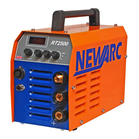
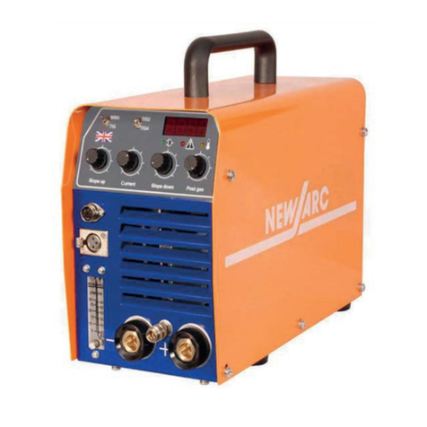
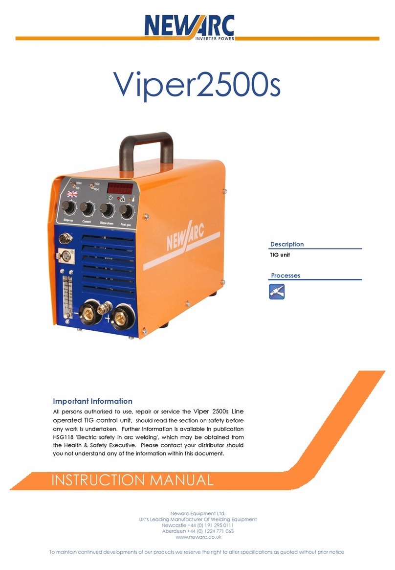
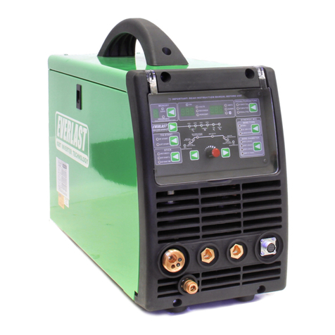
1. On-Off switch
2. Current control
3. Slope up control
4. Arc-force control
5. Digital display
6. Lift/Spark start selector switch
7. Thermal cut-out indicator
8. Power/Gas outlet connector
9. TIG torch switch connector
10. Slope down control
11. Mode switch
12. Remote control socket
13. Negative weld out connector.
4.2 Description of controls
1 On-Off switch
Switches the machine on and off. Upon switching on the
overload indicator will light and the machines output will be
inhibited, after 15 seconds the overload indicator will extin-
guish and the machine is ready for use.
Note: Post gas time. For a 5 seconds period after switching
on the post gas value is displayed as P# (The # value is the
set post-gas time) with the possibility to change the post-gas
time by repeatedly pressing the torch switch button. Every
torch switch press the post gas time is incremented by 1
second (from 0-30 seconds).
This setting is saved therefore it does not need re-setting
each time the machine is switched on.
2 Current control
Use this to set the output current of the RT2000.
3 Slope up control
With the slope up control set to minimum the RT2000 will
strike at the current set by the current control. With the slope
up control set to anywhere but minimum the RT2000 will
strike at 5A and then gradually increase the current to the
setting on the current control, the time this takes is deter-
mined by the position of the slope up control.
4 Arc-force control
Operates in MMA mode only. This control alters the welding
dynamics of the machine to facilitate welding with different
types of welding electrodes (e.g. general purpose, celulosic,
low hydrogen and iron powder). Turning towards maximum
will increase penetration at the expense of increased weld-
ing splatter, turning towards minimum will reduce penetra-
tion but the arc will be smoother and less fierce.
5 Digital display
Gives an accurate indication of the welding current.
Displays HU (High voltage) when HF spark start is activated.
Display the set value of post-gas P#. The display also displays
the setting values of slope up & slope down when been ad-
justed.
6 Lift/Spark start selector switch
Switches the machine into either 'HF start' or 'lift TIG' opera-
tion. In HF start the arc is initiated by a high voltage spark at
the Tungsten's tip. In lift TIG touch the Tungsten to the work-
piece, press the torch switch then lift the Tungsten to the
welding position, the arc will initiate.
7 Thermal cut-out indicator
Indicates that the thermal cut-out in the machine has oper-
ated. (see paragraph 5.1 in the fault finding and mainte-
nance section for possible reasons).
8 Power/Gas outlet connector.
For connection of a TIG torch with a combined power and
gas lead. If a TIG torch with a separate power lead and gas
hose is used, an adapter must be used to connect to this
outlet.
9 TIG torch switch connector.
For connecting the TIG torch switch lead.
10 Slope down control.
With the slope down control set to minimum the current will
shut down immediately the torch switch is released.
With the slope down control set to anywhere but minimum
and the torch switch released, the current will gradually de-
crease from the setting on the current control to 5 amps,
whereby the current will extinguish, the time this takes is de-
termined by the position of the slope down control.
11 Mode switch
This control switches the RT2000's welding mode.
MMA sets the machine in MMA mode.
TIG 2s sets the machine in 'normal' TIG mode, whereby press-
ing the TIG torch switch initiates the arc and releasing it will
extinguish the arc (at the end of any slope down period set).
TIG 4s sets the machine in 'latch' TIG mode, whereby pressing
the torch switch and releasing it initiates the arc, pressing and
releasing it again will extinguish the arc (at the end of any
slope down period set).
Note: Post gas time. When switching from MMA to TIG modes
For a 5 seconds period after switching modes the post gas
value is displayed as P# (The # value is the set post-gas time)
with the possibility to change the post-gas time by repeatedly
pressing the torch switch button. Every torch switch press the
post gas time is incremented by 1 second (from 0-30 sec-
onds).
This setting is saved therefore it does not need re-setting each
time the machine is switched on.
12 Remote control socket
For connecting external remote control units, these are the
RC300 remote control, the RPC300 pulse unit and the RFP300
foot pedal. There is no switch for remote operation, plugging
an external unit into the socket automatically selects remote
operation and disables the internal current control.
13 Negative weld out connector.
Main welding power output connector, negative polarity.
14 Positive weld out connector
1. On-O switch
output will be inhibited, after 15 seconds the overload indicator will extinguish and the machine ready for use.
seconds). This setting is saved therefore it does not need re-setting each time the machine is switched on.
2. Current control
Use this to set the output current of the RT2000.
3. Slope up control
With the slope up control set to minimum the RT2000 will strike at the current set by the current control. With
up control.

