EMIS META 215 User manual

www.emis-meter.com
EMIS-META
215.00.00.OM
version
11.11.2021
v.1.3.05
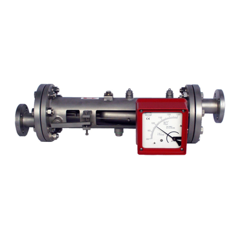
METAL ROTAMETER
EMIS-META 215
Operation manual
EMIS
Russia, Chelyabinsk

EMIS-META 215
OPERATION MANUAL
https://emis-meter.com/
2
General information
This operation manual contains general technical parameters, directions for usage, transportation and
storage, and other information for accurate operation of EMIS-META 215 rotameters.
EMIS® and EMIS logo are registered trade marks of EMIS CJSC.
HART® is the registered trade mark of HART© FieldCom Group.
EMIS CJSC has the right to update the product and documents without prior notice. For any
information about present Operation Manual or other EMIS equipment please contact your local dealer or
EMIS head office.
Any use of the present manual, partial or full, is prohibited without copyright holder permission.
Attention!
Present Manual EMIS-META 215 can be applied only for EMIS-META 215 rotameters. This document is
not applicable to other equipment of EMIS or other companies.
Attention!
Carefully study this Manual before starting operation. Please make sure that you have carefully read and
learned the present manual before installation, operation or maintenance of the equipment. The above is strictly
required to provide safety operation and equipment efficiency.
Contact your local dealer or our technical service:
tel/fax: +7 (351) 729-99-12, 729-99-13, 729-99-16
e-mail: support@emis-kip.ru

EMIS-META 215
OPERATION MANUAL
https://emis-meter.com/
3
CONTENTS
General information .................................................................................................................................2
1. Description and operation.................................................................................................................4
1.1 Application ................................................................................................................................4
1.2 Structure and Operation Principle.............................................................................................4
1.3 Specification..............................................................................................................................6
1.4 Explosion protection .............................................................................................................. 13
1.5 Marking and sealing............................................................................................................... 14
1.6 Supply scope ......................................................................................................................... 17
1.7 Order sheet............................................................................................................................ 19
2. Intended use.................................................................................................................................. 26
2.1 Selection recommendations .................................................................................................. 26
2.2 Safety requirements............................................................................................................... 30
2.3 Mounting on the pipeline........................................................................................................ 30
2.4 Electrical connection.............................................................................................................. 37
2.5 Operation and maintenance .................................................................................................. 39
2.6 Calibration.............................................................................................................................. 41
3. Transportation and Storage........................................................................................................... 43
3.1 Transportation............................................................................................................................. 43
3.2 Storage........................................................................................................................................ 43
4. Recycling ................................................................................Ошибка! Закладка не определена.
5. List of possible failures .................................................................................................................. 43
5.1 List of possible failures (including critical)................................................................................... 43
5.2 Personell mistakes leading to failure, emergency or accidents.................................................. 43
6. Personell actions in case of accident, critical failure or breakdown .............................................. 44
7. Limit state criteria........................................................................................................................... 44
Appendix A............................................................................................................................................ 45
Appendix B............................................................................................................................................ 57
Appendix C ........................................................................................................................................... 58
Appendix D ........................................................................................................................................... 59
Appendix E...................................................................................Ошибка! Закладка не определена.

EMIS-META 215
OPERATION MANUAL
https://emis-meter.com/
4
1. DESCRIPTION AND OPERATION
1.1 Application
EMIS-META 215 rotameters (hereinafter referred to as rotameters) are designed for measuring of
volume of smoothly changing flow of liquids and gases, including chemically corrosive mediums at fuel and
energy plants and other enterprises. Rotameters equipped with LED display can also calculate and show total
accumulated volume, % of the maximum flow, actual current value at current output.
Rotameters are installed in automatic control, adjustment and operation systems and used at variable
industries, stationary plants and pump stations.
This equipment has the following features:
- broad range of medium temperature;
- remote control of readings;
- application for chemically corrosive mediums.
Rotameters can be used for both safe and explosive environments.
Ex-proof rotameters EMIS-META 215-Ex have explosion protection called "intrinsically safe circuit” of
“i” level under GOST 31610.11-2014 (IEC 60079-11:2014) and ex-proof marking 1Ex ib IIB/IIC T4/T2/T1 Gb X
for explosive gas mediums and Ex ib IIIB/IIIC T100°C/T250°C/T420°C Db X for explosive dust mediums.
Ex-proof rotameters EMIS-META 215-Vn have explosion protection called "ex-proof enclosure” of “d”
level under GOST IEC 60079-1-2013 and ex-proof marking 1Ex d IIB/IIC T4/T2/T1 Gb X for explosive gas
mediums and Ex tb IIIB/IIIC T100°C/T250°C/T420°C Db X for explosive dust mediums.
Rotameters without outputs and LED display belongs to non-electrical equipment and have explosion
protection called "design safety” of “c” level under GOST 31441.5-2011 and ex-proof marking II Gb c
T4/T2/T1 X for explosive gas mediums and III Db c T100°C/T250°C/T420°C X for explosive dust mediums.
Rotameter of K version (oxygen application) has separate sign "Oxygen. Dangerous!". Indicator cover
is painted blue.
1.2 Structure and Operation Principle
Rotameters of general application with vertical installation on the pipeline (see. fig.1.1).

EMIS-META 215
OPERATION MANUAL
https://emis-meter.com/
5
Fig.1.1 - Measuring assembly of standard version rotameter
Rotameter consists of two main assemblies - measuring and indication parts. Indication assembly can
be equipped with current output signal or digital HART for remote control of readings.
Liquid or gas inside the flow tube 7 pushes the float 3 with some force (see fig.1.2 - 1.3). Pushed by
this force the float starts to move along the flow tube. While the area between the float and the tapered tube 8
through which the medium flows increases, the drag force decreases.
At a certain position the drag force and gravity (for version G- the spring force) reaches mechanical
equilibrium and the float stops. The distance that the float passed depends on the flow speed and is submitted
to the display through the electromagnetic device. Indicator hand shows current flow speed, the LED display
shows current flow speed and total flow volume.
Fig.1.2 - Measuring assembly of standard version rotameter

EMIS-META 215
OPERATION MANUAL
https://emis-meter.com/
6
Fig.1.3 - Measuring assembly of standard version rotameter
Table 1.1 - Measuring assembly
NO in fig.
Description
1
Float axis
2
Lower stop
3
Float
4
Damper (for gas rotameters)
5
Upper stop
6
Flanges
7
Flow tube
8
Tapered tube
9
Spring
1.3 Specification
1.3.1 Brief description of technical parameters
Brief description of technical parameters is shown in Table 1.2.
Table 1.2 - Technical parameters of rotameter
Name
Description
Flow tube diameter
15; 25; 40; 50; 80; 100; 150
Tolerance limits
- for accuracy class 1.0.
- for accuracy class 1.5.
- for accuracy class 2.5.
- for accuracy class 4.0.
±1 %
±1.5 %
±2.5 %

EMIS-META 215
OPERATION MANUAL
https://emis-meter.com/
7
Name
Description
±4 %
Absolute pressure of medium, MPa;
0.101-32.0
0.15 - 32.01)
Medium temperature, °С
- standard configuration 100
-high-temperature configuration 250
-high-temperature configuration 420
From -40 to +100ºС
From -80 to +250ºС
From -40 to +420ºС
Max density of
medium
for Dn 15mm
5 MPa-s
for other versions
250 MPa-s
Output signals and indication
- indicator
- current 4-20 mA,
- digital HART™,
- up to 2 limit switches
Input voltage
From 14V to 30V DC
Explosion protection:
EMIS-META 215-Ex
EMIS-META 215-Vn
EMIS-META 215-Gbc2)
1Ex ib IIC T4/T2/T1 Gb X;
Ex ib IIIC T100°C/T250°C/T420°C Db X.
1Ex d IIC T4/T2/T1 Gb X;
Ex tb IIIC T100°C/T250°C/T420°C Db X.
II Gb c T4/T2/T1 X;
III Db c T100°C/T250°C/T420°C X.
Atmospheric pressure
84 to 106.7 kPa
Ambient temperature:
From -60 - +703)
Relative humidity of environment
not more than 98% (under 35º С)
Climate version (under GOST 15150-69)
NF climate, device category 1, but for operation
temperature from -60 up to +70°С under 90±3% humidity,
non-condensing
Category of storage and transportation (under
GOST 15150-69)
Category 4 ( at -60 up to +70°С);
Category 1 if without package
Dust and water protection
IP66, IP67
Magnetic field intensity
less than 250 A/m
Vibration
group V1 under GOST R 52931
group V1 under GOST R 52931
Flow range
water
2,5 to 100000 l/h

EMIS-META 215
OPERATION MANUAL
https://emis-meter.com/
8
Name
Description
gas
0,07 to 3000 cbm/h
Calibration interval
5 years
Average time between failure ATBF
over 100 000 hours
Service life
over 10 years
Dimensions and weight
see Appendix A
Content of precious metals
do not contain
1) - for horizontal version of rotameter;
2) - configuration without output signals and display;
3) - as per order sheet (for this range of operating temperature, display indication before -30ºС);
4) - Upon prior agreement with EMIS engineering service.
Attention!
Table data refers to standard version of rotameter. Customized order is available to provide any special
requirements.
1.3.2 Measuring range
Standard flow ranges under normal conditions for liquid are presented in the table 1.3. Water at 20° C,
density of 1000 kg/cbm is taken as standard medium.
Please contact EMIS engineers if any non-standard version or Dn is required for your special purpose.
Table 1.3 - Standard measurement ranges for volume flow of liquid (water) under normal
conditions
Size
Flow range, m3/h
Flow tube material
H, H2**
FT**
015А
0.0025 to 0.025
-
015B
0.004 to 0.04
0.0025 to 0.025
015C
0.0063 to 0.063
0.004 to 0.04
015D
0.01 to 0.1
0.0063 to 0.063
015E
0.016 to 0.16
0.01 to 0.1
015F
0.025 to 0.25
0.016 to 0.16
015G
0.04 to 0.4
0.025 to 0.25
015H
0.063 to 0.63
0.04 to 0.4

EMIS-META 215
OPERATION MANUAL
https://emis-meter.com/
9
025А
0.1 to 1.0
0.063 to 0.63
025B
0.16 to 1.6
0.1 to 1.0
025C
0.25 to 2.5
0.16 to 1.6
015D
0.4 to 4.0
0.25 to 2.5
040А
0.5 to 5.0
0.4 to 4.0
040B
0.6 to 6.0
0.5 to 5.0
050А
0.63 to 6.3
0.6 to 6.0
050B
1.0 to 10
0.63 to 6.3
050C
1.6 to 16
1.0 to 10
080А
2.5 to 25
1.6 to 16
080B
4.0 to 40
2.5 to 25
100
6.3 to 63
4.0 to 40
150
20 to 100
-
Standard flow ranges under normal conditions for gases are presented in the table 1.4. Oxygen of
1.204 kg/nm3 density at 20°C and 0.1013 Mpa is taken as standard.
Please contact EMIS engineers if any non-standard version or Dn is required for your special purpose.
Table 1.4 - Standard measurement ranges for gas (oxygen) under normal conditions
Size
Flow range, m3/h
Flow tube material H, H2, FT
015А
0.07 to 0.7
015B
0.11 to 1.1
015C
0.18 to 1.8
015D
0.28 to 2.8
015E
0.48 to 4.8
015F
0.7 to 7.0
015G
1.0 to 10
015H
1.6 to 16
025А
3.0 to 30
025B
4.5 to 45
025C
7.0 to 70
015D
11 to 110

EMIS-META 215
OPERATION MANUAL
https://emis-meter.com/
10
040А
12 to 120
040B
16 to 160
050А
18 to 180
050B
25 to 250
050В
40 to 400
080А
60 to 600
080B
80 to 800
100
100 to 1000
150
600 to 3000
1.3.3 Accuracy
Accuracy limits are presented below:
± 1,0 % for 1,0 accuracy class;
± 1,5 % for 1,5 accuracy class;
± 2,5 % for 2,5 accuracy class;
± 4.0 % for 4.0 accuracy class.
Accuracy class shall be stated when placing the order (see clause 1.7 of the Order sheet)
1.3.4 Output signals
Rotameters have the following output signals:
indicator;
LED display (optionally)
analog current signal (optionally);
digital HART™ (optionally);
up to 2 limit switches (optionally; if no output signal and LED display are installed).
1.3.4.1 Analog current output signal
Current in the range of 4 to 20 mA has linear dependence with flow volume. Current of 4mA is taken
as "zero" flow. Current of 20mA is taken as upper limit of range.
Parameters of current signal are shown in the Table 1.5.
Table 1.5 - Output current signal parameters
Analog current signal
Range limits, mA
4..20
Load resistance, Ohm
not more than 750
Power supply voltage, V
14 to 30
Nominal output, W
Less than 1
1.3.4.2 Digital signal

EMIS-META 215
OPERATION MANUAL
https://emis-meter.com/
11
Digital signal transmits data by frequency modulation at 4-20 mA output under Bell 202 standard.
HART™ protocol version 5
Rotameter can be connected as point-to-point or multislot.
In point-to-point it is directly connected to master device.
In multislot it is connected to common bus along with other slave devices (up to 15 devices). Only
digital connection is available and current is set as 4 mA.
The following parameters transmitted with digital signal:
rotameter serial number;
total volume
current flow
network address
All HART™ commands are listed in the Appendix F.
1.3.4.3 Indicator
Built-in indicating arrow shows current flow of measuring medium. Additional LED display can be
installed (see fig.1.4). Displays have 2 lines to show current flow and total volume.
Fig. 1.4 - LED Display
1.3.4.4 Limit switch
Rotameters can be equipped with one or two limit switches.
Fig. 1.5 shows front panel of a rotameter with installed limit switches. When the arrow reaches the
upper (1) or lower (2) limit switch activates. Limit switch signals can be used for light/sound alarm or other
purposes.
Loosen the screw to move the limit switch to another position, then tighten it again to fix it.
Table 1.6 - technical parameters of limit switches
Name
Description
Function
Open contact
Commutation voltage, V DC
1... 30
Commutation frequency, Hz, not higher than
500
Commutation current I, mA
0... 100
Idling current I, mA
≤ 15

EMIS-META 215
OPERATION MANUAL
https://emis-meter.com/
12
Fig. 1.5 - Limit switches
Hysteresis of limit switch is rated as ±10% from the specified set-up value.
Attention!
Version with limit switch can be manufactured if no output signal and LED display are installed.
1.3.5 Used materials
Materials used in rotameter construction are listed in table 1.7
Table 1.7 - Materials of rotameter parts and elements
Details and assemble units
Material
Indication unit body and lid
Aluminum alloy
Flanges
stainless steel 304 (12Х18Н10Т) (application Н)
stainless steel 316 (08Х17Н13М2) (application Н2)
Flow tube
stainless steel 304 (12Х18Н10Т) (application Н)
stainless steel 316 (08Х17Н13М2) (application Н2)
PTFE-teflon for pressure up to 6,3 MPa, fluorine plastic F46 for pressure
10MPa (application Ft)
Float
stainless steel 304 (12Х18Н10Т), magnet steel (application Н)
stainless steel 316 (08Х17Н13М2), magnet steel (application Н2)
fluorine plastic F46; magnet steel (application Ft)
Flange seal (for socket and
As per order sheet line (for flange version)

EMIS-META 215
OPERATION MANUAL
https://emis-meter.com/
13
Details and assemble units
Material
clamp connections)
silicone rubber (for socket and clamp versions)
Magnet filter
stainless steel 304 (12Х18Н10Т), magnet steel (standard application Н)
Lining: PTFE-teflon (F4/F46); stainless steel 304; magnet steel (application
Ft)
1.4 Explosion protection
Electrical elements of ex-proof transmitter are covered with ex-proof enclosures, which withstand
internal explosion without transferring the ignition to the external gas air environment. The explosion
resistance and explosion protection of the transmitter enclosure comply with the requirements for electrical
equipment of Group IIС subgroup according to GOST IEC 60079-1-2013. The enclosure is tested for
explosion proofness under GOST IEC 60079-1-2013. Ex-proof connections: axial length of the thread and the
number of full turns in the engagement shall comply with the requirement of GOST IEC 60079-1-2013 for IIС
group electrical equipment; Inspection window is sealed inside the metal rim of the casing cover to provide
integrity;
- EMIS-META 215-Ex configurations shall be operated with power supply unit and recorder with
intrinsically safe circuits under GOST 31610.11-2014 (IEC 60079-11:2011) and intrinsic safety parameters
(circuit level and electrical equipment subgroup) complying with operating conditions in hazardous
environment.
Capacity and inductance of circuits are adjusted according to intrinsic safety requirements for
electrical equipment of Group IIС subgroup under GOST 31610.0-2014 (IEC 60079-0:2011).
Circuit redundancy of “ib” level intrinsic circuits is executed according to GOST 31610.11-2014
(IEC 60079-11:2011).
Electric load of intrinsic circuit elements shall not exceed 2/3 of specified values under normal and
emergency operation.
Clearance, leakage path and electrical endurance of isolation comply with GOST 31610.0-2014
(IEC 60079-0:2011).
Protection from flammable dust ignition is provided using “t” type enclosures under GOST
IEC 60079-31-2013 and explosion protection “c” according to GOST 31441.5-2011 (EN13463-5:2003).
Max temperature of surface heating under operating conditions shall not exceed the values specified
in GOST 31610.0-2014 (IEC 60079-0:2011) for specific temperature classes.
Rotameters are executed under general requirements of GOST 31610.0-2014 (IEC 60079-0:2011) for
electrical equipment located in explosive environment. Mechanical rigidity of transmitter casing complies with
GOST 31610.0-2014 (IEC 60079-0:2011) requirements for electrical equipment of group II with high risk of
mechanical damage. Materials provide friction spark protection under GOST
31610.0-2014 (IEC 60079-0:2011).
Table 1.8 - Input parameters of circuits
Parameter
Parameter value
Max input voltage Ui, B
30

EMIS-META 215
OPERATION MANUAL
https://emis-meter.com/
14
Max input current Ii, mA
160
Max input power Pi, W
1
Max input capacity Ci, pF
0.01
Max input inductance Li, µH
0.01
There is a marking sign for explosion-proof rotameters. The plate is shown in the fig.1.6
1.5 Marking and sealing
1.5.1 Marking
Marking is applied on the plate attached to the rotameter body as shown in the fig.1.6. Marks are
shown in the table 1.9.
Fig.1.6 - Name plate of rotameter
Table 1.9 - Marking on the name plate
NO in fig.
Description
1
Manufacturer trade mark
2
Ingress protection
3
Accuracy class
4
Model
5
Medium type
6
Flow range
7
Max pressure of environment (Pmax)

EMIS-META 215
OPERATION MANUAL
https://emis-meter.com/
15
8
Output signal supply
9
Serial number
10
Equipment mark
11
EAC sign
12
Max temperature of medium (Tmax)
13
Ex-proof sign
14
Ex-proof marking
15
Date of manufacturing
16
Manufacturer information
17
Certification authority and certificate number.
Scale of the rotameter contains the following info (see the fig.1.7-1.9, the table 1.10):
Fig. 1.7 - Scale of rotameter without LED display

EMIS-META 215
OPERATION MANUAL
https://emis-meter.com/
16
Fig. 1.8 - Scale of rotameter with LED display
Table 1.10 - Scale signs
NO in fig.
Description
1
Logo
2
Rotameter model
3
Flow tube diameter
4
Accuracy class
5
Scale units
6
LED display*
7
Measuring medium
8
Medium temperature (for gases)
9
Medium pressure (for gases)
10
Density of measuring medium
*Optionally
Attention!
Please make sure that all information applied on the plates conform with your order sheet.

EMIS-META 215
OPERATION MANUAL
https://emis-meter.com/
17
1.5.2 Sealing
Sealing shall be done to avoid unauthorized access to indicator and parameters change.
Rotameter sealing scheme and marking location are presented in the fig.1.9.
Fig.1.9 - Sealing scheme
1.6 Supply scope
The standard supply scope and additional supply kit are shown in the fig.1.10, 1.11 and tables 1.11,
1.12.
Fig.1.10 - Scope of supply
Table 1.11 - Standard supply scope
NO in fig.
Description
1
Rotameter
2
Operation manual
3
Data sheet
4
TR TS certificate 012/2011 on "The safety of equipment in explosion hazardous
environments" with enclosure.
5
TR TS certificate 032/2013 on "The Safety of equipment working under excessive
pressure"*
* –Provided upon request
Sealing place

EMIS-META 215
OPERATION MANUAL
https://emis-meter.com/
18
Fig. 1.11 - Additional supply kit
Table 1.12 - Additional supply kit
No
Description
1
Mounting kit (flanges, gaskets, studs, nuts, washers, clamps)*
2
Mounting sleeve EMIS-META 215-ВТ
3
Filter and/or gas separator EMIS-VECTA
4
Power adapter EMIS-BREEZE
5
Magnet filter
6
HART modem
7
Spare parts kit, tools and accessories. It includes cable glands, flange gaskets and fixing
accessories for flanges mounting. Other accessories can be included according to customer
needs.
8
Other certificates (on demand)
Depends on the type of connection to the pipeline;
** - Additional kit to mount magnet filter.
Attention!
Please follow the steps below after receiving the rotameter:
check package for damages.
check supply kit.
compare rotameter parameters to ones specified in order sheet.
In case of any damages, supply kit or parameters mismatch, make a report.

EMIS-META 215
OPERATION MANUAL
https://emis-meter.com/
19
1.7 Order sheet
EMIS-META 215 Rotameter configurations are shown in the table 1.13. Order sheet completion is
shown below.
EMIS-META 215-
1
2
3
4
5
6
7
8
9
10
11
12
13
14
-
-
-
-
050
A
-
G
-
N
-
F
-
1.6
-
100
-
2.5
-
-
-
A
-
L
-
-
15
16
17
18
19
-
SC
.
MF
-
GOST
-
V
-
-
Data as shown in order sheet: EMIS-META 215-050А-G-N-F-1.6-100-2.5-A-L-SC.MF-GOST-V
Table 1.13 - Rotameter versions
1
Explosion protection
–
n/a
Ex
Intrinsically safe electrical circuit
Equipment for explosive environments:
1Ex ib IIB/IIC T1/T2/T4 Gb X.
For dust hazardous environments:
Ex ib IIIB/IIIC T100°C/T250°C/T420°C Db X.
Vn
Ex-proof enclosure
Marking of explosion protection for explosive gas environments:
1Ex db IIB/IIC T1/T2/T4 Gb X.
Marking of explosion protection for dust hazardous environments:
Ex tb IIIB/IIIC T100°C/T250°C/T420°C Db X.
Gbc*
Structural safety
Marking of explosion protection for explosive gas environments:
II Gb c T1/T2/T4 X.
Marking of explosion protection for dust hazardous environments:
III Db c T100°C/T250°C/T420°C Db X
IP65/IP67.
X
special order
* -configuration without output signals and no display;
2
Rotameter version
–
vertical installation on pipeline (standard)
Г
horizontal installation on pipeline
3
Size
015
Dn = 15 mm
080
Dn = 80 mm
025
Dn = 25 mm
100
Dn = 100 mm
040
Dn = 40 mm
150
Dn = 150 mm
050
Dn = 50 mm
X
special order

EMIS-META 215
OPERATION MANUAL
https://emis-meter.com/
20
4
Flow range*
A
flow range A
F
flow range F
B
flow range B
G
flow range G
C
flow range C
H
flow range H
D
flow range D
Х
customized flow range
E
flow range E
* - Rotameters flow range can be customized, in this case you put X after flow range (see order sheet
example)
5
Medium type*
L
Liquid
G
gas
O
Oxygen
* - initially rotameters are calibrated for standard conditions Standard conditions are as follows:
liquid - water under 20° C, density 1000 kg/cbm
gas - air under 20° C pressure of 0,1013 MPa, density 1,204 kg/cbm.
To measure other medium please specify it in the order sheet.
6
Flow tube material
N
stainless steel (SS304)
N2
stainless steel (SS316)
Ft*
PTFE-teflon **
X
customized flow tube material
* - Ft version is not applicable for horizontally mounted rotameters (application Г);
** - fluorine plastic for application up to 4,0 MPa.
7
Connection type
F
flange connection
S*
socket connection
C*
clamp connection
X
customized (various connection types under GOST, EN, ASME; please specify)
- configurations with connection S and C are not available for rotameters with flow tubes made of Ft. If you
choose S or C connection, add mounting kit MK symbol after the magnet filter.
For example: EMIS-META 215-050А-G-N-F-1.6-100-2.5-A-L-SC.MF-MK
8
Working pressure*
1.6
max pressure - 1,6 MPa
2.5
max pressure - 2,5 MPa
4.0
max pressure - 4,0 MPa
6.3
max pressure - 6,3 MPa
10
max pressure - 10,0 MPa
16
max pressure - 16,0 MPa
25
max pressure - 25,0 MPa
32
max pressure - 32,0 MPa
Table of contents
Other EMIS Measuring Instrument manuals
Popular Measuring Instrument manuals by other brands

Beko
Beko FLM SF53 Installation and operating manual
Michell Instruments
Michell Instruments OptiCal user manual

DeWalt
DeWalt DW0165 user manual
Spectrum Technologies
Spectrum Technologies Field Scout TDR 250 product manual
Milwaukee
Milwaukee L4 CLL Original instructions
Brooks Instrument
Brooks Instrument SLA5800 Series Installation & operation manual
