Unipro UniGo One kit 1 User manual

UniGo One Laptimer
User Guide
WORK IN PROGRESS !!!
RED TEXT MEANS “NOT DONE”
SUBJECT TO CHANGE
24-12-2022

II
PLEASE READ THE SAFETY
INSTRUCTIONS CAREFULLY
• Read the instructions.
• Keep these instructions.
• Follow all instructions.
• Be careful not to drop it on the ground.
• Do not leave it under heavy objects.
• Be careful not to cut the cables with
sharp objects.
• Clean only with a dry cloth.
• Refer all servicing to approved service
personnel.
Important safety instructionsSafety

III
Contents Contents
IMPORTANT SAFETY INSTRUCTIONS II
CONTENTS III
COPYRIGHT AND ACKNOWLEDGMENTS V
SALES AND SERVICE IN DENMARK V
INTERNATIONAL DEALERS V
DESIGN AND PRODUCTION V
ABOUT THIS USER GUIDE V
DISCLAIMER V
COPYRIGHT V
IntroductIon 7
CONTENT OF PACKAGE 7
UNIQUE UNIGO ONE IDEAS 7
EASY TO USE 7
OVERVIEW 8
SPECIFICATIONS 9
EXAMPLES 10
InstallIng the laptImer
11
MOUNTING ON STEERING WHEEL 11
CONNECTING RPM WIRE 12
RUNNING CABLES 13
SPLITTERS 13
WATER TEMPERATURE 14
CYLINDER TEMPERATURE 14
EXHAUST TEMPERATURE 15
QuIck guIde 17
FOUR BUTTONS 17
MENU SYSTEM 17
TURNING UNIGO ON 18
TURNING UNIGO OFF 18
BUILT-IN HELP 18
FIRST SETUP 19
DRIVING 19
ANALYZING 19
TRANSFER WITH USB 20
TRANSFER WITH WI-FI 20
CTRL+ALT+DELETE 20
confIgurIng the
laptImer 21
ENTER SETUP MODE 21
ENTERING TEXT 22
EVENT SETUP 23
EVENT NAME 23
OUTING TYPE 23
TRACK SETUP 23
TRACK DATABASE 23
AUTO TRACK SELECT 23
COUNTRY 23
SELECT TRACK 23
TRACK NAME 24
TRIGGER 24
MAGNET COUNT 24
MAGNET DELAY 24
IR OR LOOP DELAY TIME 24
KART SETUP 24
WHEEL CIRCUMFERENCE 24
TIRE WEAR MENU 24
USE COUNTER NUMBER 24
COUNTER NO. 25
RESET COUNTER 25
KART NAME / TYPE 25
WHEEL MAGNETS 25
NUMBER OF GEARS 25
LEARN GEARS 25
ENGINE SETUP 26
ENGINE TIMERS MENU 26
USE TIMER NUMBER 26
TIMER NO. MENU 26
TIMER NO. 26
RESET TIMER 26
RPM SENSITIVITY 26
RPM FACTOR 26
RPM SHIFT 26
RPM DELTA 27
RPM SHIFT TYPE 27
RPM LIMITER LOG 27
RPM BAR GRAPH MAX 27
DRIVER SETUP 27
NAME 27
NATIONALITY 27
SENSORS SETUP 28
FLEX INPUT 28
SPLITTER # 28
FLEX INPUT VALUE 28
SPLITTER # VALUE 28
FEEDBACK SETUP 28
WARNING LEDS MENU 28
LED BRIGHTNESS 29
LAST LAP DATA 29

IV
Contents Contents
DATA HOLD TIME 30
LAP TIME DISPLAY 30
SPLIT TIME DISPLAY 30
BETTER / WORSE FEEDBACK MENU 30
BETTER / WORSE TRIGGER 30
UNIGO SETUP 31
RUN MODE SCREENS 31
LCD CONTRAST 31
BACKLIGHT BRIGHTNESS 31
BACKLIGHT OFF TIME 31
AUTO TURN OFF TIME 31
SET TIME 31
SET DATE 32
TEMPERATURE UNIT 32
SPEED / DIST. UNIT 32
LANGUAGE 32
RESTORE FACTORY SETTINGS 32
WI-FI SETUP 33
WI-FI MODE 33
POWER MODE 33
WI-FI STATUS 33
CLIENT MENU 33
CLIENT SSID NAME 33
CLIENT IP ADDRESS 33
ACCESS POINT MENU 33
AP SSID NAME 33
WI-FI PASSWORD 33
AP IP ADDRESS 33
CHANNEL 33
SCAN NETWORK 33
DEFAULT WI-FI SETTINGS 33
reference guIde 35
BASIC INFORMATION 35
FOUR BUTTONS 36
2 WAYS TO PRESS BUTTONS 36
TURN UNIGO ON 36
TURN UNIGO OFF 37
BUILT-IN HELP 37
WARNING LEDS 37
SHIFT LIGHT 38
BETTER / WORSE LIGHT 38
LOW BATTERY 38
HOME SCREEN 39
HOME SCREEN 1 39
HOME SCREEN 2 39
HOME SCREEN 3 39
HOME SCREEN 4 39
RUN MODE 40
RUN MODE 1 40
RUN MODE 2 40
RUN MODE 3 41
ANALYZE MODE 41
SESSION SELECT 41
TIME ANALYSIS 41
OVERVIEW 41
LAP AND SPLIT TIMES 42
RUN MODE VIEW 42
LAP TIME GRAPH 42
MIN/MAX ANALYSIS 43
COUNTERS AND TIMERS 43
TIRE WEAR COUNTERS 43
ENGINE TIMERS 43
LAP LENGTH 43
DELETE MENU 44
DELETE MOST RECENT SESSION 44
DELETE >30 DAYS OLD SESSIONS 44
DELETE ALL SESSIONS 44
WI-FI 44
WI-FI ACCESS POINT 45
WI-FI CLIENT MODE 45
UNIMAN GAME 46
SPACE INVADERS GAME 46
INFO UNIGO 46
INFO GPS 47
INFO SENSORS 48
INFO LAMBDA 48
INFO IR BOX 48
LEARN TRACK 49
RPM SENSITIVITY 49
USB MODE 49
FIRMWARE UPDATE 49
troubleshootIng 51
CLEANING 52
SENSORS AND CABLES 52
WINTER STORAGE 52
MAINTENANCE 52
SERVICE 53
GUARANTEE 53
SERVICE AND GUARANTEE 53
Index 54

V
About
Copyright and acknowledgments
SALES AND SERVICE IN
DENMARK
Unipro ApS
Viborg Hovedvej 24
DK-7100 Vejle
Denmark
Tel +45 7585 1182
www.uniprolaptimer.com
www.facebook.com/uniprolaptimer
www.instagram.com/uniprolaptimer
INTERNATIONAL DEALERS
You can nd our International dealers on the
web site:
www.uniprolaptimer.com
DESIGN AND PRODUC-
TION
Designed and manufactured in Denmark by
Unipro ApS.
The UniGo One Laptimer was designed by
Palle Schultz, Denmark:
www.palleschultz.dk
Unipro reserves the right to make changes and
improvements to any of the products described
in this document without prior notice.
Part numbers:
03-05-001 UniGo One kit 1
03-05-002 UniGo One kit 2
03-05-003 UniGo One kit 3
ABOUT THIS USER GUIDE
This guide was written and produced by
Unipro ApS.
UniGo One User Guide version 1.00
Made for UniGo One rmware version 1.0x.xxx
DISCLAIMER
Some of this user guide might contain informa-
tion on future features. It might turn out that
it is not possible to implement these features,
but then they will be removed from this guide.
COPYRIGHT
Copyright © 2022 Unipro ApS

VI
This page was intentionally left blank.

7
This User Guide contains all relevant information about your new
UniGo Laptimer.
Get started with the UniGo in 5 minutes with the Quick Guide.
Read all about the advanced features and functions in the
Reference Guide.
Before you start, please check that your UniGo package contains
the accessories described below.
CONTENT OF PACKAGE
The UniGo package contains the following:
• UniGo One Laptimer.
• RPM wire.
• USB data / charge cable.
• USB power adapter.
• Power socket for your country.
• This User Guide.
• Registration card.
If any of these items are missing please contact
your dealer.
Note: You should retain the packaging in case
you need to transport the unit.
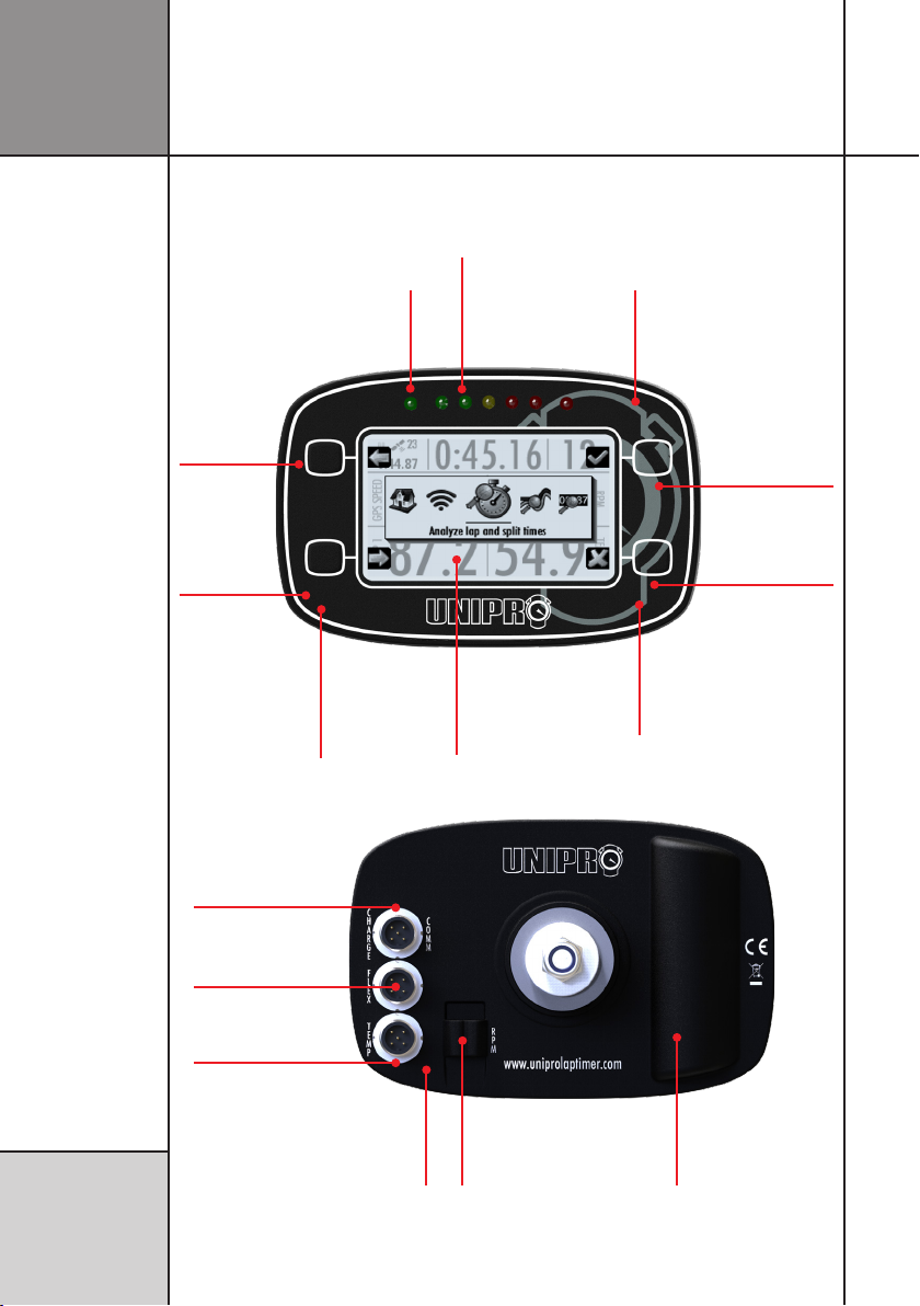
UNIQUE UNIGO ONE
IDEAS
UniGo One combines many new ideas not seen
before in a Unipro Laptimer:
• Big high resolution display with gray
tones. Providing more than 40000 pixels
with 16 gray levels makes text and
graphics easy to read.
• Wi-Fi for fast and easy upload of data to
a PC or Mac.
• Very high brightness, fully programma-
ble warning LEDs. Clearly visible in full
daylight.
• Intuitive user interface with only four
buttons. Help text to explain what each
function does.
• Direct connection of analog/digital
sensors.
• Trig directly from magnet stripes.
• High capacity battery built-in.
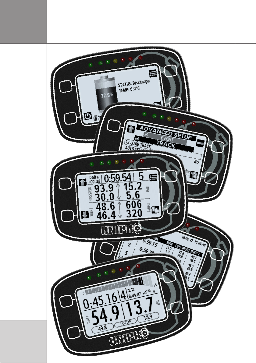
EASY TO USE
Even with all the advanced features, the
Laptimer is very easy to use.
The graphical display makes it effortless to
see and analyze the lap times and data values
saved in the Laptimer. Data analysis can be
done directly on the Laptimer without the need
to transfer the data to a computer.
A unique GPS antenna enables a very thin and
slick design. This antenna design is less sensi-
tive to movement of the antenna, and ensures
a perfect reception of GPS signal all the time.
Several sensors are built in UniGo One, includ-
ing environment temperature, ambient light,
steering wheel position, steering wheel turn
rate, RPM analyzer and magnet receiver.
The built-in Li-Ion battery gives 40 hours of
operation and with the powerful charger, it
can be charge at different speeds, including
Introduction
Introduction

8
OVERLAY
Thick window that
is scratch resistant.
fast charge. The fuel gauge will give precise
information on capacity left in percent, and
even time to empty calculation.
Please note that this user guide is intended for
UniGo One only.
OverviewIntroduction
Wi-Fi
Wireless setup/
data transfer
directly to PC or
router.
UNIGO BOX
Lightweight plastic casing with
sensors connected directly or
through the optional UniBox.
RPM
Wire to the engine
ignition cable. Soft-
ware adjustable.
DISPLAY
Bigger high resolution
display with gray scales
and good contrast. White
backlight.
HEART RATE
Add a heart rate
chest strap and log
it during the race.
HUGE MEMORY
Powerful processors
and huge memory
for future features.
AMBIENT SENSOR
Light sensor to adjust
backlight according to
ambient light.
BETTER/WORSE
Two extra LED lamps
for better / worse
indication.
ACC/GYRO
Built-in accele-
rometer and gyro
for steering wheel
position.
Actual size
1:2
LED LAMPS
5 adjustable high
brightness LED lamps
for warnings and/or
gear shift indicator.
CHARGE / COMM
Charge. USB, external
power and expansion.
FLEX
Trigger, speed, analog,
Lambda, IR box etc.*
TEMP
Thermocouple or PT1000
temperature sensors.*
* Two inputs with
optional cable splitter.
BLE/BT
Easy transfer to
mobile phone
or tablet. BT for
audio headset.
LI-ION BATTERY
High capacity recharge-
able battery gives you
40 hours of use.

9
Specications Introduction
Lap memory Virtual unlimited (4GB)
Log memory Virtual unlimited
Channels logged Lap time, RPM, 2 x temperature, speed, gear, battery voltage, 2 x Flex,
GPS speed, GPS position, environment temp, steering wheel angle,
steering wheel turn rate.
Max. 128 channels with the UniBox expansion box
Resolution 1/10000 sec, 1 mm, 1 RPM, 0.01 °C, 0.01 km/h, 0.01 V
Logging frequency 1 - 60 Hz (programmable)
Sensor inputs RPM, 2 x temperature*, 2 x Flex*, BLE
GPS Built-in. Supports 10Hz from GPS, Glonass, Galileo and Beidou
Trigger GPS, magnet (built-in) or infrared (external)
Split times Magnet or GPS
Communication Wi-Fi (access point or client), BLE, USB, NFC
Real-time-clock Yes (automatically set by GPS)
Power supply Built-in Li-Ion battery. 3400 mAh
External supply 5-17 volt DC. From charger, USB power bank or LiPo battery
Expandable Yes
Display 256 x 160 pixels, 16 gray tones, top view
Backlight Yes, white, automatic light adjustment
LED warnings 7 high-brightness, 5 fully programmable, 2 better / worse indicators
Audio feedback Yes (via Bluetooth headset)
CPU 2 x 32-bit low-power
Data upload USB full-speed with included USB cable, Wi-Fi or BLE
Buttons 4 software dened with icons
Software included Unipro Analyser analyze software. Both Windows and Mac version
Casing Lightweight plastic
Waterproof Yes
Dimensions 136.7 x 89.7 x 18.3 / 30.4 mm (5.38” x 3.53” x 0.72”/1.20”)
Weight 350 g (12.35 ounces)**
* Shared connector: Optional cable splitter needed.
** Weight: Includes Laptimer, RPM cable and ttings.

10
Introduction Examples

11
Installing the Laptimer
Installing the
Laptimer
A good installation is key to get good and reliable operation of
UniGo. Read this installation guide and learn how to:
Install the Laptimer, attach cables and sensors and see how to
mount it all on the go-kart.
You will be ready to go in 20 minutes...
MOUNTING ON STEERING
WHEEL
The rst step of the installation is the mounting
of the Laptimer on the steering wheel.
The Laptimer should be mounted at the top
of the steering wheel to make it easy to read
during driving and to operate it in the pit.
UniGo mounted at the top of the steering
wheel for easy reading and operation.
The Laptimer is mounted using the included
bracket and you need to be carefully to mount
all the hard and soft discs in the right order
to avoid vibrations and to ensure the correct
distance from the steering wheel.
Start the installation with a soft disc.
Finish with a soft disc, hard disc, washer
and the nut.

12
UniGo mounted at the correct distance to
the steering wheel.
Before tightening the nut, make sure that all
the cables can be connected without conict-
ing with the steering wheel or other obstacles.
CONNECTING RPM WIRE
The RPM wire is used to pick up the engine’s
revolution count by sensing the pulses on the
ignition cable going from the ignition coil to
the spark plug.
The ignition is a very noisy signal and extra
care should be paid on installing the RPM
wire.
The wire can be removed from the Laptimer
and attached again if needed. It is simply a
wire going through two holes with a loop.
Run the RPM wire away from other cables.
To make the best possible installation, keep
the RPM wire away from all other cables.
RPM wire attached with cable ties.
The RPM wire needs to run all the way from
the Laptimer to the engine on the back.
Secure the wire all the way with cable ties.
The RPM wire is running alone all the way
to the ignition.
RPM wire mounted to pick up the ignition
signal from the ignition wire.
The RPM wire is attached to the ignition cable
in a way that gives a good pick up of the sig-
nal. Twist the wire around the cable and make
a loop at the end like shown on the picture.
Installation
Installing the
Laptimer

13
RUNNING CABLES
The installation of the Laptimer should be seen
as a permanent installation on the go-kart and
the time to run the cable in a nice way is time
well spend.
Cable xed to frame. Run RPM wire sepa-
rately.
Use plenty of cable ties and make sure to use
nice soft bends on the cable. When tightening
the cable ties, make sure not to tightening
them too hard to avoid squeeze the cable.
Cable xed to the frame with cable ties.
Running the cables from the Laptimer on the
steering wheel is the biggest challenge. The
cable need to be mounted in a way that the
steering wheel can be moved freely.
Cable xed to the frame with cable ties.
Attach the cables together with a cable tie
and attach the bundle to the steering column.
Make a soft bend with a suitable length and
check the steering wheel have total freedom
in turning. The cables should not pull at the
connectors when turning and no sharp bend
should be allowed.
Professional installation will ensure profes-
sional results.
SPLITTERS
Cable splitters are used to increase the
number of sensor that can be connected to the
Laptimer.
Installing the
Laptimer
Installation

14
Gray splitter for temperature and black for
receiver and speed.
Two splitters mounted to increase number
of sensors.
Two different cable splitters are used. A gray
version is used for temperature and a black
version for everything else.
The splitters reduce the number of cables to
the steering wheel.
The splitters reduces the number of cables to
the steering wheel and is part of the perma-
nently installation. Make sure that splitters are
securely fasten to the frame.
WATER TEMPERATURE
The water temperature sensor is typically
mounted in the T-junction that goes into the
cooling water hose. First mount the sensor in
the T-junction and then mount the T-junction
the hole. Make sure the hose is waterproof by
tightening the clamps.
T-junction mounted in the cooling water
hose with a temperature sensor.
CYLINDER TEMPERATURE
The cylinder head temperature is measured just
below the spark plug. The cylinder temperature
sensor is available in two different sizes and it
is important to order the right one.
Sensor mounted instead of the washer on
the spark plug.
Installing the
Laptimer Installation

15
Cylinder head temperature sensor mounted
below the spark plug.
Before mounting the cylinder sensor, remove
the washer from the spark plug.
EXHAUST TEMPERATURE
The exhaust sensor is mounted in the exhaust
pipe. The tting for the exhaust sensor is
welded to the exhaust 12 cm (4.7 inch) from
the backside of the piston. That way the sensor
measures the temperature of the gas and not
the ames.
Start by welding the exhaust tting to the
exhaust pipe and then drill a ø4.5 mm hole
through the tting for the sensor.
Always check if local regulation might
prevent you from using an exhaust tem-
perature sensor in the race.
Drill a ø4.5 mm hole for the sensor through
the exhaust tting.
Exhaust tting welded on the exhaust pipe.
Place the exhaust sensor in the tting and
fasten the nut. Do not tightening it too much.
Installing the
Laptimer
Installation

16
Exhaust sensor mounted with a big soft
bend on the cable.
Make sure the cable is not touching the ex-
haust pipe and make a soft bend on the cable
like shown on the picture.
Installing the
Laptimer Installation

17
Quick Guide
FOUR BUTTONS
For easy operation we made four software
programmable buttons on UniGo One. If the
button have any function, it will clearly be
shown with a small icon next to the button.
Icons use less space than text and it should be
obvious what each button does. But here are
some examples:
Brings up the rolling menu.
Change to run mode.
Change to the last analyze screen.
Edit the current selected preference.
The buttons are either roll-out or xed buttons.
If we have space enough on the screen,
they will be xed, but if there are a lot of
information on the screen, they will roll-out on
the screen when needed. The top right button
is almost always a menu button. The three
other buttons might have a specic function
depending on what screen you are on.
If it is roll-out buttons, they will roll in again
after a few seconds. This is to give you the full
screen again for information.
MENU SYSTEM
The typically way of doing an user interface is
with menus and then navigate between them
and select what you want. But with only four
buttons this gets complicated so we designed
a brand new user interface without the classic
menus!
It is important to understand the thoughts
behind it.
Instead of the traditional menus, you will nd
an popup icon list. This list is dynamic, and the
content depends on where you are. We call
this the rolling menu.
Rolling menu when activated from the min/
max analyze screen.
The icon list shows 5 icons directly. The one in
the center is priority number 1, meaning it is
most likely the one function you need. To the
right and left for the center icon, you will nd
priority 2 and 3, and the next two icons are
priority 4 and 5. You will then be able to scroll
the list to get priority 6 and up. It does not
matter if you scroll right or left. You will nd
Read the Quick Guide and learn how to use the basic functions
of the UniGo One:
Turn UniGo One on and off, start logging data, analyze them on
UniGo One and transfer them to a computer with the included
USB cable or Wi-Fi.
You will be ready to go in 5 minutes...
Quick Guide
17

18
Quick guideQuick Guide
the same icons in the list. At the end if the list
you will get back to the rst 5 icons.
This way you do not need to navigate through
several menus, but can jump directly to what
you want. Some icons will be direct functions,
and others will change the icon list to give you
more choices.
The center icon will be enlarge and a help text
is shown below it. This way it should be easy
to learn the icons. We use a common way of
combining icons into one.
Analyze
Setup
Information
Select
The combination can then be like this:
Information about GPS satellites.
Analyze lap times.
TURNING UNIGO ON
There are 4 different ways to turn UniGo on:
1. Press one of the two buttons on the right
shortly to start the Laptimer manually.
2. Start the engine and UniGo will start when
it detects the RPM signal.
3. Connect the USB / charger cable into a
charger or computer.
4. Start the engine if the RPM wires is connect-
ed to a UniBox.
UniGo start by turning on the backlight at
25% and show a Unipro splash screen. This is
showing as fast as it is possible, and it will stay
there until UniGo is fully booted.
After booting up, UniGo starts by showing the
startup screen including information about
rmware version number, serial number,
battery capacity, the environment temperature,
GPS satellites xed, and the time of day. If
the driver’s name is entered, it will show that
below the Unipro logo.
Startup screen with information about
rmware version and serial number
TURNING UNIGO OFF
There are different ways to turn UniGo off.
Press the top right button and hold it down to
turn UniGo off. When you see “TURN OFF” in
the display, you can release the button again.
Power off screen when UniGo is turning off.
UniGo will also turn itself off if no button
is pressed and no RPM, speed or trigger is
detected after a preselected time. Please see
”AUTO POWER OFF TIME” on page 31.
You can also turn it off from the rolling menu
by pressing the icon.
BUILT-IN HELP
When you move around in menus, UniGo will
display one line of help text at the bottom of
the display. Use this line to get familiar with
the different settings in UniGo.

19
Quick Guide
Quick guide
Example on the help text describing the
current selection.
FIRST SETUP
When UniGo starts for the rst time it will
show the setup screen shown below. This
contains essential setup of the most important
settings. It included settings like user interface
language, country you are driving in and what
type of units to use.
First setup. Essential settings needed to get
started with UniGo One.
Please set “AUTO TRACK SELECT” to Yes
and then select the country you are in.
To read more information about the rst setup
settings, please look in the “Conguring the
Laptimer” chapter.
DRIVING
When UniGo detects a RPM signal from the
engine, it will automatically go to run mode.
It will automatically start to log all data from
sensors and measure lap and split times.
Typically run mode 1 when driving.
There is not much you can do in run mode ex-
cept concentrating on driving! You will be able
to change between three predened layouts
by pressing the mode button ( ). This will
toggle through the different run modes. UniGo
will remember the one you prefer and it will
start in the same mode as the last time.
• Run mode 1 is for four data elds.
• Run mode 2 is for gear karts with two
data elds and last lap data.
• Run mode 3 is for two data elds with
best lap information and last lap data.
ANALYZING
When analyzing you will typically start with the
overview screen. This screen will give you the
quick overview of the three best laps with the
minimum and maximum values for the most
important sensors.
Quick overview of three best laps in analyze
mode.
You can toggle around different analyze
screens by pressing the mode button ( ).
Another important screen is the lap and split
times screen.

20
Overview of split and lap times.
You can scroll the screen by using the up ( )
and down ( ) buttons.
TRANSFER WITH USB
It is very easy to transfer data to the Unipro
Analyser program. Just insert the included
USB/charge cable in the top connector (named
COMM).
USB mode when connected to a computer.
When the cable is attached, UniGo cannot be
operated because the computer use the Flash
drive. The Unipro Analyser program can then
transfer the data les.
Like any other Flash drive you need to
eject the drive safely before removing
the cable from the computer.
TRANSFER WITH WI-FI
We would always recommend to use Wi-Fi for
data transfer instead of USB cable.
Wi-Fi screen when not connected..
You can toggle around different analyze
screens by pressing the connect button ( ).
Another important screen is the lap and split
times screen.
CTRL+ALT+DELETE
Because the battery is inside UniGo One and
the box is sealed, there is no way of ”power cy-
cling” if something goes wrong. We therefore
had to build in a reset function also known
from a computer like ctrl + alt + delete.
On UniGo One, you just press the two right
buttons and keep pressing them until UniGo
restarts. It takes around 10 seconds.
Even though this is a complete reset, you will
not lose data or settings.
That’s how easy it is! If you are ready for
some more advanced features, then read the
Reference Guide later in this manual.
Also check www.uniprolaptimer.com for
news and updates.
Quick guideQuick Guide
This manual suits for next models
5
Table of contents
Other Unipro Measuring Instrument manuals