EML Kalyx-RG User manual
UM-975-001-WSD1 Manual –V2.1
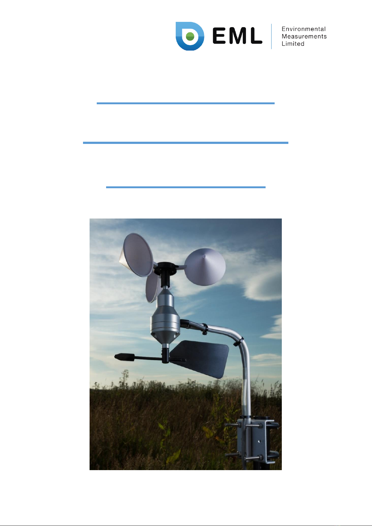
Wind Speed &
Direction Sensor
User Manual

UM-975-001-WSD1 Manual –V2.1 2 | P a g e
PUBLISHED BY
Environmental Measurements Limited (EML)
7 Jupiter Court
Orion Business Park
North Shields NE29 7SE
United Kingdom
Visit our internet pages at http://www.emltd.net
©EML 2017
No part of this manual may be reproduced without any form or by any means, electronic or
mechanical (including photocopying), nor may its contents be communicated to a third party
without prior written permission of the copyright holder.
The contents are subject to change without prior notice.
Please observe that this manual does not create any legally binding obligation for EML
towards the customer or end user. All legally binding commitments and agreements are
included exclusively in the applicable supply contract or Conditions of Sale.

UM-975-001-WSD1 Manual –V2.1 3 | P a g e
Table of Contents
List of Figures ..........................................................................................................................................4
List of Tables ...........................................................................................................................................4
1. General Information.......................................................................................................................5
About this Manual ..............................................................................................................................5
Version Information........................................................................................................................5
Related Manuals .............................................................................................................................5
2. Introduction....................................................................................................................................6
3. Site and Installation Requirements ...............................................................................................6
Choosing a site....................................................................................................................................6
4. Wiring & connection information..................................................................................................7
Wiring colours.....................................................................................................................................7
5. Additional Technical information..................................................................................................8
Technical Specifications of the WSD1.................................................................................................8
Speed component of the sensor (anemometer) ................................................................................9
Direction component of the sensor (vane).........................................................................................9
General Cable information..................................................................................................................9
Long cable runs on the sensor ............................................................................................................9
Wind direction averaging....................................................................................................................9
6. Assembly and use of the WSS1....................................................................................................10
Basic assembly ..................................................................................................................................10
Lower mast assembly........................................................................................................................10
Upper mast assembly........................................................................................................................10
Final assembly...................................................................................................................................12
Alignment..........................................................................................................................................12
7. Assembly and use of the WSS2....................................................................................................15
Unpacking and Assembly..................................................................................................................15
Fitting to a mast................................................................................................................................15
Alignment..........................................................................................................................................15
Appendix A –Wind sensor products and spares.................................................................................17

UM-975-001-WSD1 Manual –V2.1 4 | P a g e
List of Figures
Figure 1 - Wiring diagram of WSD1.........................................................................................................7
Figure 2 - Mast assembly detail ............................................................................................................11
Figure 3 - Guy wiring detail...................................................................................................................13
Figure 4 - Assembled WSS1...................................................................................................................14
Figure 5 - Assembled WSS2 kit..............................................................................................................16
List of Tables
Table 1 - Document Revisions.................................................................................................................5
Table 2 - Related Manuals ......................................................................................................................5
Table 3 - Wiring details ...........................................................................................................................7
Table 4 - Contents list of WSS1 kit. .......................................................................................................10
Table 5 - Contents list of WSS2.............................................................................................................15
Table 6 –Wind sensors products..........................................................................................................17
Table 7 –Wind sensor spare parts........................................................................................................17

UM-975-001-WSD1 Manual –V2.1 5 | P a g e
1. General Information
About this Manual
This manual is intended as a general guide for installing, wiring and using a Kalyx-RG rain gauge. The
information contained in this manual may not cover all aspects of Kalyx-RG applications. Please refer
to associated equipment manuals or consult papers and technical notes on the EML website
(www.emltd.net).
Version Information
Table 1 - Document Revisions
EML Document Number:
Description:
UM-975-001
Version 1.0 –First Release, dated 19th August 2015
Version 2.0 –Second Release, dated 1st March 2018
Version 2.1 –Third Release, dated 13th March 2019
Related Manuals
Table 2 - Related Manuals
EML Document Number:
Description:
Table of contents
Other EML Accessories manuals


