manuals.online logo
Brands
  1. Home
  2. •
  3. Brands
  4. •
  5. emmeti
  6. •
  7. Plumbing Product
  8. •
  9. emmeti KEV 2 07514110 Guide

emmeti KEV 2 07514110 Guide

This manual suits for next models

2

Other emmeti Plumbing Product manuals

emmeti Gerpex Press Fit Installation and operation manual

emmeti

emmeti Gerpex Press Fit Installation and operation manual

Popular Plumbing Product manuals by other brands

Weka 506.2020.00E ASSEMBLY, USER AND MAINTENANCE INSTRUCTIONS

Weka

Weka 506.2020.00E ASSEMBLY, USER AND MAINTENANCE INSTRUCTIONS

American Standard DetectLink 6072121 manual

American Standard

American Standard DetectLink 6072121 manual

Kohler K-6228 Installation and care guide

Kohler

Kohler K-6228 Installation and care guide

Uponor Contec TS Mounting instructions

Uponor

Uponor Contec TS Mounting instructions

Pfister Selia 49-SL Quick installation guide

Pfister

Pfister Selia 49-SL Quick installation guide

Fortis VITRINA 6068700 quick start guide

Fortis

Fortis VITRINA 6068700 quick start guide

Kohler K-12183 Homeowner's guide

Kohler

Kohler K-12183 Homeowner's guide

Maxxus MX-M206-01 instruction manual

Maxxus

Maxxus MX-M206-01 instruction manual

Viega Prevista Pure 8512 Instructions for use

Viega

Viega Prevista Pure 8512 Instructions for use

Kohler Centerset K-15240 Homeowner's guide

Kohler

Kohler Centerset K-15240 Homeowner's guide

Viega Prevista Dry 8522.33 Instructions for use

Viega

Viega Prevista Dry 8522.33 Instructions for use

Sanela Lema SLP 59RB Instructions for use

Sanela

Sanela Lema SLP 59RB Instructions for use

Elkay EDF15AC Installation, care & use manual

Elkay

Elkay EDF15AC Installation, care & use manual

Hans Grohe AXOR Citterio E 36702000 Instructions for use/assembly instructions

Hans Grohe

Hans Grohe AXOR Citterio E 36702000 Instructions for use/assembly instructions

baliv WT-140 manual

baliv

baliv WT-140 manual

Kohler Mira Eco Installation & user guide

Kohler

Kohler Mira Eco Installation & user guide

BELLOSTA romina 0308/CC Installation instruction

BELLOSTA

BELLOSTA romina 0308/CC Installation instruction

Bristan PS2 BAS C D2 Installation instructions & user guide

Bristan

Bristan PS2 BAS C D2 Installation instructions & user guide

manuals.online logo
manuals.online logoBrands
  • About & Mission
  • Contact us
  • Privacy Policy
  • Terms and Conditions

Copyright 2025 Manuals.Online. All Rights Reserved.

MANUALE INSTALLAZIONE ED USOMANUALE INSTALLAZIONE ED USO
INSTALLATION AND USE MANUALINSTALLATION AND USE MANUAL
MANUAL DE INSTALACION Y USOMANUAL DE INSTALACION Y USO
MONTAGEA-UND GEBRAUCHS ANLEITUNGENMONTAGEA-UND GEBRAUCHS ANLEITUNGEN
MANUEL D’INSTALLATION ET D’UTILISATIONMANUEL D’INSTALLATION ET D’UTILISATION
OUT
IN
2
Installazione / Installation / Instalación / Installation / Installation
IT
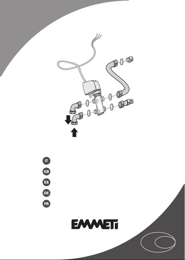
Montaggio valvola a 3 vie con 4 attacchi (3/4" M-3/4" M)
GB
Installation 3 way valve + copper pipes valve / System kit (on the main coil)
ES
Montaje de la válvula de tres vías con cuatro conexiones
(3/4" M-3/4" M)
DE
Montage 3-Wege-Ventil mit 4 Anschlüssen (3/4" M-3/4" M)
FR
Montage de la vanne à trois voies avec 4 raccords (3/4" M-3/4" M)
Mod. KEV 2 07514110 - 07514112 - 07514114
Emmeti S.p.a vi ringrazia per la fiducia concessaci
nell’acquisto di questo prodotto. Vi invitiamo a leggere
attentamente questo manuale dove sono riportate le
caratteristiche tecniche e tutte le informazioni utili
per ottenere un corretto funzionamento. I dati possono
subire modifiche ritenute necessarie per il migliora-
mento del prodotto.
Wir danken Ihnen für das Vertrauen, das Sie unserem
Unternehmen durch den Kauf Dieser Artikel. Bitte
lesen Sie das vorliegende Handbuch vor der ersten
Inbetriebnahme des Gerätes aufmerksam durch und
bewahren Sie dieses in dessen unmittelbarer Nähe.
Die in dieser Veröffentlichung enthaltenen Daten
können aus technischen und/oder kommerziellen
Anforderungen ohne Voranzeige in jedem beliebigen
Momemt abgeändert werden.
Emmeti S.p.a. thank you for your choice this product.
Carefully read this manual which contains the specifi-
cations and all useful information for correct operation
this product. Further improvements on product, may
introduce, without prior notice, changes of contents
herein.
Nous vous remercions de la confiance que vous nous
avez accordée en acquérant produit.
Nous vous invitons à lire attentivement ce manuel
dans lequel figurent toutes les caractéristiques tech-
niques et toutes les informations nécessaires pour le
bon fonctionnement.
Les données contenues dans le manuel peuvent faire
l’objet de modifications jugées nécessaires en vue de
l’amélioration du produit.
Emmeti S.p.a. agradecemos la confianza que nos ha
otorgado al comprar este producto. Le invitamos a leer
atentamente este manual donde le explicamos las
características técnicas y toda la información necesa-
ria para obtener un funcionamiento correcto.
El continuo desarrollo para el mejoramiento del pro-
ducto, puede comportar, sin necesidad de preaviso,
modificaciones o cambios a en lo descrito.
3
Installazione / Installation / Instalación / Installation / Installation
ITIT GBGB ESES DEDE FRFR
IT
COMPONENTI FORNITI mod. KEV2
A. N° 1 valvola a 3 vie con 4 attacchi (3/4" M - 3/4" M)
B. N° 1 servocomando elettrotermico
C. N° 1 Nipples filettato (1/2" M - 1/2" M)
D. N° 1 guarnizione (1/2")
E. N° 1 Tubo rame ad “S”, Ø 14 mm (1/2" F - 3/4" F)
F. N° 1 Tubo rame dritto, Ø 14 mm (1/2" M - 3/4" F)
G. N° 4 guarnizioni (3/4")
H. N° 2 tubi rame 90°, Ø 14 mm (1/2" F - 3/4" F)
I. N° 2 morsetti “Mamut” + 1 vite
GB
SUPPLIED ITEMS mod. KEV2
A. N° 1 3-way valve with 4 connections (3/4" M - 3/4" M)
B. N° 1 electrothermic actuator
C. N° 1 Thread nipple (1/2" M - 1/2" M)
D. N° 1 Sealing (1/2")
E. N° 1 “S” copper pipe, Ø 14 mm (1/2" F - 3/4" F)
F. N° 1 straight copper pipe, Ø 14 mm (1/2" M - 3/4" F)
G. N° 4 Sealings (3/4")
H. N° 2 90° copper pipes, Ø 14 mm (1/2" F - 3/4" F)
I. N° 2 “Mammoth” terminals + 1 screw
ES
COMPONENTES SUMINISTRADOS mod. KEV2
A. Una válvula de tres vías con cuatro conexiones (3/4" M-3/4" M)
B. Un servomando electrotérmico
C. Un niple roscado (1/2" M - 1/2" M)
D. Una junta (1/2")
E. Un tubo de cobre en “S”, Ø 14 mm (1/2" H - 3/4" H)
F. Un tubo de cobre recto, Ø 14 mm (1/2" M - 3/4" H)
G. Cuatro juntas (3/4")
H. Dos tubos de cobre de 90°, Ø 14 mm (1/2" H - 3/4" H)
I. Dos borneras "Mamut" + Un tornillo
4
Installazione / Installation / Instalación / Installation / Installation
ITIT GBGB ESES DEDE FRFR
Installazione / Installation / Instalación / Installation / Installation
DE
BEILIEGENDE BAUTEILE Mod. KEV2
A. Anz.1 3-Wege-Ventil mit 4 Anschlüssen (3/4" Außengewinde - 3/4" Außengewinde)
B. Anz.1Elektrothermische Servosteuerung
C. Anz. 1 Gewindenippel (1/2" Außengewinde- 1/2" Außengewinde)
D. Anz. 1 Dichtung (1/2")
E.
Anz. 1 Kupferrohr “S”-Form, Ø 14 mm (1/2" Innengewinde - 3/4" Innengewinde)
F.
Anzahl 1 Kupferrohr gerade, Ø 14 mm (1/2" Außengewinde - 3/4" Innengewinde)
G. Anz. 4 Dichtungen (3/4")
H. Anz. 2 Kupferrohre 90°, Ø 14 mm (1/2" Innengewinde - 3/4" Innengewinde)
I. Anz. 2 Klemmen “Mamut” + 1 Schraube
FR
COMPOSANTS FOURNIS mod. KEV2
A. 1 vanne à trois voies avec 4 raccords (3/4" M - 3/4" M)
B. 1 servocommande électrothermique
C. 1 Mamelon fileté (1/2" M - 1/2" M)
D. 1 joint (1/2")
E. 1 Tuyau cuivre en “S”, Ø 14 mm (1/2" F - 3/4" F)
F. 1 Tuyau en cuivre linéaire, Ø 14 mm (1/2" M - 3/4" F)
G. 4 joints (3/4")
H. 2 tuyaux cuivre à 90°, Ø 14 mm (1/2" F - 3/4" F)
I. 2 bornes “Mammouth” + 1 vis
Posizione attacchi idraulici (ad installazione ultimata) / Water connections
position (When the installation is finished) / Posición de las conexiones
hidráulicas (con la instalación acabada) / Position der Wasseranschlüsse
(nach beendeter Montage) / Position des raccords hydrauliques (à installa-
tion terminée)
Riferimento / Ref. / Ref. / Ref. / Réf. 1 OUT 2 IN
Xmm 105 mm 155 mm
Ymm 215 mm 205 mm
Zmm 120 mm 95 mm
Attacchi / Connectors / Conexiones / Anschlüsse / Raccords / Ø
1/2" F 1/2 " F
Installazione / Installation / Instalación / Installation / Installation
5
Installazione / Installation / Instalación / Installation / Installation
ITIT GBGB ESES DEDE FRFR
X
0
Z
Y
F
G
H
E
D
C
B A
1
H
OUT
IN
2
I
Pressione di esercizio MAX 1000 Kpa / Working pressure MAX 1000 Kpa/
Presión de funcionamiento máx. 1.000 kPa/ MAX. Betriebsdruck 1000 Kpa /
Pression de fonctionnement MAX 1000 Kpa/
IN
OUT
6
Installazione / Installation / Instalación / Installation / Installation
ITIT GBGB ESES DEDE FRFR
Installazione / Installation / Instalación / Installation / Installation
Tabella varianti / Table of variants / Cuadro de variantes / Tabelle Varianten
IT
KVS 2,5
Servocomando elettrotermico
230 V cod. 07514110
KVS 2,5 24 V cod. 07514112
KVS 3,7 230 V cod. 07514114
GB
KVS 2,5
Servocontrol electrothermal
230 V cod. 07514110
KVS 2,5 24 V cod. 07514112
KVS 3,7 230 V cod. 07514114
ES
KVS 2,5
Servomando electrotérmico
230 V cod. 07514110
KVS 2,5 24 V cod. 07514112
KVS 3,7 230 V cod. 07514114
DE
KVS 2,5
Elektrothermische Servosteuerung
230 V cod. 07514110
KVS 2,5 24 V cod. 07514112
KVS 3,7 230 V cod. 07514114
FR
KVS 2,5
Servocommande électrothermique
230 V cod. 07514110
KVS 2,5 24 V cod. 07514112
KVS 3,7 230 V cod. 07514114
Installazione / Installation / Instalación / Installation / Installation
7
Installazione / Installation / Instalación / Installation / Installation
ITIT GBGB ESES DEDE FRFR
IT
NOTA: A fine lavori, collegare i cavi elettrici della valvola come indicato
nello schema elettrico dello specifico pannello comando installato (vedi
istruzioni e schemi elettrici del pannello comando).
GB
NOTE: When the work is finished, connect the valve electrical wires as
indicated on wiring diagram of the specific installed control panel (see
instructions and electrical diagrams of the control panel).
ES
NOTA: al concluir los trabajos, conecte los cables eléctricos de la válvula
como se indica en el esquema eléctrico del panel de mandos específico
instalado (vea las instrucciones y esquemas eléctricos del panel de man-
dos).
DE
Anmerkung: am Ende der Arbeiten die Stromkabel des Ventils wie
im Schaltplan des betreffenden installierten Bedienfeldes angegeben,
anschließen (siehe Anweisungen und Schaltpläne des Bedienfeldes).
FR
NOTE : Les travaux terminés, raccorder les câbles électriques de la vanne
comme indiqué sur le schéma électrique du panneau de commande corre-
spondant (voir notice et schémas électriques du panneau de commande).
IT
Qualora non sia disponibile lo schema elettrico necessario per uno spe-
cifico impianto (o per un particolare sistema di regolazione), ricordiamo
che siamo sempre disponibili a realizzare ulteriori nuovi schemi elettrici in
accordo alle esigenze e richieste dei nostri clienti.
Per ulteriori informazioni rivolgersi al nostro ufficio tecnico che rimane a
disposizione per qualsiasi chiarimento e per la progettazione di soluzioni
personalizzate.
GB
May a wiring diagram for a specific installation not be available in the pre-
sent listing (or for a special particular need), we would like to remind you
that it can be realised according with your special needs.
For further information make reference to our Technical department, which
is available for explanations and for the design of customised solutions.
8
Installazione / Installation / Instalación / Installation / Installation
ITIT GBGB ESES DEDE FRFR
Installazione / Installation / Instalación / Installation / Installation
ES
Si no se dispusiese del esquema eléctrico necesario para una instalación
específica (o para un sistema de regulación particular), le recordamos que
estamos siempre disponibles para realizar nuevos esquemas eléctricos
conforme a las necesidades y solicitudes de nuestros clientes.
Para más información acuda a nuestro departamento técnico, que está a su
disposición para cualquier explicación y para la elaboración de proyectos
personalizados.
DE
Falls der erforderliche Schaltplan für eine bestimmte Anlage (oder für ein
besonderes Reglersystem) nicht vorliegt, dürfen wir daran erinnern, dass
wir jeder Zeit zur Verfügung stehen, um weitere neue Schaltpläne nach den
Anforderungen unserer Kunden auszuarbeiten.
Für weitere Informationen wenden Sie sich bitte an unser technisches Büro,
das Ihnen für weitere Klärungen und die Planung individueller Lösungen zur
Verfügung steht.
FR
Si le schéma électrique nécessaire pour une installation spécifique (ou pour
un système de réglage particulier) n'est pas disponible, nous vous rappelons
que nous sommes toujours à votre disposition pour réaliser de nouveaux
schémas électriques en accord aux exigences et besoins de nos clients.
Pour toute ultérieure information, contacter notre bureau technique qui
est à votre disposition pour tout éclaircissement et/ou projet de solutions
personnalisées.
Installazione / Installation / Instalación / Installation / Installation
9
Installazione / Installation / Instalación / Installation / Installation
ITIT GBGB ESES DEDE FRFR
Risultato finale / Final Result / Resultado final / Endergebnis / Résultat final