Emotron VSA User manual

VSA
Instruction Manual - English

Emotron AB 01-3993-01r1
Quick Start Guide
This guide is designed to assist in installing and running the
variable speed drive to verify that the drive and motor are
working properly. Starting, stopping and speed control will
be from the keypad. If your application requires external
control or special system programming, consult the VSA
Instruction Manual supplied with your variable speed drive.
Step 1 Before starting the VSD
Please refer to the chapters Preface and Safety Precautions in
the VSA Instruction Manual. Verify that the drive is
installed in accordance with the procedures described in the
chapter Environment description and installation. If not, do
not start the drive until qualified personnel have corrected
the installation. (Failure to do so could result in serious
injury.)
• Check VSD and motor nameplates to determine that
they have the same power and voltage ratings. (Ensure
that full load motor current does not exceed that of the
VSD.)
• Remove the terminal cover to expose the motor and
power terminals.
a. Verify that AC power is wired to L1, L2, and L3.
b. Verify that motor leads are connected to T1, T2, and
T3.
c. If a brake module is necessary, please connect terminal
voltage of the braking unit to + and - of the VSD.
Step2 Apply power to the drive
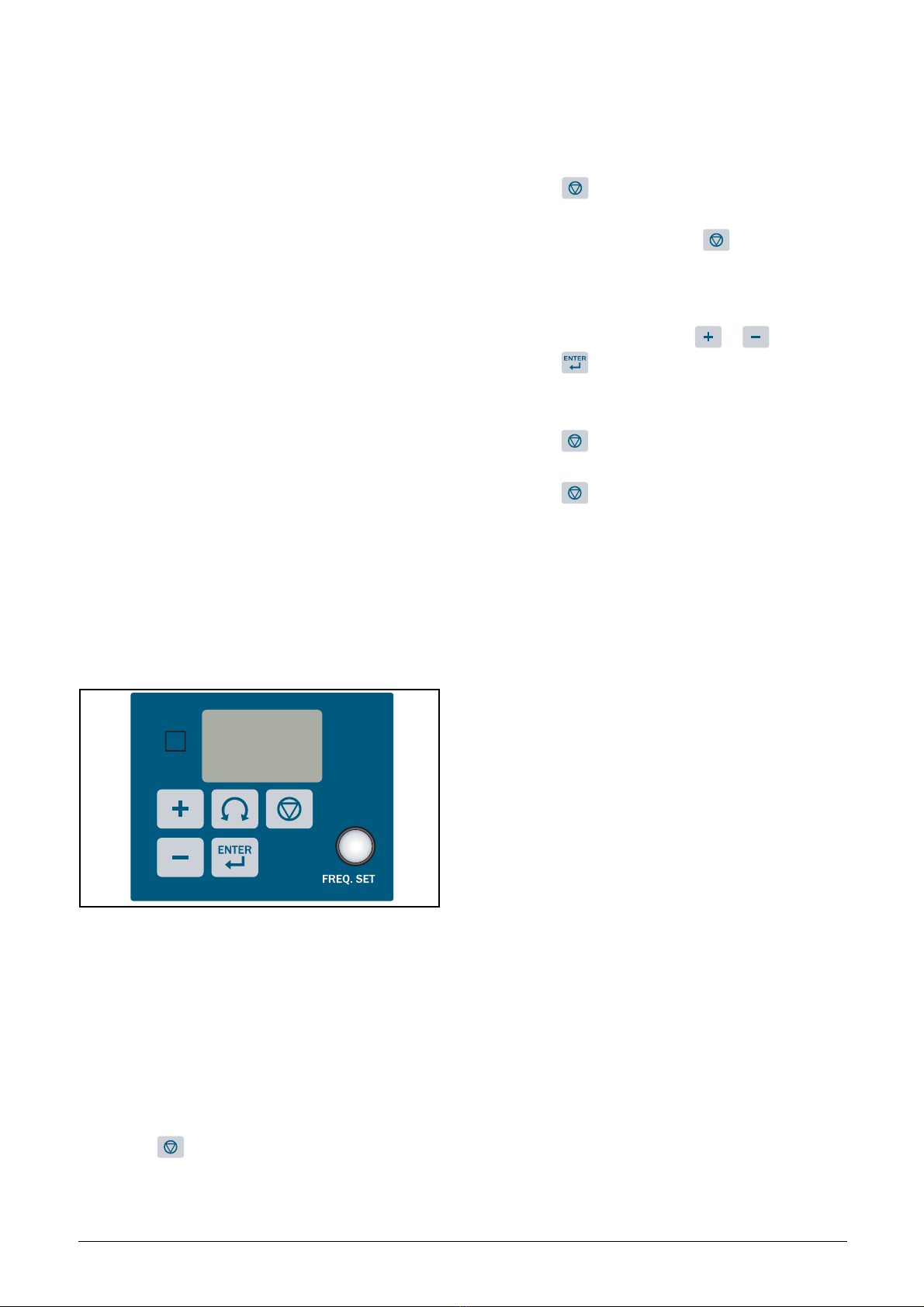
Apply AC power to the drive and observe operator. Three 7-
segment display should show power voltage for 3 to 5 sec-
onds and observe how it runs, factory sets 5.00. (Frequency
Command of 7-segment display should be flashed all the
time.)
Step3 Check motor rotation under no-
load conditions
• Press the key. The 7-segment display will indicate
the output frequency 00.0 to 05.0 Hz.
• Check the operation direction of the motor.
• If the direction of the motor is incorrect:
• Press the key, turn off the AC power supply. Once
Power indicator LED is off, change over theT1 and T2.
• Apply power again and press the key and check the
motor operation direction.
Step4 Check full speed at 50Hz/60Hz
• Change the frequency with the or and please
press the key to confirm the setting.
• Set frequency to 50Hz/60Hz according to the above reg-
ulations.
• Press the key, inspect the motor operation as motor
accelerates to full load.
• Press the key, inspect the motor operation as motor
deceleration.
Step5 Other settings
As for other function, please refer to VSA user manual.
Set acceleration time, page 37
Set deceleration time, page 37
Set upper frequency limit, page 38
Set lower frequency limit, page 38
Set motor rated current, page 32
Set control mode (Vector, V/F), page 30
Step6 vector Mode Settings
When the VSD is set to run in Vector Mode (211=000), the
motor parameters needs to be set. The required in formation
should be readily available on the nameplate of the motor.
(Motor kW=0.75 x HP)
The parameters to set for vector operation:
Motor Rated Current (Amps) [223], see page 32
Motor Rated Voltage (Volts) [221], see page 32
Motor Rated Frequency (Hz) [224], see page 32
Motor Rated Power (KW) [222], see page 32
Motor Rated Speed (RPM) [225], see page 32
Additional Vector Mode Settings to adjust for optimum
operations are:
Torque boost gain [351], see page 39
Slip compensation gain [354], see page 41
Low Frequency Voltage Compensation [352], see page 39.

Emotron AB 01-3993-01r1

Emotron AB 01-3993-01r1
Preface
Preface
To extend the performance of the product and ensure per-
sonnel safety, read this manual thoroughly before using the
variable speed drive (VSD). Should there be any problem in
using the product that can not be solved with the informa-
tion provided in the manual, contact your nearest Emotron
distributor or sales representative who will be willing to help
you.
Precautions
The VSD is an electrical product. For your safety, there are
symbols such as “Danger”, “Caution” in this manual as a
reminder to pay attention to safety instructions on carrying,
installing, operating, and checking the VSD. Be sure to fol-
low the instructions for maximum safety.
Product Inspection
The variable speed drives have all passed the function test
before delivery. Please check the following when you receive
and unpack the VSD:
• The model and capacity of the VSD is the same as those
specified on your order.
• Is there any damage caused by transportation, do not
apply the power.
Contact Emotron’s sales representatives if any of the
above problems have occurred.
Earthing
The variable speed drive must always be earthed via the
mains safety earth connection, indicated by “PE”.
Earth leakage current
This VSD has an earth leakage current which does exceeding
3.5 mA a.c. or 10 mA d.c. Therefore the minimum size of
the protective earth conductor must comply with the local
safety regulations for high leakage current equipment.
Residual current device (RCD)
compatibility
This product cause a d.c. current in the protective conduc-
tor. Where a residual current device (RCD) is used for pro-
tection in case of direct or indirect contact, only a Type B
RCD is allowed on the supply side of this product. Use
RCD of 300 mA minimum.
WARNING: Indicates a potential hazard could
cause death or serious personal injury if
misused.
CAUTION: Indicates that the VSD or the
mechanical system might be damaged if
misused.
WARNING: Do not touch any circuit boards or
components if the charging indicator is still
lit after the power off is turned off.
Do not wire when the VSD is electrified. Do not check
parts and signals on circuit boards during the VSD
operation.
Do not disassemble the VSD or modify internal wires,
circuits and parts.
Earth the ground terminal of the VSD properly. As per
200 V class, earth to 100 Ohm and 400 V class, earth to
10 Ohm or below.
CAUTION: Do not perform a voltage test on
parts inside the VSD. High voltage will easily
destroy these semiconductor parts.
Do not connect the VSD’s T1 (U), T2 (V) and T3 (W)
terminals to an AC power supply.
CMOS ICs on the VSD’s main board are susceptible to
static electricity. Do not touch the main circuit board
!
!

Emotron AB 01-3993-01r1

Emotron AB 01-3993-01r1 1
Contents
Safety Precautions ......................................... 3
1. Model description........................................... 5
2. Mounting and installation of the VSA drive.. 7
2.1 Environment .............................................................. 7
2.2 Mounting and installation......................................... 9
2.3 Wiring Rules............................................................. 10
2.3.1 Notice for wiring ...................................................... 10
2.3.2 Options and wiring specifications ......................... 11
2.3.3 Precautions for peripheral applications ................ 12
2.4 VSD Specification.................................................... 14
2.4.1 Basic specification .................................................. 14
2.4.2 General Specifications............................................ 15
2.5 VSA Wiring diagram................................................. 17
2.6 Description of VSD Terminal .................................. 18
2.7 Dimension................................................................ 19
2.8 Installation and design consideration ................... 21
3. Programming instructions and menu list .. 23
3.1 Keypad description ................................................ 23
3.1.1 Keypad display ....................................................... 23
3.1.2 Operating Instructions for the keypad ................... 23
3.2 The display............................................................... 24
3.3 Menu function list .................................................. 24
3.4 Menu function description ..................................... 30
4. Troubleshooting and maintenance ............ 55
4.1 Trouble indication and corrective action ............... 55
4.1.1 Fault/ Error display and Diagnostics ..................... 55
4.1.2 Set up configuration, interface errors.................... 56
4.1.3 Keypad operation error description ....................... 57
4.1.4 Load monitor error description .............................. 57
4.2 General functional troubleshooting ....................... 58
4.2.1 Troubleshooting flowcharts VSA series ................. 59
4.3 Routine and periodic checks.................................. 65
5. Peripherals................................................... 67
5.1 Input side AC reactor .............................................. 67
5.2 Option card .............................................................. 67
5.2.1 RS-485 option card (Model: JNSIF-485)................ 67
5.2.2 RS-232 option card (model: JNSIF-232)................ 67
5.2.3 Program copy option card (Copy Unit) (JNSIF-MP) 68
5.2.4 Remote keypad (Remote keypad) (Model: JNSDOP-
LED-2M) ................................................................... 68
5.2.5 Input/Output expansion card (model: JNSIF-IO) ... 69
6. Appendix VSA parameter list...................... 71

2Emotron AB 01-3993-01r1

Emotron AB 01-3993-01r1 3
Safety Precautions
Operation Precautions
Before Power Up
Before operation
Leakage current
During operation
The line voltage applied must comply with
the VSD’s specified input voltage. (See the
nameplate)
WARNING: Make sure the main circuit
connections are correct. L1, L2 and L3 are
power-input terminals and must not be
mistaken for T1, T2 and T3. If they are, the
VSD might get damaged.
The VSD will still stay live immediately after
power loss. When the power is re-stored, the
VSD operation is controlled by [252].
The VSD operation is controlled by [213] and
[335] and the status of (FWD/REV RUN switch) when
power is re-stored. [33A] /[226]) Power loss ride
through/Auto reset after fault).
1. When [213]=000, the VSD will not auto restart when
power is re-stored.
2. When [213]=001 and operation switches (FWD/REV
RUN) is OFF, the VSD will not auto restart when power is
re-stored.
3. When [213]=001and operation switch ON and
[335]=000, the VSD will auto restart when power is re-
stored. Please turn OFF the run (start) switch to avoid
damage to machine and injury to personnel before the
power is re-stored.
When [335]=000 (direct start on power up), please refer
to the description and warning for [335] to verify the
safety of operator and machine.
!
!
CAUTION: Make sure the model and VSD
capacity match the setting in menu [921].
WARNING: Warning! EV series built in Filter
type leakage current can exceed the IEC
standard limit of 3.5mA. Please ground the
VSD as shown in figures 3.5 and 3.6.
Operation with ungrounded supplies:
Filtered VSDs CANNOT be used on ungrounded supplies.
Unfiltered VSDs can be used on ungrounded supplies. If
any output phase is shorted to ground, the VSD may trip
with OC.(over current trip)
Operation with Residual Current Device (RCD):
A filtered VSD with the trip limit of the RCD is 300 mA
The neutral of the supply is grounded, as is the VSD.
Only one VSD is supplied from each RCD.
WARNING: Do not connect or disconnect the
motor while VSD is operating the motor. The
VSD and the disconnect device can sustain
damage from high levels of switch-off current
transients.
WARNING: To avoid electric shock, do not
take the front cover off while power is on.
The motor will restart automatically after stop when
auto-restart function is enabled. In this case, care must
be taken while working around the drive and associated
equipment.
NOTE: The operation of the stop switch is different than
that of the emergency stop switch. The stop switch has
to be activated to be effective. The operation of the Stop
command is different than that of the Emergency Stop
command. The Stop command has to be switched ON
(activated) to be effective, and be switched OFF (de-
activated) when controlling the motor speed. The
Emergency Stop command has to be switched OFF (de-
activated) to become effective and needs to be ON
(activated) to make normal operation possible.
!

4Emotron AB 01-3993-01r1
Useable environment
CAUTION: Do not touch heat-generating
components such as heat sinks and brake
resistors.
The VSD can drive the motor from low speed to high
speed. Verify the permitted speed ranges of the motor
and the associated machinery.
Note the settings related to the braking unit.
Do not check signals on circuit PCB while the VSD is
running.
CAUTION: Allow a minimum of 5 minutes
power down before attempting to
disassemble or check the components within
the drive.
CAUTION: When the VSD top dust cover has
been removed the drive can be installed in a
non-condensing environment with
temperature ranging between –10°C to
+50°C and relative humidity of 95% or less, but the
environment should be free from water and metal dust.
!
!
!

Emotron AB 01-3993-01r1 Model description 5
1. Model description
Model: VSA23-04
I/P: AC 1 PH
200-240V 50/60Hz
O/P: AC3PH 0~264V
1.6kVA 4.2 A
EMOTRON AB
VSD model
Input voltage
Output specifications
VSA 04 23
Series
Input voltage Rated output current
23: 230V 01/03/04/07/10 A
48: 460V 002/004/005 A

6Modeldescription Emotron AB 01-3993-01r1

Emotron AB 01-3993-01r1 Mounting and installation of the VSA drive 7
2. Mounting and installation of the VSA drive
2.1 Environment
The environment will directly affect the proper operation
and the life of the VSD, so install the VSD in an environ-
ment that complies with the following conditions:
Fig. 1 Panel and enclosure arrangement for drives
Place the front side of the VSD outward and the top upward
to improve heat dissipation.
Fig. 2 Mounting and clearance requirements
• All VSA drives in IP-20 Enclosures can be DIN-RAIL
mounted as shown below.
Ambient temperature: 14 to 122°F (-10 to 50°C)
Avoid exposure to rain or moisture. Avoid direct sunlight.
Avoid smoke and salinity. Avoid corrosive liquid and gas.
Avoid dust, lint fibres, and metal filings. Keep away from radio active and flammable materials.
Avoid electromagnetic interference (soldering machines, power machine).
Avoid vibration (stamping, punchpress). Add a vibration-proof pad if the situation can not be avoided.
If several VSDs are placed in the same control panel, provide heat remoual means to maintain the temperature below 50°C.
See figure 3-1 for proper drive arrangement.
(Correct) (Incorrect) (Correct) (Incorrect)
VSA VSA
VSA
VSA
Enclosure
Enclosure
Panel
12 cm
12 cm
5 cm
5 cm 5 cm
(A) Front view (B) Side view

8 Mounting and installation of the VSA drive Emotron AB 01-3993-01r1
Fig. 3 DIN-rail mounting of the VSA drive
• All VSA drives in IP-20 enclosures can be mounted side-
by-side as shown below. (ambient temperature below
122°F) (50°C).
Fig. 4 Side-by-side Mounting of the VSA Drive
1
2
1
2
3
A. DIN-rail installation B. DIN-rail removal

Emotron AB 01-3993-01r1 Mounting and installation of the VSA drive 9
2.2 Mounting and installation
Do not use the VSD in an environment with the following
conditions:
Salt
Direct sunlight Corrosive gas and liquid Oil mist
Oil
Salt Exposed to wind,
rain and water
Iron filings, dust
Strong vibration Extremely low Excessively high
temperatures
Inflammable materials
Radioactive materials
Electromagnetic waves and
(Near an electric welding machine)
ultra high frequency waves
temperatures

10 Mounting and installation of the VSA drive Emotron AB 01-3993-01r1
2.3 Wiring Rules
2.3.1 Notice for wiring
Tightening torque:
Connect cables with a screwdriver or other suitable tools per
the tightening torques listed below.
B. Power wires:
Power wires connect to terminals L1, L2, L3, T1, T2, T3, P
and N. Select power wire in accordance with the following
criteria:
1. Use wires with copper core only. Insulating materials
with diameters should be based on working conditions
at 221°F (105°C).
2. The minimum nominal voltage of 240 VAC type con-
nectors is 300 V, and 480 VAC type connector is 600 V.
C. Control wire:
Control wire is connected to the TM2 control terminal.
Select wire in accordance with the following criteria:
1. Use copper core only. The insulating materials with
diameters should be based on working conditions at
221°F (105°C).
2. To avoid noise interference, do not route the control wir-
ing in the same conduit with power wires and motor
wiring.
D. Nominal electrical specifications of the
terminal block:
The following are nominal values of TM1:
E. Fuse types
Drive input fuses are provided to disconnect the drive from
power in the event that a component fails in the drive’s
power circuitry. The drive’s electronic protection circuitry is
designed to clear drive output short circuits and ground
faults without blowing the drive input fuses. Below table
shows the EV input fuse ratings.
To protect the VSD most effectively, use fuses with current-
limit function.
RK5, CC/T type fuse for VSA
220V class(1ƒÓ)
440V class(3ƒÓ)
*Fuse ratings are based upon 300 V fuses for 120 V VSDs,
and 300 V fuses for 230 V VSDs, and 500 V for 460 V
VSDs
Securing torque
Type Power
source
Tightening torque for TM1 ter-
minal
VSA23-01/
03/04 200-240V 0.74/0.1
(LBS-FT / KG-M)
8.66/10
(LBS-IN/KG-
CM)
VSA23-07/10 200-240V
1.286/0.18
(LBS-FT/KG-M)
15.97/18
(LBS-IN/KG-
CM)
VSA48-002/
004/005 380-480V
Type Power source Volts Amps
VSA23-01/03/
04 200-240V 600 15
VSA23-07/10 200-240V
600 40
VSA48-002/
004/005 380-480V
NOTE: Nominal values of input and output signals (TM2)
– follow the specifications of class 2 wiring.
VSA
model HP kW kVA
100%
CONT
Output
AMPS
(A)
Max.
RK5
FUSE
Rating
(A)
Max.CC
or T
FUSE
Rating
(A)
VSA23-01 0.25 0.2 0.53 1.7 8 15
VSA23-03 0.5 0.4 0.88 3.1 10 20
VSA23-04 1 0.75 1.6 4.2 15 30
VSA23-07 2 1.5 2.9 7.5 20 40
VSA23-10 3 2.2 4.0 10.5 25 50
VSA model HP kW kVA
100%
CONT
Output
AMPS
(A)
Max.RK5
FUSE
Rating
(A)
Max.CC
or T
FUSE
Rating
(A)
VSA48-002 1 0.75 1.7 2.3 6 10
VSA48-004 2 1.5 2.9 3.8 10 15
VSA48-005 3 2.2 4.0 5.2 10 20

Emotron AB 01-3993-01r1 Mounting and installation of the VSA drive 11
2.3.2 Options and wiring
specifications
MCCB/ MC/ Fuse
• Warranty and replacement service does not apply to
damage caused by the following conditions.
1. MCCB or fuse is not installed, improperly installed, or
improperly sized, and has resulted in VSD damage.
2. MC or capacitor or surge absorber is installed between
the VSD and the motor.
Use a single fuse for 1 L/N model. For 3 models, each L1/
L2/L3 phase must be fused.
• Please utilize three phase squirrel cage induction motor
with appropriate capacity for VSD.
• If the VSD is used to drive more than one motor, the
total capacity must be smaller than the capacity of the
AC drive. Additional thermal overload relays must
installed in front of each motor.
• Do not install phase advancing capacitors, LC, or RC
components between VSD and motor.
VSA model VSA23 VSA48
-01/-03 -04 -07 -10 002/004/005
Fuse 10 A
300 VAC
20 A
300 VAC
30 A
300 VAC 15A/600 VAC
Main circuit terminal Wire dimension
(14AWG) 2.0mm2
Terminal screw
M4
Wire dimension
(12 AWG) 3.5 mm2
Terminal screw
M4
Wire dimension (14 AWG) 2.0
mm2
Terminal screw
M4
Signal terminal (TM2)
1 to 12 Wire dimension (#18 AWG) 0.75 mm2Terminal screw M3
L1 L2 L3 PE
PET3T2T1

12 Mounting and installation of the VSA drive Emotron AB 01-3993-01r1
2.3.3 Precautions for peripheral applications
Fig. 5 Typical installation schematic
Power
Moulded-case
Circuit breaker
Magnetic
contactor
AC reactor
for power
improvement
Variable
Motor
speed drive
Power supply:
• Make sure the correct voltage is applied to avoid damaging the
VSD.
• A moulded-case circuit breaker or fused disconnect must be
installed between the AC source and the VSD.
Moulded-case circuit breaker:
• Use a moulded-case circuit breaker that conforms to the rated volt-
age and current of the VSD to control the power and protect the
VSD.
• Do not use the circuit breaker as the run/stop switch for the VSD.
Fuse:
• A suitable fuse should be installed with VSD rated voltage and cur-
rent when a MCCB is not being used.
Earth Leakage circuit breaker:
• Install a leakage breaker to prevent problems caused by current
leakage and to protect personnel. Select current range up to
200mA, and action time up to 0.1 second to prevent high frequency
failure.
Magnetic contactor:
• Normal operations do not need a magnetic contactor. When per-
forming functions such as external control and auto restart after
power failure, or when using a brake controller, install a magnetic
contactor.
• Do not use the magnetic contactor as the run/stop switch for the
VSD.
AC Line Reactor for power quality:
• When VSDs are supplied with a high capacity (above 600KVA)
power source, a AC reactor can be connected to improve the PF.
Input noise filter:
• A filter must be installed when there are inductive loads affecting
the VSD.
VSD:
• Output terminals T1, T2, and T3 are connected to the motor’s U, V,
and W terminals. If the motor is reversed while the VSD is set to run
forward, just swap any two of T1, T2, and T3.
• To avoid damaging the VSD, do not connect the output terminals T1,
T2, and T3 to AC input power.
• Connect the ground terminal properly. (230 V series: Rg <100; 460
V series: Rg <10.): <10Ω.
VSC23/48

Emotron AB 01-3993-01r1 Mounting and installation of the VSA drive 13
Make external connections as shown in figure 3-10. Check
after wiring to make sure all connections are correct. (Do
not use the control circuit buzzer to check connections)
(A) Main circuit must be separated from other high voltage
or high current power line to avoid noise interference. Refer
to following figures:
• A noise filter in the output of the main circuit can sup-
press conductive noise. To prevent radiative noise, the
wires should be put in a ferromagnetic metal pipe and
separated from all other signal lines by at least 1ft.
Fig. 6 Installation examples with adjacent signal conductors
• The power supply and output PE terminals must be
both connected to ground to increase noise immunity of
the built-in Filter.
Fig. 7 Grounding filtered units
(A)The control circuit wiring and main circuit wire/ other
high voltage/current power wiring should be separated to
avoid noise interruption.
• In order to prevent noise interference which could cause
VSD faults, the control circuit signal should be shielded
and twisted. Please refer to fig. 8. The wiring distance
should be less than 150ft (50m).
Fig. 8 Processing the ends of twisted pair cables
(B) Connect ground terminals as follows: (200 V class
ground <100; 400 V class ground <10.)
• Ground wiring AWG is sized per the electrical equip-
ment specifications and should be made as short as possi-
ble.
• Do not share the ground of the VSD with other high
current loads (welding machine, high power motor).
Connect the terminal to its own ground.
• Do not make a loop when several VSDs share a common
ground point.
(a) Good (b) Good (c) Bad
Fig. 9 Grounding examples: multiple drives
(C) To ensure maximum safety, use correct wire size for the
main power circuit and control circuit.
(See table in section 2.3.2, page 11)
(D) Verify that all wiring is correct, wires are intact, and ter-
minal screws are secured.
N
o
i
se
Filter
Noise
Filter
~M
Power supply
MCCB Metal box
Noise
filter Noise
filter
VSC23/48
Metal pipe
Signal wire
above
Controller
M
L1 L3 PE
T1 T2 T3 PE
Ground
Protective jacket
Shielded wire
Do not connect this end
Wrapped with insulation
To ground terminal
(refer to instructions
of filter wiring)

14 Mounting and installation of the VSA drive Emotron AB 01-3993-01r1
• When the connection between the VSD and the motor
is too long, consider the voltage drop of the circuit.
Phase-to-phase voltage drop (V) = 3×resistance of wire (/
km)×length of line (m)×current×10-3. And the carrier
frequency must be adjusted based on the length of the
line.
2.4 VSD Specification
2.4.1 Basic specification
* Based on a 4-Pole Motor
The length of the line between the VSD and
the motor Below 25 m Below 50 m Below 100 m Over 100 m
Carrier Frequency Below 16 kHz Below 12 kHz Below 8 kHz Below 5 kHz
Settings in menu [226] 16 12 8 5
Model
230 V model
Single phase VSA
23-01 23-03 23-04 23-07 23-10
Max.Applicable Motor output.HP*1 (kW) 0.25
(0.2)
0.5
(0.4)
1
(0.75)
2
(1.5)
3
(2.2)
Rated output current (A) 1.7 3.1 4.2 7.5 10.5
Rated capacity (kVA) 0.53 0.88 1.60 2.90 4.00
Input voltage range (V) 1PH, 200 to 240V+10%,-15%(50/60Hz)
Output voltage range (V) 3PH 0 to 240V
Input current (A) 4.3 5.4 10.4 15.5 21
VSD with filter weight kb (kg) 1.57 (0.71) 1.71 (0.73) 1.71 (0.73) 2.76 (1.25) 2.87 (1.3)
Maximum momentary power loss time (S) 1.0 1.0 1.0 2.0 2.0
Enclosure IP20
Model
460 V model
VSA48-(F)
002 004 005
Max.applicable Motor Output HP*1 (kW) 1.0 (0.75) 2.0 (1.50) 3.0 (2.2)
Rated output current (A) 2.3 3.8 5.2
Rated capacity (kVA) 1.7 2.9 4.0
Input voltage range (V) 3PH 380 to 480V+10%,-15% (50/60Hz)
Output voltage range (V) 3PH 0 to 480V
Input current (A) 34.86.6
VSD with filter Weight Lb. (kg) 3.70 (1.37) 3.75 (1.4) 3.82 (1.45)
Maximum momentary power loss time (S) 1.0 2.0 2.0
Enclosure IP20

Emotron AB 01-3993-01r1 Mounting and installation of the VSA drive 15
2.4.2 General Specifications
Frequency control
Range 0 to 200 Hz
Initial Drive 100%/3 Hz (Vector mode)
Speed Control Range (Vector mode) 20:1
Speed Control
Precision ±0.5% (Vector mode)
Setting resolution¡ see note 1 Digital: 0.1 Hz (0 to 99.9 Hz)/1 Hz (100 to 200 Hz); analogue: 0.06 Hz/ 60 Hz
Keypad setting Set directly with keys or the VR on the keypad
Display 7 segment*3 Displays; frequency/DC Voltage/Output Voltage / Current/ VSD parame-
ters/fault log/program version/PID feedback control potentiometer.
External signal setting •External
•Performs up/down controls with multi-functional contacts on the terminal base
Frequency limit function Upper/lower frequency limits, and two skip frequencies.
Carrier frequency 4 to 16 kHz (default 10 kHz, above 10 kHz with De-rating)
V/F pattern 6 fixed patterns 50 Hz/60 Hz, 1 programmable
Acc/Dec. control Two-stage acc/dec time (0.1 to 999 s)
Multi-functional analogue
output 6 functions (refer to [531] description)
Multi-functional input 19 functions (refer to [521] to [524] description)
Multi-functional output 16 functions (refer to [551] description)
DI (digital input) NPN/PNP alternative: 4 points standard, 2 points optional (S1 to S4 standard, S5 to S6
optional)
General control
DO (digital output) Relay output *Form A contact ---- set to multi-function output. External multi-function out-
put *option 1 point (open collector transistor 24 V, 600 mA)
AI (analogue input) Set speed command and PID feedback signal (speed, PID 4–20 mA /0–10 V) or MFIT S7
Other functions Instantaneous power loss on restart, Speed search, fault restart, DC injection braking,
Communication control •RS485 Option card: Modbus RTU/ASCII mode, 4800 to 38400 bps, max. 254 stations
Operation temperature 14 to 122°F (-10 to 50°C) IP20, 14 to 104°F (-10 to 40°C) IP65
Storage temperature -4 to 140°F (-20 to 60°C)
Humidity 0 – 95% RH (non condensing)
Vibration immunity 1G (9.8 m/s2)
EMI/EMS Compatibility Built-in filter in accordance with EN61800-3 first environment
LVD Accordance with EN50178
Enclosure IP20
Safety Class UL508C
Table of contents
Other Emotron Inverter manuals
Popular Inverter manuals by other brands

Solutronic
Solutronic SOLPLUS 100 Short installation manual

Generac Power Systems
Generac Power Systems 004709-0 owner's manual

GE
GE 040316-0 Illustrated parts list

Dometic
Dometic MSI912 Installation and operating manual

Growatt
Growatt SPF 2000TL user manual

RoseWater Energy
RoseWater Energy Hub SB20 installation manual

Mitsubishi Electric
Mitsubishi Electric FR-A7NP instruction manual

Peak
Peak NG3000 user manual

Generac Power Systems
Generac Power Systems Liquid Cooled Gas Engine Generator Sets None Specification sheet

Elby Designs
Elby Designs EURO SERGE ES Series manual

Selectronic
Selectronic SP PRO 2i Series Installation notes

Hobart
Hobart JET-EX 4 Operation and maintenance manual