3
- Please set the generator on a at hard horizontal surface. To reduce vibration
during operation and to avoid damage to the surface, where the generator is
installed, it is equipped with dampers.
- Please don’t use the generator near ammable gases, liquids or dust. When
using the generator exhaust system gets very hot. This may cause re or
explosion of these materials.
- Be sure to follow cleanliness and good lighting in the work area. Clutter and
poor lighting may cause an injury.
- Do not let the presence of unauthorized persons, children or animals when
working with generator. If necessary, make sure to fencing the working area.
- Please use safety shoes and protective gloves when working with generator.
2.2. ELECTRICAL SAFETY
- The generator produces electricity that may lead to an electric shock while
neglecting compliance regulations.
- In the high humidity level conditions generator exploit is prohibited. Keep the
generator in a dry place only.
- Avoid direct contact with grounded surfaces (pipes, radiators, etc.).
- Do not allow moisture in the generator. The water inside the device increases
the risk of an electric shock.
- Be careful when working with power cables. Immediately replace it in case of
damage, as damaged wire increases the risk of electric shock.
- All connecting the generator to the network must be made by certied
electrician in accordance with all electrical rules and regulations.
- Connect the generator to the protective ground before operation.
- Do not connect or disconnect a generator to electricity consumers, which are
placed in water on a wet or damp soil.
- Do not touch parts of the generator under voltage.
- Connect the generator to those customers only which meet the electrical
characteristics and the rated power of the generator.
- Store all electrical equipment dry and clean. Wires with damaged or spoiled
insulation should be replaced. You should also replace worn, damaged or rusty
contacts.
2.3. PERSONAL SAFETY
- Be careful. Do not operate the generator, if you are tired, under the inuence of
drugs or alcohol. Inattention may cause a serious injury.
- Do not wear loose clothing or jewelry when working. Long hair, jewelry or loose
clothing may get into the moving parts of the generator and cause an injury.
- Avoid inadvertent start. Make sure to set the switch to O when you turn o
the generator.
- Make sure no outsider objects are on the generator when it is turned on. Do not
overload the generator, use it only for the purpose. Proper use of the generator
will do the job for which it is designed better and safer.
- Using device for other purposes deprives the right for free warranty. It is not allowed
to sit or stand on the generator.
- Always keep a stable position and balance when starting the generator.
- Use safety equipment. Always wear goggles, a mask, non-slip sole shoes,
protective helmet, headphones.
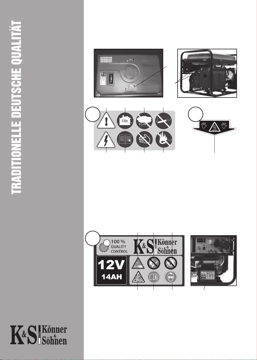
The device generates electricity. Follow safety precautions to avoid
electric shock.
! !
ATTENTION - DANGER!