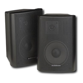
EMP Tek CS100 User manual

CS100 / CS100C
I n s t a l l a t i o n & O p e r a t i o n M a n u a l
COMPACT SPEAKERS
382 Marshall Way, Layton, Utah • USA • 84041
Toll Free: (800) 543-2205 • Fax: (801) 543-3300
www.destinationaudio.com
It is Destination Audio policy to continuously incorporate improvements into our products; all specications
are subject to change without notice. Copyright © 2007 Destination Audio. All Rights Reserved.

1
Introduction
Compact Theater Speakers
Congratulations on your purchase of Destination Audio compact theater speak-
ers! Your speakers are the result of many years of research and development
dedicated to producing powerful, high-quality home audio systems. Sophisticated
computer modeling and measurement techniques are used extensively in the
Destination Audio speaker design process.
This manual contains setup recommendations and specications for the CS100 &
CS100C compact theater speakers. It is highly recommended you thoroughly read
through the material contained in this manual before connecting your speakers.
This will ensure you have an understanding of how to properly setup, operate and
maintain your speakers for optimum performance and maximum enjoyment.
CS100C Center Channel Speaker
CS100 Surround Speaker
Break In Period
Allow 18-24 hours of listening time for your speakers to adequately break-in.
During this period, the driver suspensions will loosen, the result will be an
increase in bass, improved denition, and increased clarity and detail.
Care and Cleaning
To maintain the speaker’s high quality appearance, it is recommended you regularly
use a dry or slightly-damp soft cloth to keep the exterior of your speakers free from
dust, lint or dirt. To clean dust from the grille, use a vacuum with a brush attachment
and gently brush the surface of the grille.

2
Features
Proprietary Aluminized Fiberglass Matrix cone woofers are the heart of the
Destination Audio CS100 & CS100C speakers. This special material is stiff,
lightweight, and has self-damping properties which helps provide a virtually
uncolored audio reproduction. These woofers have a powerful magnet that gives
them high excursion capabilities; this helps the CS100 & CS100C provide an
extended dynamics and frequency response not typically found in speakers of
their size. To avoid any interference with tube-type televisions and monitors, the
CS100C is video shielded using additional opposing magnets and steel cups to
cancel any stray magnetic elds.
High frequencies are handled by a high-quality nano-silk tweeter. This tweeter
uses liquid cooling to allow for greater power handling. This allows the tweeter to
last longer and provide accurate reproduction at the higher power output levels
today’s amplier systems are capable of. The CS100C's tweeter’s magnet is
also shielded to prevent any stray magnetic elds from negatively affecting the
speaker’s environment.
Steep crossover network slopes are used to integrate the CS100 & CS100C’s
woofers and tweeters. The use of steep crossover slopes allows higher than
average power handling, minimizes the audio interaction between the drivers,
and maximizes the speaker’s overall clarity by allowing each driver to specialize
in its own respective frequency band. One component featured within the CS100
& CS100C’s crossover networks is a polyswitch. A polyswitch, or current-limiting
device, is used to prevent damage to the tweeter if the speaker is over-driven or
fed a distorted audio signal. This device operates 900% faster than a fuse and
self-resets when the volume level or amount of distortion is reduced.
The CS100 & CS100C enclosures have a narrow prole to minimize the impact
the cabinet has on the audio signal. The speakers virtually disappear, leaving
only a wide, deep sound stage with pinpoint imaging typical of much higher
priced speakers. A special damping material is also used inside the cabinet
to dampen the internal standing waves which helps these speakers provide a
true-to-life experience.

3
To obtain the best possible sound quality from your CS100 & CS100C speakers,
it is important to place the speakers where they will sound best in your listening
room. Your room will inuence the balance, imaging and overall sonic quality of
the system, so you may want to experiment with speaker placement to determine
which location offers the best overall sound for each speaker. As a general guide,
use the room layout diagram and the following descriptions when setting up a
home theater system. Some speakers shown in the diagram may not always
be applicable to your individual system.
Front Main Left and Right Speakers
As a suggested starting point for the front left and right main speakers, try to
place your speakers about 15 inches away from the wall and 7 feet apart from
each other. The distance from the listening position to each speaker should be
System Setup
Attaching Mounting Bracket
A mounting bracket and the necessary hardware are included with the CS100 to
allow them to be mounted to a wall or speaker stand. Choose a suitable location
for the speakers, and use four screws to mount each bracket to the surface
of the chosen area. If mounting on drywall, use the four drywall wall anchors
(included) to increase the sturdiness of the mount. First, use a pencil to mark
the location of each of the four holes, and then use a Phillips head screwdriver
to screw the drywall anchors into the drywall. Then place the bracket against
the wall and use four screws (placing one in each drywall anchor) to fasten the
bracket to the wall. Place the speaker against the bracket, lining-up the speaker’s
threaded insert against the hole in the bracket, and use the Attachment Knob
to fasten the speaker to the bracket. Pay close attention to face the speaker in
the desired direction before tightening the Attachment Knob.

4
close to the distance that separates the two main speakers (i.e.: a triangle).
The Destination Audio CS100 & CS100C compact theater speakers can also
be hung on a wall or placed in bookshelves to better match your décor. If this is
how your system will be arranged, keep in mind the spacing comments above
for best performance. Also, slightly angling the speakers inward towards the
listening position may give a more spacious and realistic sound stage.
Center Channel Speaker
For optimal performance in surround sound applications, the center channel
speaker (typically the CS100C) should be placed in the middle between the
front left and right main speakers. Often this positioning dictates placing the
center channel speaker either directly above or below a television or monitor.
Since the CS100C compact theater speaker features video shielding, it may be
placed in close proximity to any television without cause for concern. Also, the
CS100C may be placed in either a horizontal (lying down) or vertical (standing)
position.
Surround Channel Speakers
The surround channel speakers should be placed slightly above and behind,
and/or to the sides of, the listening position. For best performance, try to keep
the listening position centered between the surround channel speakers. You
may want to experiment with angling the surround speakers either towards
or away from the listening position (depending on your décor and your room’s
furnishings) to obtain better sound quality.
Subwoofer
Placement of the subwoofer will largely determine the quality, quantity, and
extension of the bass frequencies in your listening room. Bass frequencies are
reinforced by close room boundaries. Placing the subwoofer nearer to a corner
will make the subwoofer sound louder and boost the very lowest frequencies.
Placing the subwoofer away from a corner or walls will provide the least
reinforcement, possibly making the bass sound subjectively thinner than if the
subwoofer were closer to a wall or corner. A good starting point for subwoofer
placement would be along a wall and up to 3 feet from the corner. You may want
to experiment with subwoofer placement and the subwoofer amplier controls
to achieve the proper bass balance.
System Setup (continued)

5
NOTE: There are several different surround formats available. Dolby Pro-Logic, Pro-Logic II, Dolby Digital and
DTS generally have a 5-speaker plus subwoofer setup. Dolby Digital EX and DTS ES add an additional center
rear speaker. Some newer receivers also offer the use of 7 or more effects channels. Please consult your
audio/video professional to determine which surround format and system is best for you and how many
speakers you will require.
System Setup (continued)

6
The CS100 & CS100C use spring-loaded speaker wire terminals to rmly hold
either a pin connector or bare speaker wire. To obtain a better connection, it
is important to slightly tug on the wires after they have been secured in the
terminals. This will cause the small teeth inside the connectors to 'bite' into the
wire. It is recommended that you use wire which is color-coded or marked on
one side. If the distance is less than 50 feet long from the amplier or receiver
to the speaker, use 16-gauge or larger wire; if the distance is more than 50 feet
long, use 14-gauge wire.
WARNING: Avoid routing the speaker wire near other electrical wires, and avoid
nailing or stapling the speaker wire.
1. Separate the last 4 inches of the speaker wire conductors at each end of
the wire.
2. Use a wire stripper to remove about ¼-inch of insulation from the end of
each conductor.
3. Twist the ends of each conductor to secure loose strands.
4. Connect the positive wire to the red terminal on the back of the speaker
by pressing down on the red positive (+) terminal's tab, inserting the end
of the positive conductor, and releasing the tab.
5. Repeat this procedure to connect the negative conductor to the black
negative (-) terminal.
Attaching Speaker Wires
4
3
2
1

7
Model CS100 CS100C
Frequency
Response:
100Hz – 20Hz ±3dB 100Hz – 20Hz ±3dB
Sensitivity: 85dB (2.83V@1m) 88dB (2.83V@1m)
Recommended
Power:
35-100 Watts 35-120 Watts
Woofer: 4" Aluminum Fiberglass Matrix Dual 4" Aluminum Fiberglass Matrix
Tweeter: 1" Nano-Silk 1" Nano-Silk
Impedance: 8 Ohms 6 Ohms
Crossover
Frequencies:
3000 Hz 3000 Hz
Viedo
Shielding:
No Yes
Dimensions: Width: 5"
Height: 7¾ "
Depth: 5"
Width: 14½"
Height: 5"
Depth: 6"
Grille: Black Black
Finish: Black Black
Weight: 3 lbs. 5.9 lbs.
Specications

8
Warranty
Your Destination Audio CS100 & CS100C speakers are covered by a limited
warranty against defects in materials and workmanship for a period of ve
(5) years from the original date of purchase. This warranty is provided by the
authorized Destination Audio dealer where the speaker was purchased. Warranty
repair will be performed only when your purchase receipt is presented as proof
of ownership and date of purchase. Defective parts will be repaired or replaced
without charge by your dealer’s store or the location designated by your dealer
authorized to service Destination Audio products. Charges for unauthorized
service and transportation cost are not reimbursable under this warranty. This
warranty becomes void if the product has been damaged by alteration, misuse
or neglect. Destination Audio assumes no liability for property damage or any
other incidental or consequential damage whatsoever which may result from
the failure of this product. Any and all warranties of merchantability and tness
implied by law are limited to the duration of this express warranty. Some states
do not allow limitations on how long an implied warranty lasts, so the above
limitations may not apply to you. Some states do not allow the exclusion or
limitation of incidental or consequential damages, so the above limitation or
exclusion may not apply to you.

CS100 / CS100C
I n s t a l l a t i o n & O p e r a t i o n M a n u a l
COMPACT SPEAKERS
382 Marshall Way, Layton, Utah • USA • 84041
Toll Free: (800) 543-2205 • Fax: (801) 543-3300
www.destinationaudio.com
It is Destination Audio policy to continuously incorporate improvements into our products; all specications
are subject to change without notice. Copyright © 2007 Destination Audio. All Rights Reserved.
This manual suits for next models
1
Table of contents
Other EMP Tek Speakers manuals
EMP Tek
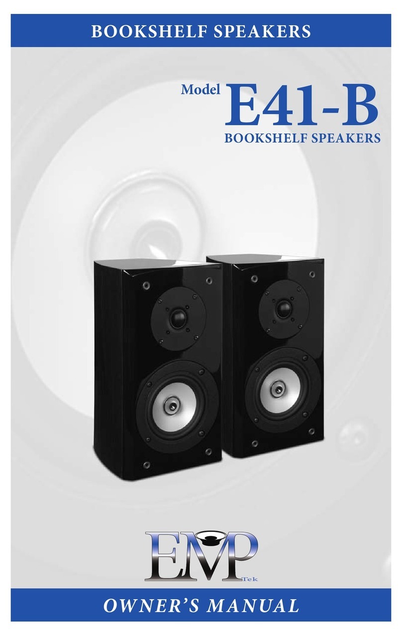
EMP Tek E41-B User manual
EMP Tek
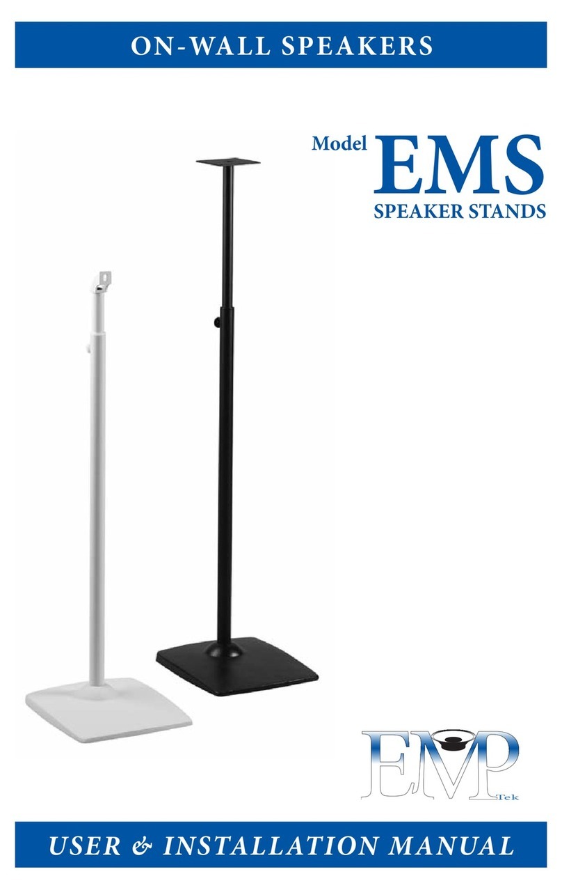
EMP Tek EMS Guide
EMP Tek
EMP Tek EF30 SERIES User manual
EMP Tek
EMP Tek E3c Guide
EMP Tek
EMP Tek ER8 User manual
EMP Tek
EMP Tek EF50 SERIES User manual
EMP Tek
EMP Tek ECA4 Guide

EMP Tek
EMP Tek 41-SE User manual
EMP Tek
EMP Tek IMPRESSION SERIES User manual
EMP Tek
EMP Tek EW25 Guide

