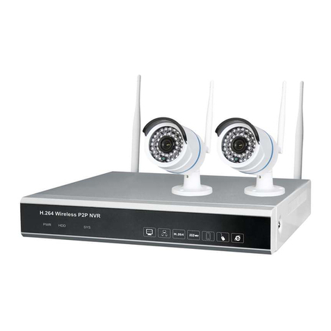
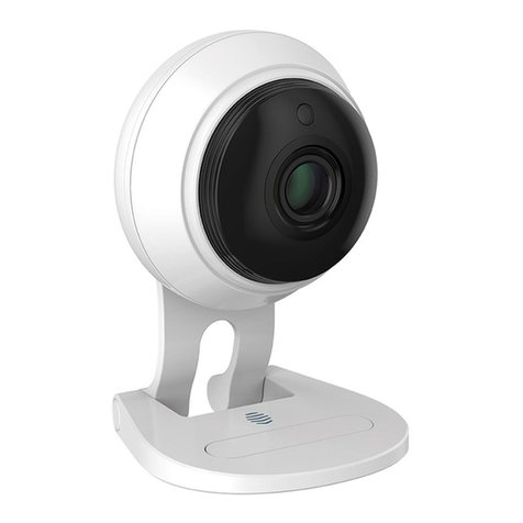
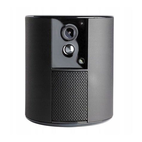
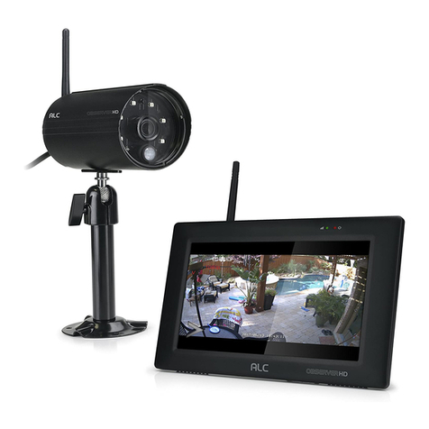
Emperor CWT-5500 User manual

CWT-5500 &MWM-1562 SERIES
TINSE053C--001

Table of Contents
1. Location of controls on Camera
2. Location of controls on Monitor
3. Connections/Setting up
4. Specfications
1
2
3~7
8~9
Camera Transmitter:
1. Transmit Frequency:
2400~2483MHz
2. Microwave Output Power:
94 dBu FCC/10mW(BZT)
3. Modulation: FM
4. Maximum Frequency Deviation:
20 MHz
5. Audio Sub, Carrier Frequency:
5.5 MHz, 5.74
6. Infrared Detection Range:
1~2 meter
7. Operation Current:
300 MA MAX.
8. Dimension:
Monitor Receiver:
1. Receiver Frequency:
2400~2483MHz
2. Receiver Sensitivity:
-80 ~ -85 dBm
3. Monitor Type: Black&White
4. Video Output: 1 Vpp 75 ohm
5. Audio Output: -8dBs 47K ohm
6. Monitor Center horizontal
Resolution: 330 lines
7. Operation Current: <1A
8. Power Supply:
Adaptor: DC 12V 1A
Battery: 10 pcs size
"C" Alkaline Battery(optional)
9. Dimension:
9
114W 55 122DH m/m 160W 160H 196D
m/m
Notice: The changes or modifications not expressly approved
by the party responsible for compliance could void the user's
authority to operate the equipment.

Location of controls on camera
2
3
4
6
8
7
9
1. Patch Antenna
2. Infra-red Lighting
3. Wide-angle Camera Lens
5. Off/On/Night Switch
4. Microphone
6. Wall Mount Lug
7. Channel Selector Switch
8. DC Input Jack
9. Audio/Video Input
1
5
Specifications
General:
1. Operation Frequency:
2400MHz - 2480MHz
3. Video: a) Input Impedance:
1 Vpp 75 ohm
b) Frequency Response:
0~5 Mhz
4. Audio: a) Input Impedance:
10K ohm
b) Interface Level:
1 Vpp
c) Frequency Response:
300 - 3400 Hz
81
2. Usable range: 30 ~ 50 Meter
5. Operation Temperature:
-10~50 C

2. 5 inches/12.5cm CRT
1. Patch Antenna
3. Power Indicator
4. Off/Audio/Video Switch)
5. Contrast Control
6. Brightness Control
7. Volume Control
8. Speaker
Location of controls on monitor
9. Channel & timer selector
10. DC Input Jack
11. Audio/Video Output
12. V-Hold Control
7
Audio Function:
Connections/setting up
When the Monitor is switched to
"Audio" position and the Camera
is at power on, there will be no
picture on the Monitor screen.
The unit is using a small amount
of power and is audio operational.
You can hear the sound signal
that captured from the monitoring
area. The Monitor
Audio/Video Link Option:
An additional security feature
of this 2.4Ghz AV Monitor is that
.
will resume Video picture when
you switch to the "Video" position.
3
The Video and Audio output
jacks are located at the back
of the Monitor. These need to
be connected to the Video
Input and Audio Input jacks
on your VCR or television
with "RCA type" cable
available at your local
electronics retailer.
you can link the Monitor to a
VCR for recording what ever
the camera sees. Also, you
can link to a conventional
television that has a "Picture-
In-Picture" feature that allow
you to take a glance to the
monitoring area all the time
while watching your favorite
TV program.
2

Connections/setting up
3
6
Connections/setting up
Installing /
Removing Batteries:
Monitor-
1. Remove the battery cover as
shown below.
2. Insert (or remove) the 10 size
"C" batteries as below.
Note: Install batteries as shown
by the battery compartment
marking only..
AC Adaptor Use:
Make sure that proper AC adaptors
have been installed correctly. Use
only the AC adaptors supplied with
the Monitor.
1. Install the plug of the AC
Adaptor to the DC jack of
the unit.
2. Plug the adaptor into a
standard wall outlet.
3. Switch on the power switch
of the unit.
4. The power indicator will be
illuminated.
Channel & Timer Setting
Sw5
Sw6
ON
ON
OFF
ON
OFF
OFF
ON
OFF
Switcher
time
3sec 5sec 7sec 10sec
1.The channel & Timer selector on the REAR cabinet used
for channel & timing setting .put the switch to on position,
than you can select single channel 1-4 or any other channel
combination.
2.Timer setting defaut as below.
CH
TIMER

Connections/setting up
To prevent speaker and Microphone
feedback noise, the Monitor should
be placed far enough away from the
Camera.
If the picture rolls up or down, the
V-Hold control located on the back
of the Monitor needs to be
adjusted.
Once you have a clear and crisp
picture displayed on the screen,
you can adjust the brightness
and contrast by using the controls
on the front of the Monitor until
you achieve the desired result.
Battery Use:
The monitor requires 10 size "C"
batteries when powered by battery.
Alkaline batteries are recommend-
ed for longer viewing time.
1. If you are using batteries in the M-
onitor and the video image starts
to shrink, it's time to change the
batteries.
2. Do not mix old and new batteries.
3. Do not mix alkaline, standard
or rechargeable batteries.
4. Remove the batteries during long
period of non-use.
4 5
The infrared lighting of the camera is
designed to allow the camera to pick
up pictures clearly during darkness or
periods of very low levels of light.
Slide switch to night position on
whenever needed. Please remember
that if you intend to use the camera
in the dark, it will only monitor objects
placed within 6ft/2m of its infrared
sensor.
Place the Camera in the most
appropriate location for monitoring
(tabletop, dresser or wall mount)
Point the camera lens toward the
area you want to pick up picture.
Make sure that both units are on the
same channel.
Check the video reception on the
Monitor screen.
Adjust the quality of the picture by
using the Contrast, Brightness and
VHold adjustment knobs on the
back and front of the Monitor.
In case of poor display quality,rotate
the antennas or reposition of both
units to obtain optimal picture
transmission.
Connections/Setting up
This manual suits for next models
1
Table of contents
