Empire Professional Audio SNT-800 User manual

A u t o - c h a n n e l - s e l e c t i ng
i n f r a r e d f u n c t i o n
P r o f e s s i o n a l w i r e l e s s
microphone with optional
m u l t i - c h a n n e l
m a n u a l
UHF
200 optional c h anne l s
Auto-channel-selecting infrared function
UHF
P r o f e s s i o n a l W i r e l e s s M i c r o p h o n e
USER GUIDE
Professional wireless microphone
Thankfulness on purchazing our products. Please
read this user guide carefully before using, just to
ensure the microphonecould be perfouned optimally
Product: Wireless Microphone
Model: SNT-800

Profile
Welcome to our company! we
professionally produce UHF with
2 0 0 - c h a n n e l f u n c t i o n w i r e l e s s
microphone. They are adopted multi-
channel synthetic technology of DPLL
(digital phase-locked loop), and
pilotone technology. Within 50-meter
frequency band, preset 200 channels,
and then utilize infrared to select
channel and the system may pair
every of them and set automatically.
In this case, any microphone in the
system wold match the channel of
the receivers in the system. Especially
suitable for the occasion with several
sets being used simultaneously.
-1-
640-689.75MHz
broadband FM
200
250KHz
±0.005%
100dB
±45KHz
60Hz-18KHz(3±dB)
> 105dB
≤0.5%
about 100m (under the situation of no interruption
-10℃- - +50℃
superheterodyhe
110MHz,10.7MHz
BNC/50Ω
12dBuV (80dB S/N)
12-32dBuV
≥75dB
+10 dBV
Technology specification
-14-
System Parameter:
work frequency:
modulation mode:
channels
channel frequency:
Frequency stability:
dynamic bound:
max excursion:
frequency response:
S/N
T.H.D
operation distarce:
working environment
temperature:
Receiving machine index:
receiving machine mode:
IF
antenna receive:
sensitivitive adjustable rang:
sensitivitire:
erratic control:
max output frequency
hand microphone has on in built helix
ant enna transm itter 1/4 w are-l e rgh
flagelliform antenna
Transmitter index:
antenna:
output frequency:
erratic control:
power supply:
battery vitality:
max frequency 30mw; min frequency 3mw
-60dB
2 1.5V alkaline batteries
about 10 hours under normal frequency
transmittion, about 15 hours under low
frequency transmittion.

-2-
do not operate our baby of the situations as above! Only professionals can
disassemble and assemble the system!
Warning: Beware of electric shock fine; machine must be kept
away humid conditions!
Contions
please do not open up the system.
technicians are always the only per son s
to s o r t out a n y techn i c a l operat i o n s .
strictly readers are told
Welcome and thank you for pu chazing our wireless microphone system!r
With years experience to producing wireless microphone system, our crews are
confident to say we are the expert of manufacturing wireless microphone system.
Ou r p ro d uct s a re s u it a b le f o r K T V roo m , ka r aok e s ta g e an d a ls o s ch o o l,
showplace, stadium, and so on. Our products are convenient to operate, and of
stably great quality. So they are widely favoured by our customers We promise
highly of first class quality, and also first class service. Our professional technician
crew is always ready to help you with any technical questions!
1. read the user guide-read carefully about safety and manipulation requests.
2. keep the manipulation introductions-please keep this manual for further need
of safety and manipulation requests.
3. beware of the warnings-please notice the warnings for the machine while operating.
4. follow the denotements-please follow the denotements while operating.
5. accessional devices-only accessional devices from original producers of the
machine are required.
6. humidity cautions-keep the machine away from humid condictions.
7. aeration-please keep the machine in well ventilated conditions at all time, there
should be at least 5cm clearance around the device.
8. heat source-please keep the devices away from heat sources, including, radiator,
heater, stove, etc.
9. power supply-please utilize the labelled voltage on the device.
10. no exposed fire should be on the device e.g. flaming candles.
11. please do not litter the batteries, dispose them into the appointed place when
they are fully used.
12. no liquid or weights should be on the device, no water dripping or splashing
onto lin to the device.
13. the device is also suitable in torvied zone, and variable zone.
Problem & solution
-13-
Situation Solution
No voice; (situation: the receiving machine
RF display can not come on)
Check the transmitter and the receiving machine, see
whether it is on the play of "ON"
Check whether the "negativre" and the "positive" pole
of the battery is confusing.
Check the connecting sol tion of the receiving machineu
and the aerial.
Make sure that there is no block betwee the aerial and
the transmitter.
No voice; (situation: RF display is nomal; AF
display is nomal)
Check whether the voice re knob of the receiving machine
is on the lowest place.
Check whether the connecting between the loudspeakers
of the receiving machine are nomal.
Check whether the power of the transmitter is open
Exchange the mike of the transmitter when it is necessary
No voice; (situation: RF display is nomal; AF
display is un-nomal)
Put through the transmitter, there is some noise
or some interruption noise in the receiving
signal
Check whether the battery is tight enough.
Eliminate the RF source of the disturbance rearby.
Check the connecting situotion, if using githar or other
mascial insturment.
If both of the transmitters are using the same frequency,
check it and close one lof them.
Maybe thesignal is too infirmness, adjust the place of the
antenna more it as near the transmitter as possible.
Replace other channel.
There is some noise, after closing the
transmitter.
Adjust the sensitivity button of the transmitter; the "SQ"
button.
Eliminate source of noise of RF.
Adjust the place of the receiving machine or the place
of the antenna over again
Can not open the transmitter Change the battery of the transmitter.
While the showplace is moving. the voice from
the transmitter may get lost sometimes.
Adjust the sensitivity button of the transmitter; the "SQ"
button.
Locate the receiving machine over again and hare the
"on-show" experiment, obserre the RF display.
If you find some voice lost, tag the point and avoid this
point when performing.

Operation method and attentions
-12-
Operation method:
1.Connect the audio system well;
2. Set the volume of the receiving machine and the loudspeaker to mix;
3.Turn on the power of the audio system from backing stage to backward stage;
4.Trun on the power of the transmitter;
5. Adjust the audio effect of the audio system: firstly, adjust the volume of the receiving
machine to the middle point, turn on the microphone, talk directly forward the
microphone, fit the volume secondly, adjust the tone, volume controller carefully
and make the voice clear, the volume suitable. Hdd the phone and hare the "on
show" proless;
6. If the wireless receiving machine system has some problems. Please reference
this funcation hare troubleshooting and solve the problem. If the problem is not in
the troubleshooting. Please onse the professional to sowe it or hegotiate with the
franchiser;
7. After using, please turn off the power of the transmitter, than turn off the power of
al l the owdio system from backing stage word backword stage.
Attentions:
1. The erect location of the antenna effect the leleption effect of the leceivting machine
directly, so take attention to the installation method. If is the most important principle
that keep the distance between the microphone and the leceiving machine shortest.
2. Avoid putting the receiving machine hear the computer or other equipment which
can produce RF signal.
3. Avod putting the receiving machine in the orlop of the DB, exclude the installation
antenna from distance.
4. This receiving machine system can fill 200 microphone at the same time, and it
could not disturb each other. If need to be adjusted different channels by professional.
5. When some wireless systems are used at the same time, pleas take attention to
the setting of "SQ" of the receiving machine. The lower the sensitive is the shorter
the capacity of disturbance cou d be! It is better that the transmit phone is short.l
It can save the electronic and decrease the jamming at the same time.
The are components in the wireless sound conducting system as below:
●One wireless dual-channel RF receiver.
two wireless microphones. there are from ways to choose (demonstrated by
"system configuration" below)
●
two removable atennas.
●
System configuration
three ways to configure microphone
●
two hand-microphones
●
One hand-microphone and lapel mike sender is opfional fro headset microphone
●
introductions for the wireless receiver
-3-
52 43
8
9 107
6
8
7
52 43
1 2 3 44 1 52
1 23 45 4 1
5 3 24 42
5 34 2 4
7 1 9 10 9 716
7 8 9 10 9 786
Lapel transmitter funcation
-11-
7. infrared channel-selecting window; work in the "SET" button of the receiving
machine, set the channel number to the tronsmitter.
8. battery holder: 2 1.5V alkaline batteries
9. funcation setting button: induding two "up" "down" chosing buttons and one menu
selection.
10. :high、low" frequency emission changing button.
* Lapel transmitter operational guidance
operation method is the same as the handheld transmitter's. It also has "high" and
"low" frequency changing funcation.
* The batteries installation of lapel transmitter
1. press both sides of the battery cover lightly and slide out, than you can open the
battery cage as below.
2. Put into 2 new 5 1.5V alkaline battery please ensure the battery polarities are
well-set cfollow the polarity gaidance in the battery hdder
3. Put on the battery cage cover.
(caution: please take out the batteries in the transmitter, if you willnot use the system
for lang time)
upside of battery coverthe
1. Volume knob
2. LED displanyer: channel, mute, receive-channel frequency, radio frequency, etc
3. infrared channel-select window: send the channel parametre to the transmitter,
working in "SET" button
change the menu state, press "SET" again to activate the setting.
5. Power on-off: Press the on-off, till LCD shows on the on-off 3sec. again, LCD shows
off, for the Power is off
4. three function keys: pree "SET",go to circular-selection menu, pree " " " " to
▲
▲
5 10 15 20 25 30 35 40
-30 -25 -15 -10 -5 0 PEAK-20
RF
AF
FREQ.
CHAN.
MUTE
M
H
Z
1
2
3
46
5
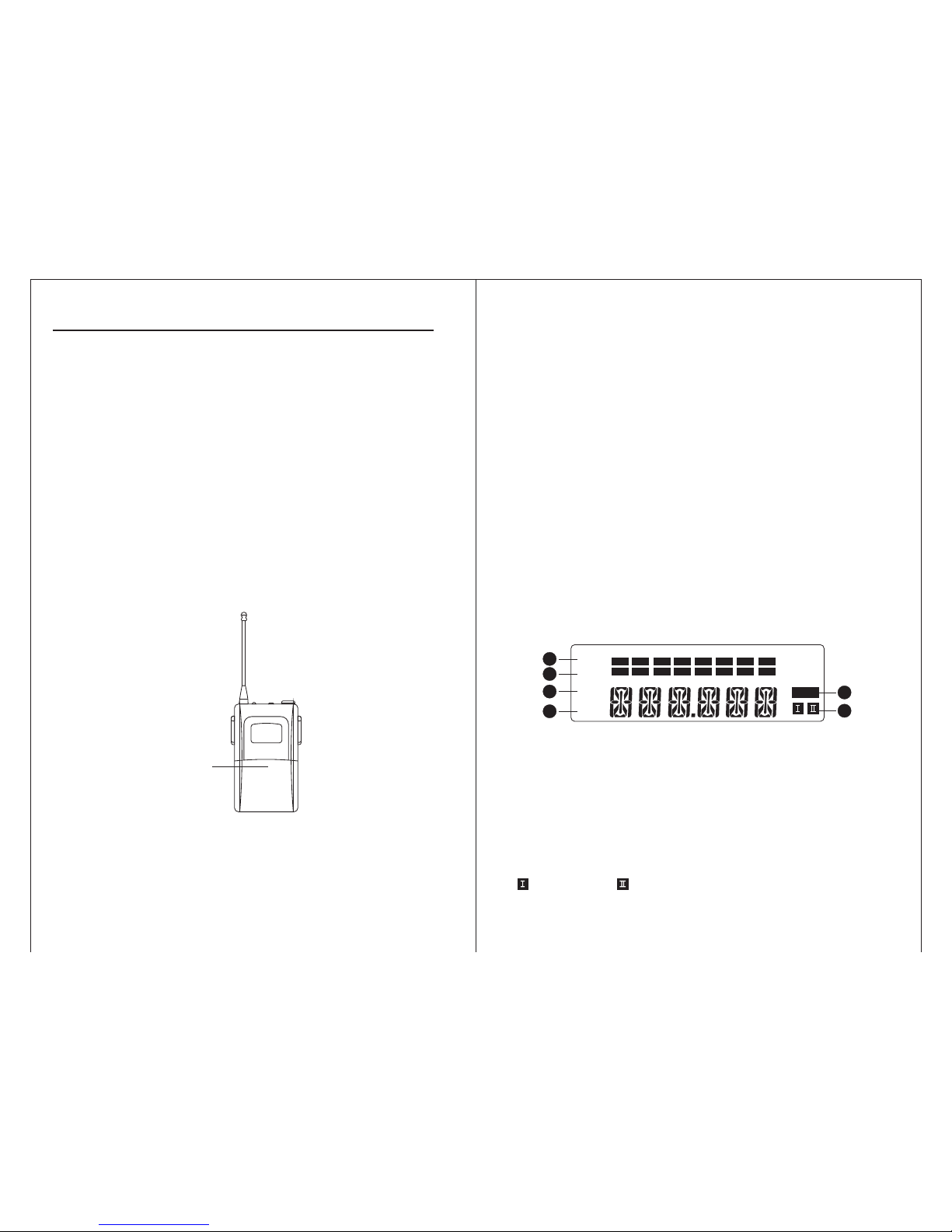
Introduction for the LCD of the receiver
6. power socket: DC 12V 500mA power inputs socket, central electrode of the socket
connects to positive pole.
7. antenna jack
8.noise elimination control: counter clock wisely, to turn down receive-sensitivity,
zoom in receive-distance, but strengthen anti-jamming function, rice versa.
9. audio balance out: suitable for long-distance connection, capable to knock down
the noise caused by line-connection.
10. audio mix out: send out one mixed signal by two.
-4-
1. 8-level RF display: signal strength of the receiving frequency
2. 8-level AF display: signal strength of the audio frequency
3. frequency menu display: when the indicator is on, current service frequency is
show by the last 6 digits
4. channel menu display: when the indicator is on, current service channel is shown.
5. mute display: when the indicator is on, frequency signal is not received.
6. channel display: dynamic display for the current auto-selected atenna channel,
shows channel A, means channel B.
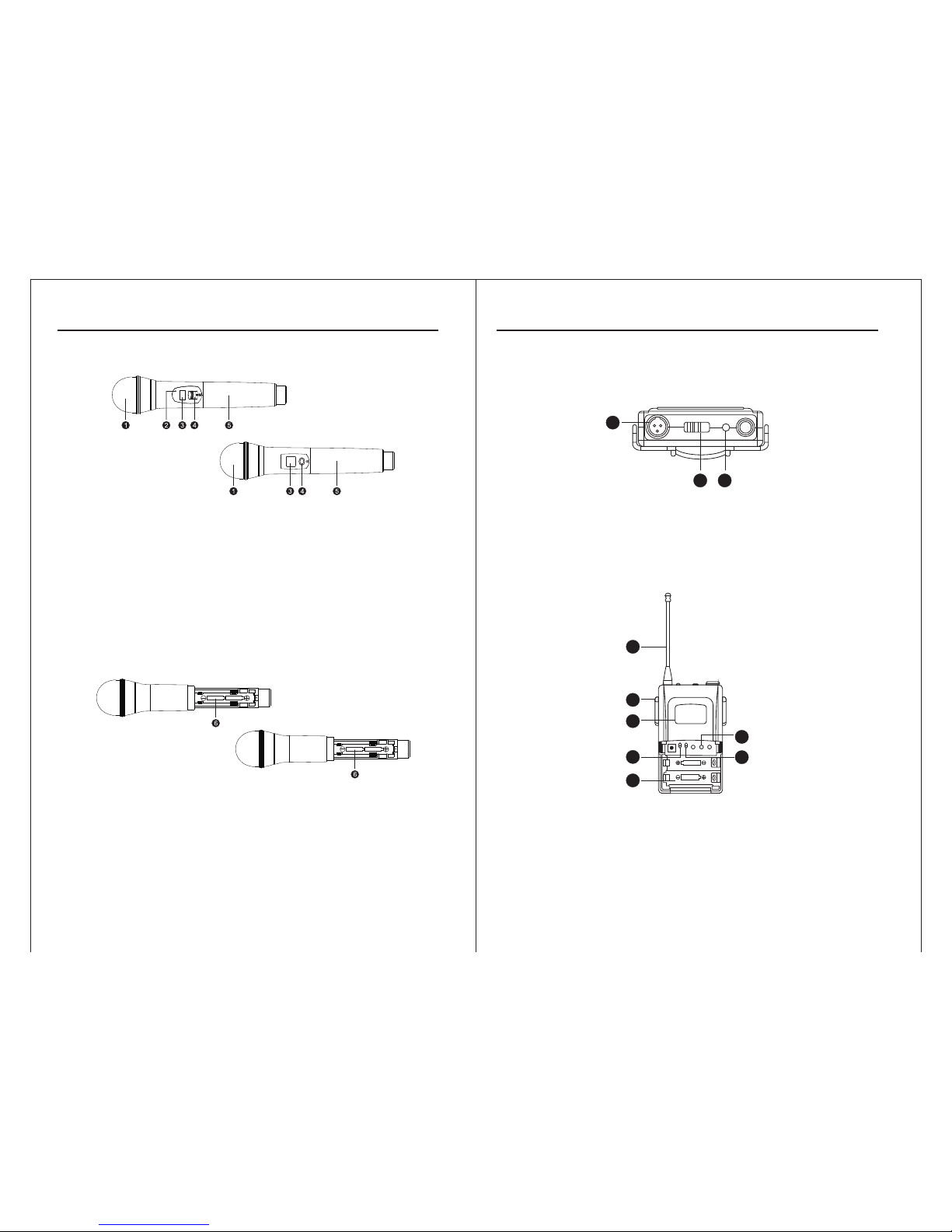
1. Sound receiver: steel netting and sound head module
2.
LCD: service channel and battery
Lnfrared channel selecting window: send the channel parameter to transmitter,
working in the "SET" key of the receiver
3.
4. 3-step on-off: turned-off goes downwards, mute stays middle, turned-on goes
upward.
Specifications of the hand mike
Introduction for the hand microphone
Caution: if you want the microphone works mute during in use, had better set
the switch at middle rather than turning off, Swit h downwards to turn c
off after use.
5. pipe body: out built batteries, emission circuit board, inbuilt transmitting antenna
after body
6. battery cage: 2 1.5V alkaline batteries (please take off the batteries, for not in use
a long time time)
-5-
Caution: case of several products being used in KV room, lower frequency is
recommtnded, less battery using and weaker radio-jamming)
1. input socket
2. power on-off: "ON" means power on, "OFF" means power off
3.indicator: when the switch goes to "ON", the indicator sparkles for once, which means
the battery works wen, if it has no flare, the battery is empty, or not yet well-set.
If the indicator is on at all time, the battery is running out.
ON OF F BATT
LOW
1
2 3
4
5
6
7
8
10
9
4. transmitting antenna: 1/4 wave lengh flagellifo m antenna.
5. clip: fix the mini mike some where on waist-side, can be revolved by 180 .
6. LCD: current service channel and battery volume.
r
°
functions of the lapel mike
Introduction of the lapel mike
-10-
A图
B图
A图
B图
Specifications of the handmike
-6-
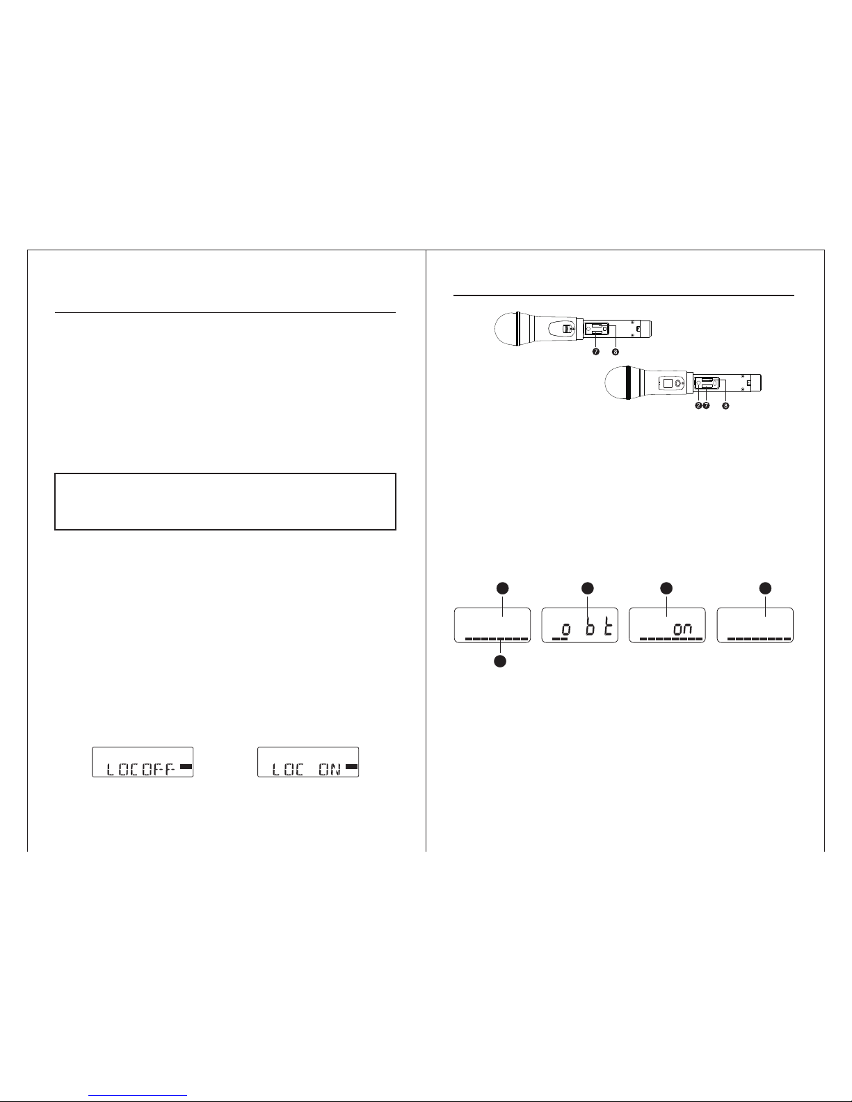
7. high-low RF switch (located inside the battery cage)
go to "ON", at the time outside power switch shaos off, the microphone is still
working at mute, but the transmitting mike remains transmitting state.
8. lock key (located in battery cage): used to lock the power on-off switch upwards
Caution: This switch is available to keeping non-professional from shutting
down the mike by mistake channing in use (because unexpected
turned-off causes 2-3 sec delay)
Introduction of hand mike LCD
B AT
028 C
H
B AT
L a
B AT
LOC
B AT
OFF
1
2
3 4 5
(图 1) (图 2) (图 3) (图 4)
1. channel display: current service channel
2. 8-level battery volume display: when the last 2-level starts displaying, full battery
is required.
3. please put on full-changed battery when display as pic·2.
4. when lock key is on with power switch off, display, as pic·3, which means
transmitter is locked, mute function is on while power off
Receiving machine channel -selecting and other special
functions of the the receiver.
-9-
* switch frequency display to channel display
1. turn on the powder of the receiving machine: press the powder button and LCD
light is bright
2. Press "SET" button for once, appear picture 8
4. Press" SET" to ensure, finish the funlation of unlocking.
3. Press " " button, appear picture T and flash
▲
RF
AF
5
-30 -25 -20 -15 -10 -5 0 PEAK
10 15 20 25 30 35 40
MUTE
M
H
Z
(图 7) (图 8)
RF
AF
5
-30 -25 -20 -15 -10 -5 0 PEAK
10 15 20 25 30 35 40
MUTE
M
H
Z
▲
1. turn on the powder of the receiving machine: press the powder button the LCD
light is bright.
2. Press "SET" continu ously for tuile. Show it picture 4
3. Press " " button, appear "picture 3" and flash
4. Press" SET" to ensure, press it again and than it will leture to the situation of
frequency display.
* lock the choosen channel
This locked funcation can be used when the leceiving machine is adjusted.
when the locked funcation is on, hte three funcation buttoin in the leceiving
machine ponel would be locked, in order to prevent inonprofessional presons
mistake work.
Operortion steps below:
1. turn on the power of receiving mochine: press the power button, LCD light is bright.
2. Press "SET" continuously for three times, appear picture 7
3. Press the " " button to ensure and finish the fucation of locked channel.
▲
* turn off the locked funcation
A图
B图

-7-
Specifications of the hand mike
manual for handheld transmitter
channel battery volume. If service channel needs to change, receiver's channel
should be changed firs ly. then aim up the infrared windows of transmitter and t
receiver, and then operate channel-selecting by hitting "SET" in receiver, klew channel
para meters will be sent to the transmitter.
manual for handheld transmitter
1. hold the column on upside, press he battery cover on upside, which is found right t
below the sphere protect-net slide down the battery cover, the battery cage will expose.
Caution: do not misset polarities, it may alamage internal electronic components
of transmitter
2. Put two new 1.5V alkaline battery on. make sure polarities are well set
5 10 15 20 25 30 35 40
-30 -25 -15 -10 -5 0 PEAK-20
RF
AF
CHAN.
MUTE
M
H
Z
5 10 15 20 25 30 35 40
-30 -25 -15 -10 -5 0 PEAK-20
RF
AF
FREQ.
CHAN.
MUTE
M
H
Z
5 10 15 20 25 30 35 40
-30 -25 -15 -10 -5 0 PEAK-20
RF
AF
FREQ.
CHAN.
MUTE
M
H
Z
(图 4) (图 5)
(图 6)
(图 1) (图 2)
(图 3)
5 10 15 20 25 30 35 40
-30 -25 -15 -10 -5 0 PEAK-20
RF
AF
CHAN.
MUTE
M
H
Z
5 10 15 20 25 30 35 40
-30 -25 -15 -10 -5 0 PEAK-20
RF
AF
CHAN.
MUTE
M
H
Z
5 10 15 20 25 30 35 40
-30 -25 -15 -10 -5 0 PEAK-20
RF
AF
CHAN.
MUTE
M
H
Z
Channel-selecting and other special functions of the receiver
-8-
select channel autometically with infrared
1. turn on he receiver: press the power on-off and hold on till LCD lights up.t
the selection.
3. turn on the mike, press "SET", LCD will display like pic·1, then aim the channel-
selecting window of the mike of ACT □ window of the receiver, till LCD displays
like pic·2, channel is well-selected.
4. display like pic·3, which means infrared is sent but not yet selected by any channel,
Switch channel display to frequency display
1. turn on he receiver: press the power on-off and hold on till LCD lights up.t
2. press "SET" twice, display like pic·4.
4. press "SET" to ensure, press again, go back to frequency display state, like pic·6.
2. select channel (or frequency) by pressing " " or " "then press "SET" to ensure
▲
▲
so press " " to select channel one more time.
▲
3. press " " ,sparkle like pic·5.
▲

FCC Statement
Changes or modifications not expressly approved by the party responsible
for compliance could void the user's authority to operate the equipment.
This equipment has been tested and found to comply with the limits for a
Class B digital device, pursuant to Part 15 of the FCC Rules. These limits
are designed to provide reasonable protection against harmful interference
in a residential installation. This equipment generates uses and can radiate
radio frequency energy and, if not installed and used in accordance with the
instructions, may cause harmful interference to radio communications.
However, there is no guarantee that interference will not occur in a
particular installation. If this equipment does cause harmful interference to
radio or television reception, which can be determined by turning the
equipment off and on, the user is encouraged to try to correct the
interference by one or more of the following measures:
-- Reorient or relocate the receiving antenna.
-- Increase the separation between the equipment and receiver.
-- Connect the equipment into an outlet on a circuit different from that to
which the receiver is connected.
-- Consult the dealer or an experienced radio/TV technician for help
This device complies with part 15 of the FCC rules. Operation is subject to
the following two conditions (1)this device may not cause harmful
interference, and (2) this device must accept any interference received,
including interference that may cause undesired operation
Table of contents


