2
LIMITED WARRANTY
Your Little Giant product is guaranteed to be in perfect condi-
tion when it leaves our Factory. It is warranted against defective
materials and workmanship for a period of 12 months from date
of purchase by the user. Any product that should fail for either of
the above two reasons and is still within the warranty period, will
be repaired or replaced if returned prepaid to our Factory. For
our customers in the CONTINENTAL UNITED STATES: Please
return the defective unit, postage paid, to the factory at 301 North
MacArthur Blvd., Oklahoma City, OK 73127-6616. All defective prod-
ucts returned under warranty will be fully inspected to determine
“CAUSE OF FAILURE” before any warranty is approved. Little
Giant will honor the warranty within the warranty time period
specified on satisfactory written proof of purchase.
DISCLAIMER: Any oral statements about the product made by the
seller, the manufacturer, the representatives or any other parties, do
not constitute warranties, shall not be relied upon by the user, and
are not part of the contract for sale. Seller’s and manufacturer’s
only obligation, and buyer’s only remedy, shall be the replacement
and/or repair by the manufacturer of the product as described
above. Neither seller nor the manufacturer shall be liable for any
injury, loss or damage, direct, incidental or consequential (including,
but not limited to, incidental or consequential damages for lost
profits, lost sales, injury to person or property, or any other incidental
or consequential loss), arising out of the use or the inability to use
the product, and the user agrees that no other remedy shall be
available to it. Before using, the user shall determine the suitability
of the product for his intended use, and user assumes all risk
and liability whatsoever in connection therewith. THE WARRANTY
AND REMEDY DESCRIBED IN THIS LIMITED WARRANTY IS AN
EXCLUSIVE WARRANTY AND REMEDY AND IS IN LIEU OF ANY
OTHER WARRANTY OR REMEDY, EXPRESSED OR IMPLIED,
WHICH OTHER WARRANTIES AND REMEDIES ARE HEREBY
EXPRESSLY EXCLUDED, INCLUDING, BUT NOT LIMITED TO
ANY IMPLIED WARRANTY OF MERCHANTABILITY OR FITNESS
FOR A PARTICULAR PURPOSE. Some states do not allow the
exclusion or limitation of incidental or consequential damages, so
the above limitation or exclusion may not apply to you. This war-
ranty gives you specific legal rights, and you may also have other
rights which vary from state to state.
Warranty will be VOID if any of the following conditions are found:
1. Product connected to voltage other than indicated on name-
plate.
2. Product abuse by customer.
3. Product used in a corrosive environment.
4. Product was used other than intended as described in the
introduction of this Installation Guide.
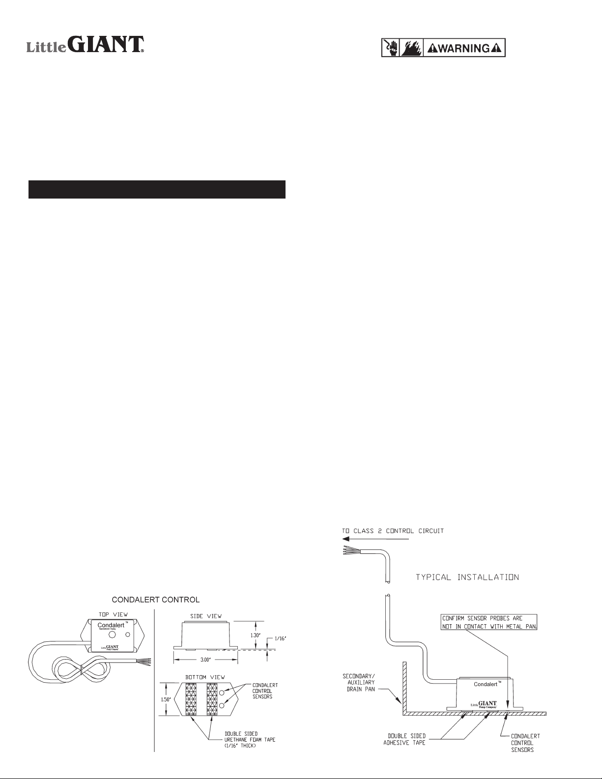
If you do not have a drain pan, place the Condalert under or
near the air handler where condensate over flow will collect. A
water stain from a previous over flow marks a good location.
CAUTION: CONFIRM CONDALERT CONTROL SENSORS ARE
NOT IN CONTACT WITH SURFACE.
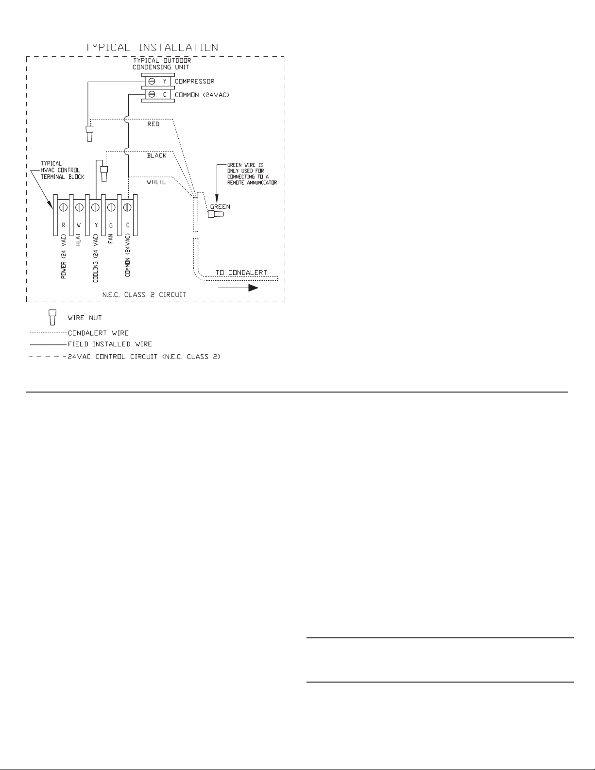
Connect Control Wires
3. Locate the two 24 VAC low voltage control wires that run from the
air handler, out to the condensing unit (See Figure 3 for Typical
Installation Wire Diagram). Carefully strip off the outer cable
insulation and cut the 24 volt cooling control wire then make the
“black” and “red” connections per Figure 3. The cut wire that
comes from the air handler must connect to the “black” wire
of the Condalert. The cut wire that goes to the condensing unit
must connect to the “red” wire of the Condalert. The “white” wire
from the Condalert connects to the remaining common 24 volt
wire that was not cut. It is recommended to put a delay on make
timer on condenser contactor coil to prevent short cycling. The
“green” wire from the Condalert is used for a remote annuncia-
tor installation. If you are not using a remote annunciator, do not
make any connections to the “green” wire.
4. Turn on power to the air handler and the condensing unit. Set
the thermostat to call for the air conditioner to start. Check that
the air handler and condensing unit are both operating. Place
the Condalert Control Sensors onto a wet paper towel. The
sensors are 2 stainless steel pins located on the bottom of the
Condalert Control box. The Condalert will go into alarm condi-
tion when the sensors are wet. The red LED will illuminate and
the buzzer will sound (buzzer model only). Check to see that
the condensing unit is shut down and the air handler fan is still
running. After test, dry off the Condalert probes on the bottom
of the unit. Finally attach the Condalert Control to the secondary
pan with the double sided tape if you require.
Figure 3
Form 998612 - 04/2006
©2008 Franklin Electric Co., Inc.
Little Giant® is a registered trademark of Franklin Electric Co., Inc.
For parts or repair, please contact . . . . . . . . . . . . . . . . . . . . 1.888.572.9933
For technical assistance, please contact . . . . . . . . . . . . . . . 1.888.956.0000
www.LittleGiantPump.com