manuals.online logo
Brands
  1. Home
  2. •
  3. Brands
  4. •
  5. EMS
  6. •
  7. Recording Equipment
  8. •
  9. EMS EC-63-0001 User manual

EMS EC-63-0001 User manual

SOUNDERS FAU LT ZONE/RESET
EOL L1 L2 EOL L1 L2 ALARM
RES EOL L1 L2
1 Introduction
6 Connection wiring
2 Pre installation
Part no Product description
EC-63-0001 EMS Conventional Interface Card
Conventional Interface Card (CIC)
Installation Guide
3 Connect CIC to the ZIM
5 Fasten the ZIM’s terminals
SOUNDERS FAULT ZONE/RESET
EOL L1 L2 EOL L1 L2 ALARM
RES
EOL L1 L2
(+) (-) (+) (-) (+) (-) (+) (-) (+) (-) (+) (-) (+) (-)
SOUNDERS FAU LT ZONE/RESET
EOL L1 L2 EOL L1 L2 ALARM
RES EOL L1 L2
The CIC can be wired in two different ways.
Fault notification can either be monitored via the conventional
fire panel’s sounder or zone circuit.
See overleaf for the alternative wiring methods.
Ensure the pins line up with the ZIM’s terminal connections as
shown.
!
Installation must conform to applicable local installation
codes and
should only be installed by a fully trained
competent person.
Only fit the CIC to the zone interface module (ZIM), when
connecting to a conventional fire panel.
The CIC should only be connected to designated zone and
sounder circuits.
Refer to the EMS wireless zone monitor engineers guide
(TSD143) for full programming information.
Refer to the conventional control panel compatibility document
(MK58) for details of compatible conventional fire alarm panels.
This device contains electronics that may be susceptible to
damage from electrostatic discharge (ESD). Take appropriate
precautions when handling electronic boards.
ZIM with
CIC fitted WZM
www.emsgroup.co.uk
RadioDetectorBase
PRESSHERETO
LOGON
IDENT
FireCell wireless devices
POWER
FAULT
WIRELESSZONEMONITOR
FC-ZIM-001
Conventional
fire panel
The conventional interface card (CIC) when fitted to the zone
interface module (ZIM), enables 30 FireCell wireless devices to be
added to an existing conventional fire panel, via a wireless zone
monitor (WZM).
*
*Designated zone
and sounder circuits.
4 Fasten the CIC PCB into the ZIM
©2021 EMS Ltd. All rights reserved Page 1 of 2 TSD147-99 Iss 6 15/12/2021 AJM
Manufacturer Carrier Manufacturing Polska Sp. Z o.o. Ul.
Kolejowa 24. 39-100 Ropczyce, Poland
Year of manufacture See devices serial number label
Certification
Certification body
CPR DoP 0359-CPR-00436
Approved to EN54-18:2005. Fire detection and fire alarm
systems.
Part 18: Input/output devices.
European Union
directives
TX
RADIO
WD
RESET
HELP
RX
ON
1 2 3 4 5 6 7 8
BACK
POWER
FAULT
ISOLATE
SCR
+
-
LOOPIN
SCR
LOOPOUT
+
-
12 3 4 5 6 7
3V3
TX
RX
0V
Operating temperature -10 to +55 °C
Storage temperature 5 to 30 °C
Humidity 0 to 95% non-condensing
Supply Powered from the zone interface monitor
Current drawn from
connected panel (max.) 6 mA
Voltage (max.) 50 VDC
IP rating IP65
(when fitted inside zone interface monitor)
Dimensions (W x H x D) 110 x 50 x 10 mm
Weight 0.05 kg
Location Type A: For indoor use
TX
RADIO
WD
RESET
HELP
RX
ON
1 2 3 4 5 6 7 8
BACK
POWER
FAULT
ISOLATE
SCR
+
-
LOOPIN
SCR
LOOPOUT
+
-
12 3 4 5 6 7
3V3
TX
RX
0V
OUTPUT 2OUTPUT 1
3VDC SET RST
INPUT1 INPUT2
LED
ENABLE
POWER
INPUT 1
INPUT 2
FAULT
CLOSED
0 1
1
64
F-SAFE
N/O COM N/C
SERIALNO
LOGON
IP- IP+ IP- IP+
3VDC SET RST N/O COM N/C
EXPAN1 EXPAN2
RELAYON
RELAYON
2
4
8
16
32
ANTENNA
KEEPCABLES AWAYFROM THIS AREA
SOUNDER FAULT ZONE
EOL L1L2 EOL L1L2 ALARM
RES
EOL L1L2
(+) (-) (+) (-) (+) (-) (+) (-) (+) (-) (+) (-) (+) (-)
SOUNDERS FAULT ZONE/RESET
EOL L1 L2 EOL L1 L2 ALARM
RES
EOL L1 L2
(+) (-) (+) (-) (+) (-) (+) (-) (+) (-) (+) (-) (+) (-)
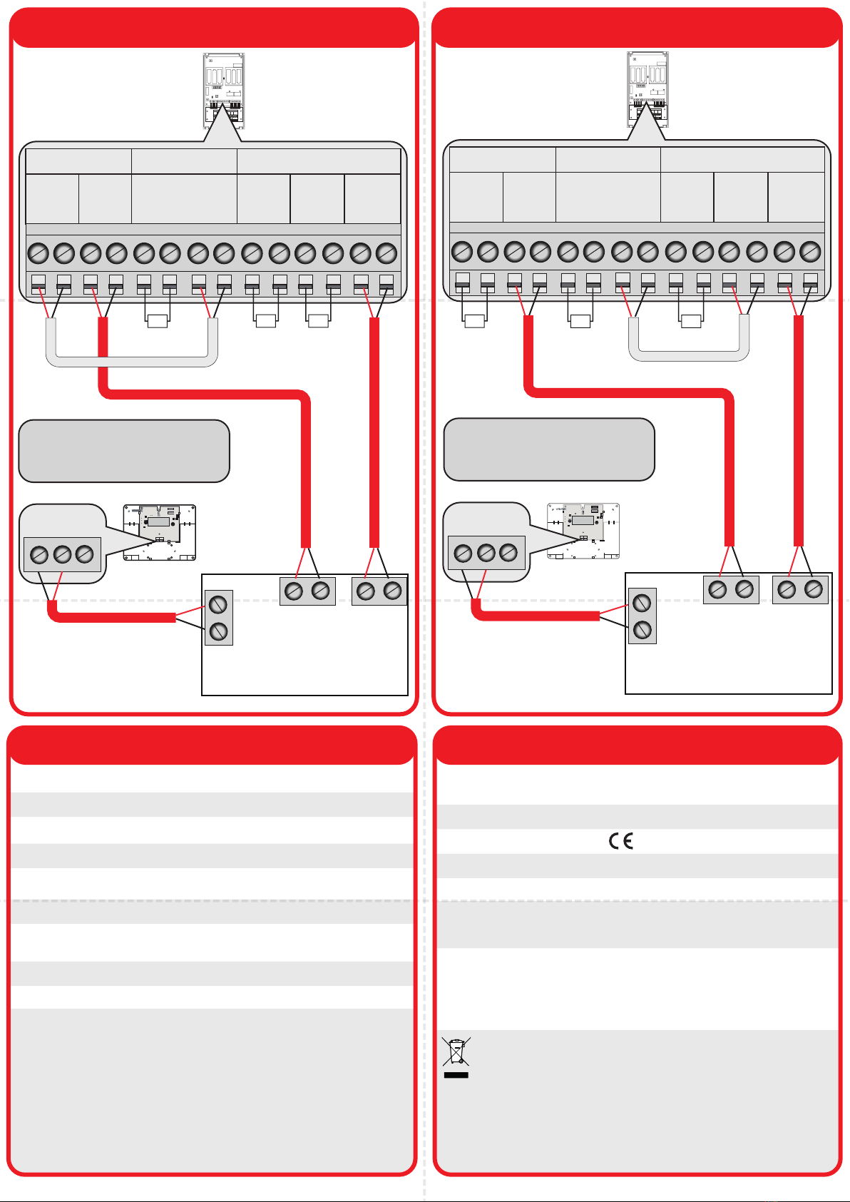
6 Connection wiring continued
LOOP IN
24V OUT
- +
SOUNDER
+ -
ZONE
+ -
+ -
+ -
13
2
1= Sounder circuit EOL resistor
2= Alarm triggering resistor
3= Zone circuit EOL resistor
6 Connection Wiring continued
Option 1
Wired to provide fault
notification on the
conventional fire panel’s
SOUNDER CIRCUIT
Option 2
Wired to provide fault
notification on the
conventional fire panel’s
ZONE CIRCUIT
OUTPUT 2OUTPUT 1
3VDC SET RST
INPUT1 INPUT2
LED
ENABLE
POWER
INPUT 1
INPUT 2
FAULT
CLOSED
0 1
1
64
F-SAFE
N/O COM N/C
SERIALNO
LOGON
IP- IP+ IP- IP+
3VDC SET RST N/O COM N/C
EXPAN1 EXPAN2
RELAYON
RELAYON
2
4
8
16
32
ANTENNA
KEEPCABLES AWAYFROM THIS AREA
SOUNDER FAULT ZONE
EOL L1L2 EOL L1L2 ALARM
RES
EOL L1L2
(+) (-) (+) (-) (+) (-) (+) (-) (+) (-) (+) (-) (+) (-)
SOUNDERS FAULT ZONE/RESET
EOL L1 L2 EOL L1 L2 ALARM
RES
EOL L1 L2
(+) (-) (+) (-) (+) (-) (+) (-) (+) (-) (+) (-) (+) (-)
LOOP IN
24V OUT
- +
SOUNDER
+ -
ZONE
+ -
13
2
1= Sounder circuits EOL resistor
2= Zone circuits EOL resistor
3= Alarm triggering resistor
14
0905
Zone interface
monitor (ZIM)
with conventional
interface card
(CIC) fitted
Zone interface
monitor (ZIM)
with conventional
interface card
(CIC) fitted
Conventional
re panel
Conventional
re panel
Wireless
zone
monitor
(WZM)
Wireless
zone
monitor
(WZM)
Specification Regulatory information
EMS declares that this device is in compliance
with Directive 2014/53/EU. The full text of
the EU declaration of conformity is available
at the following internet address:
www.emsgroup.co.uk
2012/19/EU (WEEE directive):
Products marked with this symbol cannot be
disposed of as unsorted municipal waste in
the European Union. For recycling, return
this product to your local supplier upon
purchase of equivalent new equipment, or
dispose of it at designated collection points.
For more information see
www.recyclethis.info
©2021 EMS Ltd. All rights reserved Page 2 of 2 TSD147-99 Iss 6 15/12/2021 AJM

Other EMS Recording Equipment manuals

EMS EC-63-0001 User manual

EMS

EMS EC-63-0001 User manual

EMS CPC-PCIe User manual

EMS

EMS CPC-PCIe User manual

EMS CPC-PP User manual

EMS

EMS CPC-PP User manual

Popular Recording Equipment manuals by other brands

Ampex ATR-700 Operation and maintenance manual

Ampex

Ampex ATR-700 Operation and maintenance manual

Tascam Mixcast 4 owner's manual

Tascam

Tascam Mixcast 4 owner's manual

Arbiter Systems 1133A Operation manual

Arbiter Systems

Arbiter Systems 1133A Operation manual

Yamaha MDR-1 Handling instructions

Yamaha

Yamaha MDR-1 Handling instructions

Crestron PSPHD Operation guide

Crestron

Crestron PSPHD Operation guide

oventrop Regtronic S-Bus Installation and operating instructions

oventrop

oventrop Regtronic S-Bus Installation and operating instructions

SMC Networks EX250-SDN1 Operation manual

SMC Networks

SMC Networks EX250-SDN1 Operation manual

JGC JGC-RRMP-6770 user manual

JGC

JGC JGC-RRMP-6770 user manual

ABB IP Touch 7 manual

ABB

ABB IP Touch 7 manual

Tekbox TBS06 manual

Tekbox

Tekbox TBS06 manual

Ekinex EK-EH2-TP quick start guide

Ekinex

Ekinex EK-EH2-TP quick start guide

Emerson PACSystems Versamax Important product information

Emerson

Emerson PACSystems Versamax Important product information

weintek cMT2108X Series Installation instruction

weintek

weintek cMT2108X Series Installation instruction

JVC XL-R5000BK Service manual

JVC

JVC XL-R5000BK Service manual

Mackie HDR 24 quick start guide

Mackie

Mackie HDR 24 quick start guide

Behringer ULTRA-DI PRO DI800 Technical specifications

Behringer

Behringer ULTRA-DI PRO DI800 Technical specifications

Extron electronics Extron IPL T S4 Setup guide

Extron electronics

Extron electronics Extron IPL T S4 Setup guide

Thermo Scientific UCI-100 operating instructions

Thermo Scientific

Thermo Scientific UCI-100 operating instructions

manuals.online logo
manuals.online logoBrands
  • About & Mission
  • Contact us
  • Privacy Policy
  • Terms and Conditions

Copyright 2025 Manuals.Online. All Rights Reserved.