EMSI TENS-6000 User manual
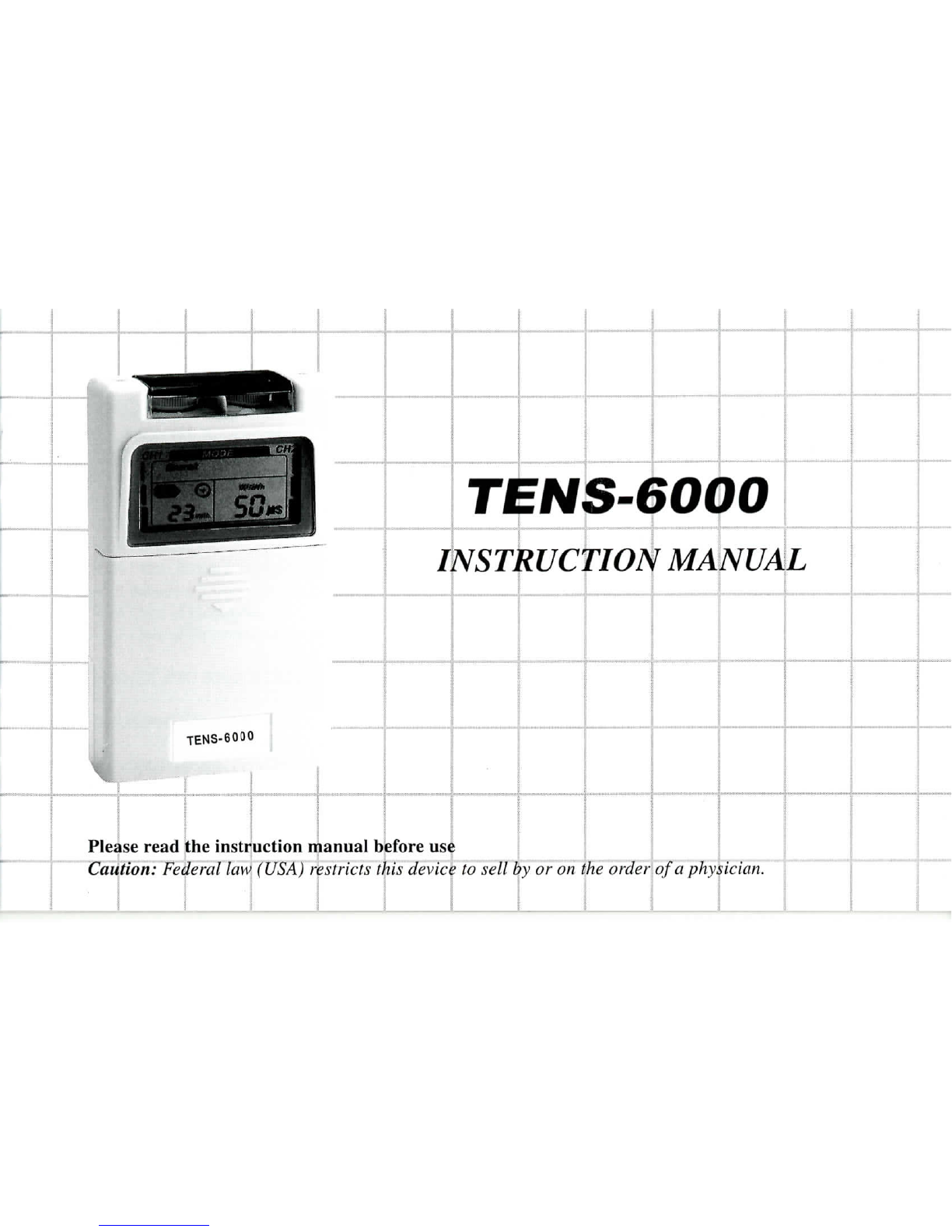
TENS-6000
INSTRUCTION
MANUAL
•El
TENS-6000
Pleaseread
the
instruction
manualbefore
u:
Caution: Federal
law
(USA) restricts this device
to
sell
by or on
the
order
of
a
phy

Contents
Chapter
Page
I
INTRODUCTION
I.
i
General
information
I
1.2
Indications
foruseI
1.3
Warnings
I
1.4
Precautions
2
1.5
AdverseReactions
3
PRODUCT
DESCRIPTIONS
2.1
Front
and
Rear
Panel
.4-6
STIMULATION
MODES
7-9
INSTRUCTIONS
FORUSE
4.1
Check
Battery
10
4.2
Connect
electrodes
to
leadwires
II
4.3
Connect
leadwires
to
unit
12
4.4
Place
electrodes
on
skin
13
4.5
Adjust
Output
13
4.6
Select
the
mode
14
Chapter
Page
4.7
Adjust
the
Pulse
Rate
14
4.8
Adjust
the
Pulse
Width
15
4.9
Adjust
Timer
15
4.10
AdjustChannelAmplitude
15
4.
II
Turn
Unit
Off
,
17
4.12
PatientCompliance
Timer
17
4.1
3
Portability
20
4.14
"
Low
Battery
"
indicator
, 20
4.15
Battery
21
4.16
Care
of
Electrodes
21
4.17
Care
of
Electrodecords
21
5
HANDLING
AND
STORAGE
22
6
SPECIFICATION
22
7
ACCESSORIES
23
8
TROUBLESHOOTING
24

/.
INTRODUCTION
I.I
Generalinformation:
ThisTENS
isa
lightweight
and
portable
medicaldevice,
which
can
help
to
reduce
the
pain
and
discomfort.
It
utilizes
the
low
electric-current
to
stimulatemuscle nerve
to
achieve
the
symptomaticrelief
of
chronicintractablepain,
post-traumatic
and
post-surgicalpain.
1.2.
Indications
for
use:
This
device
is
used
in
symptomaticrelief
of
chronicintractablepain,post-traumatic
and
post-surgicalpain.
1.3
Warnings:
1.3.1
The
long-term
effects
of
chronicelectricalstimulation
are
unknown.
1.3.2
Stimulation should
notbe
appliedover
the
carotid
sinus
nerves,particularly
in
patients
with
a
known
sensitivity
tothe
carotid
sinus
reflex.
1.3.3
Stimulation
should
notbe
appliedover
the
neck
or
mouth.
Severe
spasm
ofthe
laryngeal
and
pharyngeal
muscles
may
occur
andthe
contractions
may
occur
andthe
contractions
maybe
strong
enough
to
close
the
airway
or
cause
difficulty
in
breathing.
1.3.4
Stimulationshould
notbe
appliedtransthoracically
in
that
the
introduction
of
electricalcurrent
into
the
heart
may
cause
cardiacarrhythmias.
1.3.5
Stimulationshould
notbe
appliedoverswollen,infected,
or
inflamed
areas
or
skin
eruptions,
e.g.,
phlebitis,
thrombophlebitis,
varicoseveins,etc.
1.3.6
Stimulation
should
notbe
applied
over,
orin
proximity
to,
cancerous
lesions.
1.3.7
For
external
use
only.
1.3.8
Donotuse
TENS
ontheeye
area.
1.3.9
Thisdeviceshould
be
usedonlyunder
the
continuedsupervision
ofa
physician.
1.3.10
Safety
of
TENSdevices
foruse
during
pregnancy
or
delivery
hasnot
beenestablished.
1.3.11
Electronicequipment
such
asECG
monitors
andECG
alarms
maynot
operate
properly
whenTENS
isin
use.
1.3.12
Apply
the
electrodes
to
clean,
dryand
unbrokenskinonly.
1.3.13
Thisdeviceshould
notbe
used
while driving,operatingmachinery,
or
during
any
activity
in
which
involuntary musclecontractions
mayputthe
user
at
undue risk
of
injury.
1.3.14
Thisdeviceshould
be
kept
outofthe
reach
of
children.
1.4
Precautions:
1.4.1
Cautionshould
be
used
for
patients
with
suspected
or
diagnosedheartproblems.
1.4.2
Cautionshould
be
used
for
patients
with
suspected
or
diagnosed
epilepsy.
1.4.3
Cautionshould
be
used
inthe
presence
ofthe
following:
(a)When
there
isa
tendency
to
hemorrhage
following
acutetrauma
or
fracture;
(b)Following
recent
surgicalprocedureswhenmuscle
contraction
may
disrupt
the
healingprocess.
(c)Over
the
menstruating
or
pregnantuterus;
and
(d)Over
areas
ofthe
skinwhich
lack
normalsensation.
1.4.4
Somepatients
may
experienceskin
irritation
of
hypersensitivity
duetothe
electricalstimulation
or
electrical
conductivemedium.
The
irritation
can
usually
be
reduced
by
using
an
alternateconductivemedium,
or
alternate
electrode
placement.

1.4.5
Electrodeplacement
and
stimulationsettingsshould
be
based
onthe
guidance
ofthe
prescribing
practitioner.
1.4.6
Thisdeviceshould
be
used
only
with
the
leads
and
electrodesrecommended
forusebythe
manufacturer.
1
.4.7
Isolated
cases
of
skin
irritation
may
occur
atthe
site
ofthe
electrodeplacement
following
long-term
application.
1.4.8
Effectiveness
is
highlydependentuponpatient
selection
bya
personqualified
inthe
management
of
pain
patients.
1.4.9
Ifthe
stimulation
levels
are
uncomfortable
or
becomeuncomfortable,reduce
the
stimulationamplitude
toa
comfortable
level
and
contact
your
physician
if
problemspersist.
1.5
Adverse
Reactions:
1.5.1
Possible
skin
irritation
or
electrode
burn
under
the
electrodes
may
occur.
1.5.2
Possible
allergicskinreaction
to
tape
orgelmay
occur.
3
2.
PRODUCT
DESCR/PT/ONS
Z.I
none
ana
ncnr
pnnci,
'|0p
View
""—
">
Knob
Cover
Channl
1
On/Off
and.
Channl
2
On/Off
and
Front
View
j
jB
1^1
\
Knob
Cover
Channl
1
Output
^
R^lde""™'
^s^
Receptacle
Kecepiacie
Amplitude
Knob
^^K^^^^^
Battery
Indicator
Mode-.
'
yA
Back
View
Knob
Cover
Channl
Output
—
^^j-vMiaiMHJtt
Pulse
Rate
.__£^1,
A
i
^~~
clip
Decrease
Button
^
//
^"
\t
Button
-/
^
Mode
Button
*
*
Lid
Cover
' ' j
;
"
1
Battery
Cover
it
nil""
i"
—
"
—
1

Knob
Cover:
An
acrylic
knob
cover
can
protect
from
touching
Amplitude
Controls
when
the
unit
is
used.
After
adjusting
the
output,
remember
to
have
the
coverclosed.
Lid
Cover:
A
panelcovers
the
controls
for
Mode,Set,INCREASE
and
DECREASE
Adjusting.Yourmedicalprofessional
mayask
toset
these
controls
foryouand
request
that
you
leave
the
cover
in
place.
Amplitude
Controls:
It
controls
the
"INTENSTITY"
level
of
stimulating
pulses.
Thesecontrolslocated
atthetopofthe
unit
regulate
the
amplitude,
or
intensity,
ofthe
stimulation
andarethe
ON/OFF
CONTROL
TheON
indicator
light
will
stay
litas
long
asthe
unit
is
working,
and
mimics
the
output
ofthe
electricalpulse.
Caution:
If the
stimulation
levels
are
uncomfortable
or
become uncomfortable, reduce
the
stimulation
intensity
to a
comfortable
level
and
contact
your
physician
if
problems
persist.
"INCREASE"
increace
control
button
(using
a
triangle-button)
This
button
will
carry
the
increasecharacter
to
increase
the
pulse
width
from
50~300us,
andto
increase
the
pulse
rate
from
2 to
ISOHz,
andto
increase
the
timer
from
5 to90
mins
to
continuousmode.
"DECREASE"
decrease
control
button
(using
a
invertedtriangle-button)
This
button
will
carry
the
decrease
character
to
decrease
the
pulse
width
from
300~50us,
andto
decrease
the
pulse
rate
from
ISO
to
2Hz,
andto
decrease
the
timer
from
continuous mode
to90to5
min.
"MODE"
button
(using
a
round-button
onthe
right
side
ofthe
control
panel)
This
button
willcarry
the
character
to
select
fora
Stimulation-Mode.
It
offers
the
modestatus
from
fivetype
of
stimulationmodes,which
are
Burst,
Normal,
MRW(Modulated
Rate
and
Width),
SD(Strengh
Duration)
and
Bi-Pulse.
"SET"
button
(using
a
round-button
onthe
middle
ofthe
control
panel)
This
button
will
carry
the
character
tosetthe
rate,
width
and
timer.Users
press
the
"SET"
button
to
enter
a
parametersettingmodeincludingrate,width
and
timer.
LCD
screen
This
LCD
will
be
utilized
to
display
stimulating
mode/
pulse
width/
pulse
rate
andto
display
timer.
The
channel
output
will
be
indicated
onthe
leftside(Channel
I)
and
right
side
(Channel
2)oftheLCD
screen.
The
modes
will
be
showed
onthetopoftheLCD
panel.
The
pulse
rate
and
width
will
be
showed
onthe
middle-right
ofthe
screen.
The
timer
and
clocksymbol
are
showed
onthe
middle-right
ofthe
screen,
the
clocksymbol
will
flash
in
final
5
min.
Battery
compartment
9
Voltage
battery-
I pc
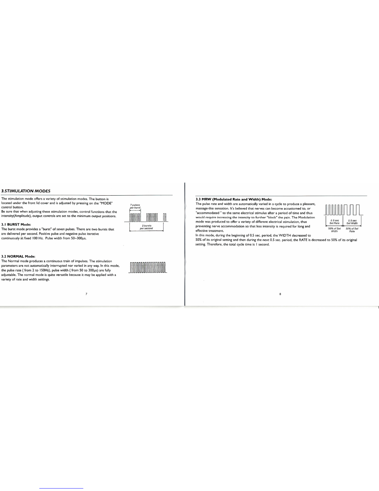
3.STJ/V1ULAT/ON
MODES
The
stimulationmodeoffers
a
variety
of
stimulationmodes.
The
button
is
locatedunder
the
front
lid
cover
andis
adjusted
by
pressing
onthe
"MODE"
control
button.
Be
sure
that
whenadjustingthesestimulationmodes,
control
functionsthat
the
intensity(Amplitude),
output
controls
aresettothe
minimum
output
positions.
3.1
BURST
Mode:
The
burst
modeprovides
a
"burst"
of
sevenpulses.There
aretwo
bursts
that
are
delivered
per
second.Positivepulse
and
negative
pulse
iterative
continuously
at
fixed
100
Hz.
Pulse
width
from
50~300us.
3.2
NORMAL
Mode:
The
Normal
modeproduces
a
continuoustrain
of
impulses.
The
stimulation
parameters
arenot
automatically
interrupted
nor
varied
inany
way.
In
thismode,
the
pulserate
(from
2 to
150Hz),
pulse
width
(from
50to
300us)
are
fully
adjustable.
The
normal mode
is
quiteversatile
because
itmaybe
applied
with
a
variety
of
rate
and
width
settings.
3.3
MRW
(Modulated
Rate
and
Width)
Mode:
The
pulse
rate
and
width
are
automaticallyvaried
ina
cycle
to
produce
a
pleasant,
massage-like
sensation.It'sbelievedthatnervescanbecomeaccustomedto,or
"accommodated
"
tothe
same
electricalstimulusafter
a
period
of
time
and
thus
wouldrequireincreasing
the
intensity
to
further
"block"
the
pain.
The
Modulation
mode
was
produced
to
offer
a
variety
of
differentelectricalstimulation,thus
preventingnerveaccommodation
so
that
less
intensity
is
required
for
long
and
'
7
H
£
effective
treatment.
In
thismode,during
the
beginning
of0.5
sec.period,
the
WIDTH
decreased
to
50%
ofits
original
setting
and
then
during
the
next
0.5
sec.
period,
the
RATE
is
decreased
to50%ofits
original
setting.Therefore,
the
total
cycle
time
isI
second.
0.5
sec
Set
Rate
O.Ssec
Set
Width
50%ofSet
Width
50%ofSet
Rate

6
seconds
3.4
SD
(Strength
Duration)
Mode:
Strength-Durationmodulation
consists
of
alternatingmodulatedintensity
and
pulse
width,
so
that
the
intensity
is
always
increasing
while
the
pulse
width
is
decreasing
and
vice-versa.
The
stimulationintensitymodulate
to
62.5%maximum
of
setting
(width
equal
to
setting).
The
pulse
width
modulate
to67%of
setting
(intensity
equal
to
setting).Total
cycle
time
is6
seconds.
Rate
(from
2~l50Hz),
width
(from
50~300us)
are
fully
adjustable.
3.5
Bi-Pulse
Mode:
Delivers
4
pulses
per
second
to
Channel
I
(i.e.
the
pulse
rate
of
Channel
I is
fixed
at
4 Hz)
while delivering
100
pulses
per
second
to
Channel2(i.e.
the
pulserate
of
Channel
2 is
fixed
at
100
Hz).Stimulation
is
burst
onfor
1.0
second,then
offfor
1.0
second.
There
illustration
each
pulse
as a
verticalline.
Pulse
width
(from
50~300us)
is
fully
adjustable.
NOTE:
Always
read this
instruction
manual beforeuse.
1sec.
(sec.
1sec.
4.
INSTRUCTIONS
FOR USE
PREPARATION
FORUSE
4.1
CheckBattery:
Proceed
to
insert
a fresh9V
alkaline
or
rechargeable
battery
into
the
batterycompartment.Makesure
that
youare
installing
the
batteriesproperly.
The
battery
is
inserted
inthe
casing
onthe
back
ofthe
stimulator
unit.
BE
SURE
TO
MATCH
THE
POSITIVE
AND
NEGATIVE ENDS
OFTHE
BATTERY
TOTHE
MARKINGS
INTHE
BATTERY
COMPARTMENT
OF
UNIT.
To
remove
the
batterycover,
press
andtugit
following
the
direction
ofthe
arrow
indicated
onthe
batterycover.
Note:
Please
install
batteries
according
to
their
positive(+)
and
negative
(-)
ends
correctly
V

CONNECTING
THE
STIMULATOR
4.2
Connect
electrodes
to
lead
wires:
Insert
the
lead
wire
connector
into
electrodes
connector
(standard
0.08inchfemale
connection).
MAKE
SURE
THAT
NO
BAREMETAL
OFTHE
PINS
IS
EXPOSE.
Caution:
f.
Always
use
electrodes
whose
measure
of
area
is
more
than
16
cm1
2.
Always
use
electrodes
which
are
legally
marketed
in the US
under
SlO(k)
procedure.
•••»•%*.
4.3
Connect
lead
wires
to
unit:
Before
proceeding
to
this step,
be
sure
the
unit
is
completely
turned
OFF.
Holding
the
insulated
portion
ofthe
lead
wire
connector,
insert
the
angled-"L"
plug
into
the
receptacle
onthetopofthe
main
unit.
Please
ensure
the
leads
are
inserted
correctly.
The
unit
hastwo
output
receptacles
which
are
controlled
by
Channel
I and
Channel
2
Amplitude
Control
knobs
at
thetopofthe
unit.
Youmay
choose
touseone
channel
with
one
pair
of
lead
wires
or
both
channels
with
two
pairs
of
lead
wires.
Using
both
channelsgive
the
user
the
advantage
of
stimulating
two
different
areas
atthe
same
time.
Angle"L"-shape
plug
Self-adhesive
ElectrodesPads
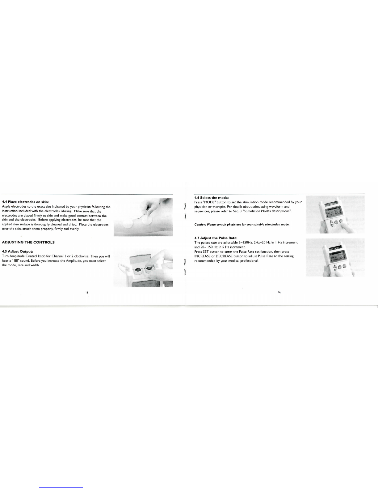
4.4
Placeelectrodes
on
skin:
Apply
electrodes
to the
exact
site
indicated
by
your
physician
following
the
instructionincluded
with
the
electrodeslabeling.Makesure that
the
electrodes
are
placed
firmly
to
skin
and
make
goodcontactbetween
the
skin
andthe
electrodes.Before
applying
electrodes,
be
sure
that
the
applied
skin
surface
is
thoroughly
cleaned
and
dried.
Place
the
electrodes
over
the
skin,
attach themproperly,
firmly
and
evenly.
ADJUSTING
THE
CONTROLS
4.5
Adjust
Output:
TurnAmplitude
Control
knob
for
Channel
I or2
clockwise.Then
you
will
hear
a
"
Bl!"
sound.Before
you
increase
the
Amplitude,
you
must
select
the
mode,
rate
and
width.
jp
4.6
Select
the
mode:
Press
"MODE"
button
tosetthe
stimulationmoderecommended
by
your
physician
or
therapist.
For
details
aboutstimulatingwaveform
and
sequences,
please
refer
to
Sec.
3
"StimulationModesdescriptions".
Caution:
Please consult
physicians
for
your
suitable
stimulation
mode.
4.7
Adjust
the
PulseRate:
The
pulses
rate
are
adjustable
2~l50Hz.
2Hz~20
Hz
inI Hz
increment
and
20~
ISO
Hzin5 Hz
increment.
Press
SET
button
to
enter
the
Pulse
Rate
set
function,then
press
INCREASE
or
DECREASE
button
to
adjust
Pulse
Rate
tothe
setting
recommended
by
your
medical
professional.
*

4.8
Adjust
the
Pulse
Width:
The
pulse
width
is
adjustable
50~300us
in
lOus
increment.
Press
SET
button
to
enter
the
Pulse
Width
set
function,
then
pressINCREASE
or
DECREASE
button
to
adjustPulse
Width
tothe
setting
recommended
by
your
medicalprofessional.
4.9
Adjust
Timer:
The
timer
is
adjustable
5~90minutes
or
continuous
in5
minutes
increment.
Continuous
option
is
just
the
next
step
to90
minutes,
i.e.
from
5-90
minutes
to
continuous
and
then
to5
minutes
isa
cycle.
During
5
minutes'
final
count
down,
the
clock
symbol
will
flashonce
every
one
second.
0
4.10
Adjust
Channel
Amplitude:
Turn
Channel
I or2
clockwise.
The
output
indication
will
be
showed
onthe
left
side
(Channel
I)
and
right
side
(Channel
2)oftheLCD
screen
as
long
asthe
unit
isin
operation.
Slowly
turn
the
Channel
Amplitude
control
until
you
reach
the
setting
recommended
by
your
medical
professional.Repeat
forthe
other
channel,
if
both
channels
are
tobe
used.
Caution:
Ifthe
stimulation
levels
ore
uncomfortable
or
become uncomfortable, reduce
the
stimulation
intensity
toa
comfortable
level
and
contact your physic/on
if
problems persist.
Operation Procedure Chart:
Press
"MODE"button
Burst
Mode
^'
Press
"MODE"button
Normal
Mode
Press
"MODE"button
MRVVMode
1
'
Press
"MODE"button
SO
Mode
1f
Press
"MODE"button
Bi-Pu/se
Mode
Adjust
(I)
Pulse
Width
(2)
Timer
by
"SET"
&
"
INCREASE/DECREASE"
button.
Adjust
(I)
Pulse
Rate
(2)
Pulse
Width
(3)
Timer
by
"SET"
&
"
INCREASE/DECREASE"
button.
Adjust
(I)
PulseRate
(2)
Pulse
Width
(3)
Timer
by
"SET"
&
"
INCREASE/DECREASE"
button.
Adjust
(I)
Pulse
Rate
(2)
Pulse
Width
(3)
Timer
by
"SET"
&
"
INCREASE/DECREASE"
button.
Adjust
(I)
Pulse
Width
(2)
Timer
by
"SET"
&
"
INCREASE/DECREASE"
button.

4.1
I
Turn
Unit
Off:
Turn
both
channel
controls
to
"off".
Thenunplug
the
electrode
lead
wires, graspingthem
bythe
plug,
notthe
cord.
If
treatment
will
be
resumedshortly
the
electrodes
maybe
left
onthe
skin.
When
the
electrodes
are
removed,
clean
the
skin
andthe
electrodesthoroughly
with
mild
soap
and
water.
If
there
is
skin
irritation
from
tape
or
gel,consult
yourprescriber.
Caution:
When
the
therapy
time
is
completed,
ifthe
user doesn't turn
offthe
amplitude
knob,
the
unit
will have
"Bi-Bi"
sound every
10
seconds until
the
amplitude
knob
is
turn
off
completely.
4.12
Patient
Compliance
Timer:
The
patient
compliance
timer
can
memorize
60
sets
of
operationrecords;
the
totalrecordtime
is999
hours.
After
the
unit
is
turnedoff,
youcan
start
touse
patientcompliancetimer.First,
press
and
hold"Mode"
button
and
turn
onthe
either
one
amplitude knob
simultaneously
to
initiatepatientcompliancetimer.
Individual
treatment
time:
Press
"INCREASE"
button
(triangle
button)
or
"DECREASE"
button
(inverted
triangle
button)
tosee
nextrecord
of
treatmenttime
with
the
number
of
times
or
previous
record
of
treatmenttime
with
the
number
of
times.
Press
and
hold"Set"
button
for3
seconds
to
delete
theon
showingrecord.
After
theon
showingrecord
is
deleted,
the
unitwill
sound
"Bi".
n
JU"
M
VI
un
iu
NOTE:
1.
Ifthe
treatment
time
is
under
one
minute,
it
will
notbe
recorded
For
example,
If
your
treatment
time
is
10
minutes
and30
seconds,
the
patient
compliance
timer
will
record
10
minutes,
not
11
minutes.
2. The
patient
compliance
timer
can
only
record
up to 999
minutes
for
each
treatment. Therefore,
if
you
keep
using
the
stimulator
for
over
999
minutes,
it
will
only
record
999
minutes
andthe
record
time
will
flash
to
mean
the
treatment time
is
over
999
minutes.

Cumulativetreatmenttime:
When
initiating
patient
compliance
timer,
press
"Mode"
to
shift
the
record
of
individual
treatmenttime
with
the
number
of
times
tothe
record
of
cumulative
treatmenttime.Whenshowing
the
record
of
cumulative
treatmenttime,there
will
bean
"M"
mark
flashing
onthe
upper
right
corner
of
middle-right
screen.
Press
and
hold"Mode"
&
"Set"button
simultaneously
for3
seconds
to
delete
all
the
records
including
individualtreatmenttimerecord
and
cumulativetreatment
timerecord.
%
The
patient
compliance timer will keep
the
records
even when
the
battery
has no
charge. Only when
users
press
and
hold
"
Set"
or
"Mode"
&
"Set",
the
recordswill
be
deleted.
H2
ICU
CARE
AND
MAINTENANCE
4.13
Portability:
Your
Unit
is
portable
andmaybe
clipped
toa
belt,shirtpocket,
braor
otherclothing.
4.14
"Low
Battery"
indicator:
When
thelow
powerindicator
flashes,
it
means
that
the
batteryshould
be
replaced
with
a newoneas
soon
as
possible.
However,
the
stimulatorwill
continue
to
operate
for
several
more
hours.

5.
HANDLING
AND
STORAGE
4.1
5
Battery:
^
To
replace
the
battery,
remove
the
battery
cover
and
extract
the
battery.
Replace
ita
with
a 9 V
alkaline
or
similar
rechargeable
battery.
Notice
that
the
battery
is*
inserted
correctly.
'i^l
nk.
4.16
Care
of
Electrodes:
To
avoid
skin
irritation
and
ensure
good
contact
with
skin,
clean
silicone
rubber
electrodes
with
soap
and
water
frequently.
The
electrodes
must
be
dried
completely
before
using.
^
Ifyouare
using
self-adhesive
electrodes,
please
disregard
this
procedure.
%*.
The
user
shall
always
usethe
electrodes which
fulfill
the
local regulatory
requirements.
4.17
Care
of
Electrode
cords:
Clean
the
electrodecords
by
wipingthem
with
damp
cloth.
Coatingthemlightly
with
talcum
powder
will
reduce
tangles
and
prolong
the
life.
.-*
in
Keep
.this
device
into
the
handy
carrying
case
and
storage
at
room
temperature.
6.
SPECIFICATION
Channel
PowerSource:
Output
waveform;
Pulse
Width:
Pulse
Frequency:
Adjustable
Intensity
Levels:
Five
Massage
Modes:
PatientComplianceTimer
Operationambient:
Storage
&
transportation:
Timer:
Lead
wires:
Safety
standard
Dual,isolatedbetween
channels
9V
DC
square
shape
battery(alkalinebatteries
or
similar rechargeablecell)
Asymmetric
biphasicsquarepulse.
Variable,
50~300us
Variable,
2-150
Hz
0to40
Volcs(at
load=500
ohm)
Burst
Normal
MRW
SD
Bi-Pulse
Memorize
60
sets
of
operationrecords
Total
recordtime
is999
hours
temperaturerange:IO-35°C
humidityrange:
20-90%RH
temperature
Range:
0°C-70°C
humidity
Range:
20-90%RH
5~90Minutes
auto-shutoff
or
Continuous
male
connector
2.00+OJ
IEC
6060
1
-
1
,
IEC6060
1
-
1
-2(EMC
test),
IEC
6060
1
-2-
1
0(partly
applied)

8.
TROUBLESHOOTING
Stimulation
Modes descriptions
Mode
Pulse
Frequency
Pulse
Width
Cycle
Time
BURST
Fixed
lOOHz
50~300us
0.5
Sec.
NORMAL
2~
1
SOHz,
50~300us
Constant.
MRW
2-1
SOHz
50~300us
1
Sec.
SD
2~l50Hz
50~300us
6
Sec.
BI-PULSE
Channel
1
fixat
4Hz,Channel
2 fixat
1
OOHz
50~300us
2
Sec.
Unit:
Voltage
At
Load
SOOQ
*The
values
of
digital
settings
hove
±5%
tolerance.
7
ACCESSORIES
4
PCS.
1
PC.
2
PCS.
IPC.
If
yourunit
does
not
seem
tobe
operatingcorrectly,refer
tothe
chartbelow
to
determinewhat
maybe
wrong.
Should
none
of
these
measures
correct
the
problem,
the
unit
should
be
serviced.
Self-Adhesive
Electrodes
9
V
Battery
Lead
Wires
Instructional
Manual
•TheLCD
indicatorlights
upbut
unit
does
not
functionproperly.
1.
Check
all
control
settings.
Are
they
setto
values
prescribed
by
your
medical
professional
?
2.
Are
electrodes
in
proper
position?
3.
Check
lead
wires.
Be
sure
all
connectors
are
firmly
sealed.
4.
Replace
cord
set
withanother
to
check
for
broken
wires.
1
Low
Batteryindicator
flash.
.
Replace
battery
with
a new
one.
'
None
ofLCD
indicatorslights
up.
I.
Replace
battery
with
a new
one.

Table of contents
Other EMSI Fitness Equipment manuals


