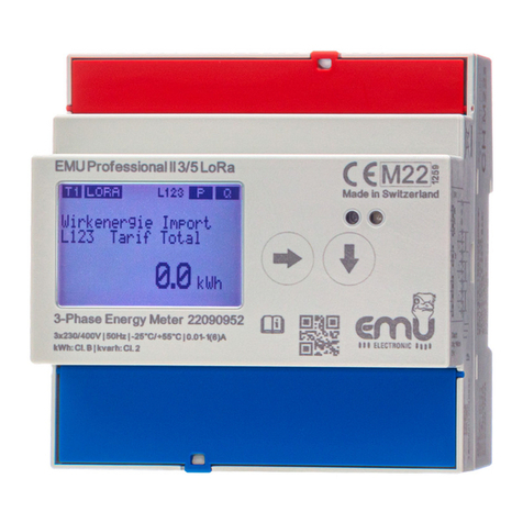
EMU ALLROUNDER User manual

• •
MANUAL
EMU ALLROUNDER
EMU PROFESSIONAL

34
EN
EMU PRODUCTS – ALL FROM ONE SOURCE
EMU provides everything from the energy meter
to a complete energy-monitoring system.
Data logger
M-Bus data Logger
•Integrated web server
•Access via web browser
•Plug and Play
•Designed for gas, water,
head, and electricity
•M-Bus to BACnet IP
•M-Bus to OPC UA
Web-based energy monitoring
Suitable to the data logger EMU Electronic offers a
Web-based energy monitoring solution.

35
Your benefits:
•Various locations monitored centrally
•Web-based software
•User-friendly operation
•Worldwide access
MENU NAVIGATION
Blue key Go to next unit
Active energy, active power etc.
Red
key
More information of unit E.g. phase L1, L2,
L3, total, Min. / Max values
Yellow
key
Service key, on the right side bellow the red
terminal cover. To save a configuration, push
the service key for 5 seconds.

36
EN
VIDEO ANIMATION
You can find a video about the configuration and
menu navigation on www.emuag.ch.
COMMISSIONING / CHECK-UP
To check for operation:
•Phase rotation
•Current per phase
Negative energy direction
•Sequence of phase (L1 L2 L3)
•Current Transformer ratio
•Terminal tightening torque
•Read-out interface: Correct address

37
TECHNICAL DATA
Nominal voltage Un3x230/400V (+/- 20%)
Accuracy class B (1%)
Nominal frequency fn50Hz, 60 Hz on request
Operating temperature -25° C...+55° C
Storage temperature -30° C...+70° C
Protection class Clamps: IP20
Case: IP51
Environmental class Mechanical: M1
Electro-magnetic: E1
Safety class 2
Description 3-phase static
Energy and Power Meter
EC-type examination CH-MI003-13022
Maximal air humidity
Annual average 75%,
Short-term 95%,
Non-condensing

38
EN
Direct connection
Current (Ist, Imin, Itr, Iref, Imax)
0.02 A / 0.25 A / 0.5 A / 5 A / 75 A (5(75))
Current transformer /5 und /1A
Current /5A (Ist, Imin, Itr, Iref, Imax)
0.01 A / 0.05 A / 0.25 A / 5 A / 6 A (5(6))
Current /1A (Ist, Imin, Itr, Iref, Imax)
0.002 A / 0.01 A / 0.05 A / 1 A / 1.2 A (1(1.2))
Installation instruction
Torque Connection
Flexible wire
Direct
max. 35mm2
strand
Current transformer
max. 6mm2strand
Input lead L1/L2/L3 2-3 Nm 1.3 - 1.6 Nm
Neutral conductor 2-3 Nm 1.3 - 1.6 Nm
S0 pulse output 0,4 Nm (max 2.5mm2strand)
Tariff control 0,4 Nm (max. 2.5mm2strand)

39
Cable requirement >65A
Type: Wire (Cu)
Cross-section: 35mm²
Outside-Ø: 9,55 mm
Example: E-Number 105502800, available from Swiss
electrical wholesale
DISPLAY LANGUAGE
Display language can be selected between English and
German (Deutsch).
Congure of display language
1. Blue key to Adjustments
2. Red key to Language (Sprache)
3. Push Service-Key briefly
4. Adjust Language by blue key
5. Saving: Push Service key for 5 seconds,
until digits are not blinking

40
EN
TARIFF CONTROL
Tariff changeover takes place by 230V to corresponding
terminal.
Tarif 2 = 230V on terminal E4 and E5 (N)
Double-tariff Four-tariff
E4 E4 E3
T1 0 T1 0 0
T2 1 T2 1 0
T3 0 0
T4 1 0
0 = No voltage
1 = Voltage

41
CURRENT TRANSFORMER RATIO
Current transformer ratio can be adjusted from 5/5 to
20‘000/5A and 1/1 to 4’000/1A
Left (blue) key = Change of digit / number
Right (red) key = Go to next digit / number
Current transformer /5A
AABCC : 5A
AA adjustable in steps of 1
B adjustable in steps of 1
CC adjustable in steps of 5
Current transformer /1A
YYYY : 1A
Y adjustable in steps of 1

42
EN
Conguration of current transformer ratio
1. Blue key to Transformer ratio
2. Push service key briefly
3. Adjust secondary current by blue key
4. Go to primary current by red key
5. Adjust first two digits by blue key
6. Go to next digit by red key
7. Adjust digit by blue key
8. Go to next digit by red key.
9. Adjust next two digits by blue key.
10. Saving: Push Service key for 5 seconds,
until digits are not blinking

43
S0 PULSE-OUTPUT
The four S0 pulse-outputs are designed according to
EN62053-31 (DIN 83864).
Pulse rate and pulse lengths can be configured by the keys.
Default settings ex-factory
1. S0 Output = Active Energy Import (12+13)
2. S0 Output = Reactive Energy Import (10 + 11)
3. S0 Output = Active Energy Export (8 + 9)
4. S0 Output = Reactive Energy Export (6 + 7)
Current transformer meter 10 Impulse / kWh
Direct meter 1000 Impulse / kWh
EMU Allrounder
The EMU Allrounder only has one pulse-output for active
energy import.

44
EN
Conguration of pulse rate
1. Blue key to Adjustments
2. Red key to S0 Pulse Rate
3. Push service key briefly
4. Move decimal place by blue key
5. Example 1000.000 = 1000 Impulse
6. Saving: Push Service key for 5 seconds,
until digits are not blinking
Conguration of pulse length
1. Blue key to Adjustments
2. Red key to S0 Pulse Duration
3. Push service key briefly
4. Adjust pulse length by blue key
5. Saving: Push Service key for 5 seconds,
until digits are not blinking

45
S0 pulse-output
Opto Power MOSFEET
5 – 230 VAC or VDC, max. 90mA
Rate per kWh / kvarh
0.001, 0.01, 0.1, 1, 10, 100, 1000, 10‘000
Length
Adjustable from 4 to 250 milliseconds in steps of 2 ms

46
EN
M-BUS ADDRESS / CONFIGURATION
Recommended cable
Twisted pair, shielded, cross-section depending on cable
length. Type: JY(St)Y 2x0.8 to 1.5 mm2
Default settings ex-factory
Secondary address = Serial number
Primary address = 0
Baud rate = 2400
Conguration via M-Bus
Primary and secondary address, baud rate and read-out data
can be configured by the free EMU MB-Connect software or
by the keys. The M-Bus interface is designed according to
EN 13757-2,-3 (formerly EN1434-3).

47
Conguration of primary / secondary address
1. Blue key to Adjustments
2. Red key to MBUS Primary address (or Sec.)
3. Push service key briefly
4. Adjust first digit by blue key
5. Go to next digit by red key
6. Saving: Push Service key for 5 seconds,
until digit is not blinking.
Conguration of baud rate
1. Blue key to Adjustments
2. Red key to MBUS Baud rate
3. Push service key briefly
4. Adjust baud rate by blue key
5. Saving: Push Service key for 5 seconds,
until digits are not blinking

48
EN
TCP/IP INTERFACE
Default settings ex-factory
IP-Adresse = 192.168.1.100
Subnet = 255.255.255.0
Gateway = 0.0.0.0
Conguration of IP address
1. Blue key to Adjustments
2. Red key to IP Address
3. Push service key briefly
4. Adjust first digit by blue key
5. Go to next digit by red key
6. Saving: Push Service key for 5 seconds,
until digits are not blinking

49
Conguration of Subnet
1. Blue key to Adjustments
2. Red key to Subnet
3. Push service key briefly
4. Adjust first digit by blue key
5. Go to next digit by red key
6. Saving: Push Service key for 5 seconds,
until digits are not blinking
Update interval
Values on the TCP/IP module are updated in the following
interval:
Current per phase and total: 1 second
Active power per phase / total: 1 second
Reactive power per phase / total: 1 second
Apparent power per phase / total: 1 second
All other values: 10 seconds

50
EN
Factory reset
By factory reset (menu point Adjustments) the TCP / IP
module is set to the default settings.
TCP/IP interface connected directly to computer
For a successful connection between an EMU Professional
TCP / IP (not connected to network) and a computer, please
consider the following points:
Counter and computer must be in the same subnet.
E.g. Subnet mask: 255.255.255.0
Network cable type: Cross
Computer requires a fixed IP address
Please contact your local / internal IT support for any ques-
tions regarding the TCP/IP connection.

51
RELAY OUTPUT
The S0 pulse-outputs can be configured as a relay-output
and can be switched via TCP/IP module or special M-Bus
protocol.
Conguration of relay-output
1. Blue key to Adjustments
2. Red key to Assignment output X
3. Push service key briefly
4. Adjust to Relay Output by blue key
5. Saving: Push Service key for 5 seconds,
until digits are not blinking

52
EN
PEAK-CONTROL / THRESHOLD
Threshold
The following values can be chooses as a threshold:
Active Power, Reactive power, Apparent power
Current total Current per phase L1 / L2 / L3
Default settings ex-factory
Threshold: 5.000 kW
Status: Not active
Response time / release time
The response and release time is adjustable between 0 and
9999 seconds.
Response time: Time, until contact switches
Release time: Time, until contact switches after th-
reshold is not exceeded anymore.
The threshold function can be assigned to any output S0.
Other manuals for ALLROUNDER
1
This manual suits for next models
5
Table of contents
Other EMU Measuring Instrument manuals