Jinko JK9306 User manual

OPERATION MANUAL
JK9306
Digital Power Meter
Changzhou Jinailian Electronic Technology Co., Ltd
No.C3,Building 22,New Impetus Pioneering Center, No.1,Qingyang North
Road,Tianning District,Changzhou,Jiangsu,CN
TEL: 0086-519-85563477 FAX: 0086-519-85565067
https://jinailian.en.alibaba.com www.jk17.com www.jaldz.com

Contents
Chapter 1 Overview ..................................................................................................................1
1.1 Introduction to the instrument...................................................................................................1
1.2 Unpacking Inspection..................................................................................................................2
1.3 Conditions of use........................................................................................................................2
1.3.1 Power connection....................................................................................................................2
1.3.2 Fuses........................................................................................................................................2
1.3.3 Environment.............................................................................................................................2
1.3.4 Preheating................................................................................................................................3
1.4 Instrumentation and other features...........................................................................................3
Chapter 2 Front and Rear Panel Instructions and Getting Started...............................................3
2.1 Front panel description...............................................................................................................3
2.2 Description of the rear panel......................................................................................................4
Chapter 3 Basic Operation Instructions......................................................................................4
3.1 Startup........................................................................................................................................4
3.2 Definition of display area............................................................................................................4
3.3 Switching of the display interface...............................................................................................5
3.3.1 DISP button..............................................................................................................................5
3.3.2 SETUP button...........................................................................................................................6
Chapter 4 Basic Page Display and Parameter Setting..................................................................6
4.1 <Measurement display> interface..............................................................................................6
4.1.1 Test mode................................................................................................................................7
4.1.2 Test range.................................................................................................................................7
4.1.3 Measurement parameters.......................................................................................................8
4.1.4 Comparison Explanation..........................................................................................................8
Chapter 5 System Settings.........................................................................................................8
5.1 Baud rate setting.........................................................................................................................8
5.2 Calibration mode setting.............................................................................................................9
5.3 Address Setting...........................................................................................................................9
5.4 Filter settings.............................................................................................................................10
5.5 Interface mode..........................................................................................................................10
5.6 Zero reset setting......................................................................................................................11
5.7 Language Setting.......................................................................................................................11
5.8 Measurement source settings...................................................................................................12
5.9 Flash mode setting....................................................................................................................12
5.10 Shortcut Settings.....................................................................................................................13
5.11 Key sound settings..................................................................................................................13
5.12 Power Cap...............................................................................................................................14
5.13 Upper current limit.................................................................................................................14
5.14 Alarm sound setting................................................................................................................15

Chapter 6 Correct Measurements.....................................................................................15
6.1 Wiring method..................................................................................................................15
6.1.1 Current terminal internal connection............................................................................16
6.1.2 External current terminal...............................................................................................16
Chapter 7 Basic Principles and Technical Specifications............................................ ........17
7.1 Basic principles..................................................................................................................17
7.1.1 Measurement parameters and symbols........................................................................18
7.1.2 Calculation formula........................................................................................................18
7.1.3 Hardware range..............................................................................................................20
7.2 Instrument parameters.....................................................................................................20
Chapter 8 Jinko Power Meter Module Communication Instructions V1.0..........................21
Chapter 9 Package and Warranty......................................................................................24
9.1 Complete Set.....................................................................................................................24
9.2 Marks................................................................................................................................24
9.3 Packaging..........................................................................................................................24
9.4 Transport...........................................................................................................................24
9.5 Storage..............................................................................................................................24
9.6 Warranty............................................................................................................................24

1
Chapter 1 Overview
Thank you for purchasing and using our products. Before you use this instrument, please confirm
it according to the "Setting and Warranty" section at the end of the manual. If there is any
discrepancy, please contact our company as soon as possible to protect your rights.
1.1 Instrument Introduction
JK9306 series single-phase digital power analyzer (digital power meter) uses a high-speed
32-bit processor and a professional DSP digital signal processor. It has fast speed, frequency
bandwidth, full-featured, compact structure, stable testing, simple operation and good
performance. The human-machine interface is a new generation of digital power analyzer. The
main parameters that can be measured are: RMS value of voltage and current, AC component of
voltage and current, DC component of voltage and current, active power, reactive power,
apparent power, electrical energy timing, power factor, frequency, peak factor of voltage and
current, peak value of voltage and current etc. electric parameters, depending on the model of
the instrument, some instruments do not have a harmonic analysis function.
This manual covers the JK9306 single-phase power analyzer. It covers most of the power
supplies on the market with the advantages of a large input bandwidth (45 ~ 400Hz). In addition
to the basic electrical parameter measurement, the four instruments also provide intuitive
comparison functions. Input waveform display, meanwhile, the HANDLER interface, RS232C /
RS485 interface and USBTMC, USBCDC interface provided by the instrument provide conditions
for the instrument to be used in automatic sorting system and computer remote operation; the
difference between different models is mainly the current measurement range and Whether it
has the function of harmonic analysis, the maximum test current is 40A, and the measurement
accuracy is stable. The specific differences can be found in the following instrument model
comparison table.
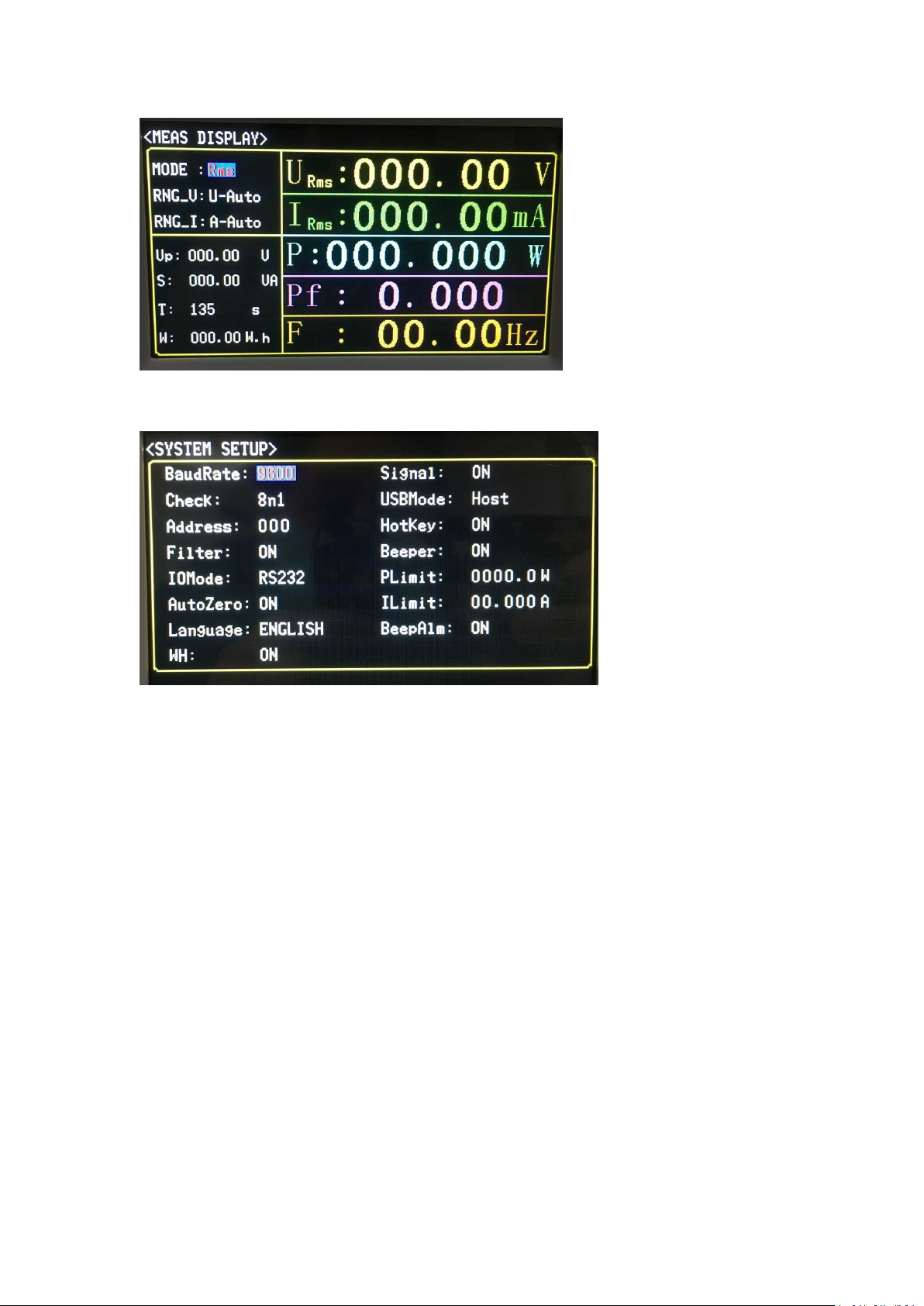
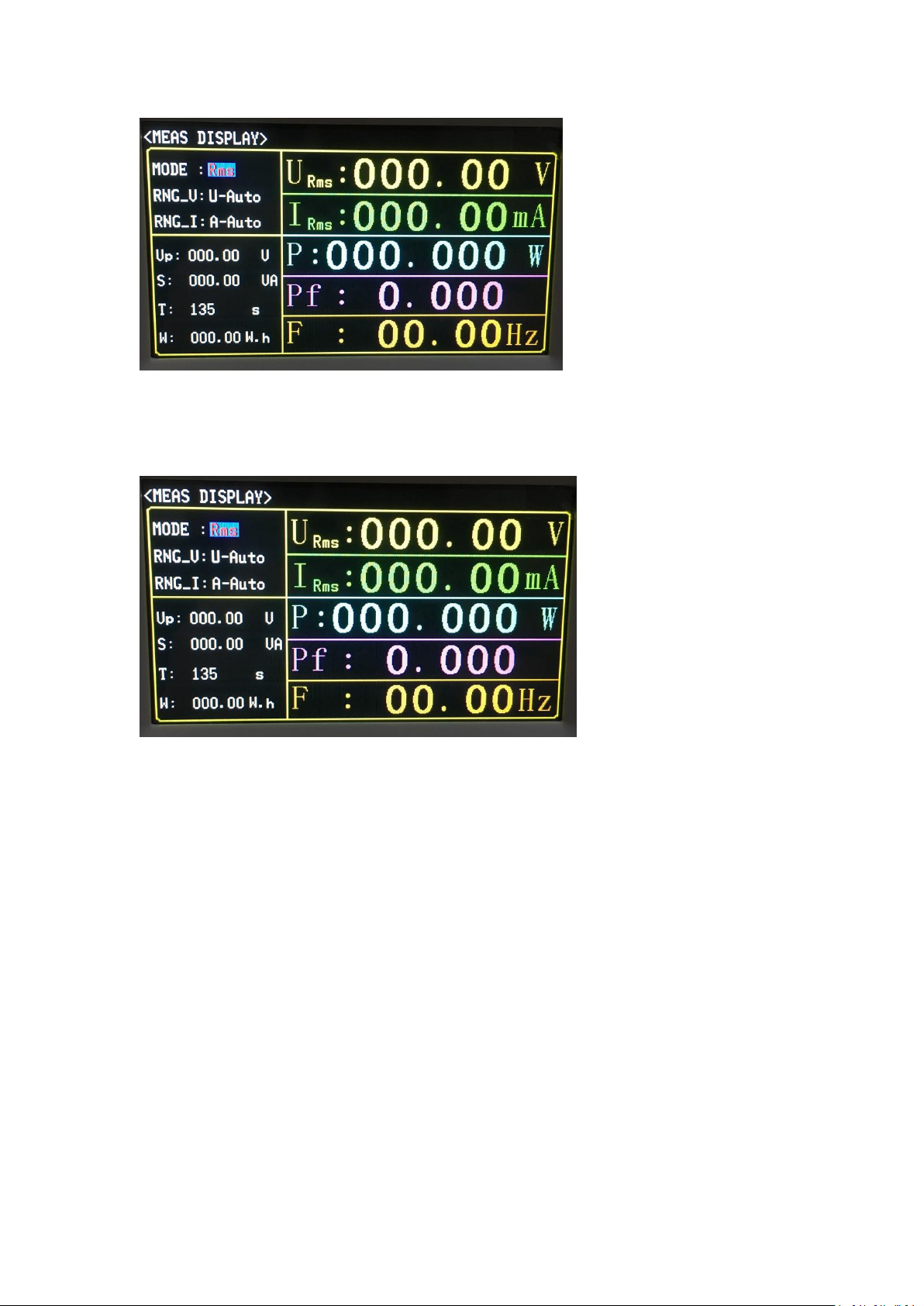
The main features of the instrument:
4.3 inch LCD liquid crystal display;
Soft power switch;
Chinese and English optional operation interface;
Input frequency range (45 ~ 400Hz);
The range can be controlled automatically / manually;
The maximum test current is 40A (depending on the model), and the minimum current
can be 1uA (depending on the model);
Controllable synchronization trigger source;
Provide 5kHz line filter switch;
Flexible energy integration control;
Parameter comparison and Handle controllable output function;
Parameter file selection function;
Harmonic analysis function (related to specific models);
Waveform display function;
Support U disk file storage, instrument programs can be upgraded through U disk;
Serial interface: RS-232C provides great convenience for serial communication between the
instrument and peripherals. Peripherals can set various functions and parameters of the

2
instrument through this interface, which can basically replace the functions of the panel
keyboard.
1.2 Unpacking inspection
After opening the box, you should first check whether the instrument is damaged due to
transportation. We do not recommend that you power on the instrument when the appearance
is damaged.
The front panel of the instrument is marked with the specific model of the instrument and the
main measurement range. Check that it is the same as the model you ordered, and confirm it
according to the packing list. If there is any discrepancy, please contact our company or the
distributor as soon as possible to protect your rights. .
The comparison between the instrument model and basic functions is shown in Table 1-1:
Note: It is best to keep the packing box of the instrument properly after unpacking, so as to avoid
unnecessary damage to the instrument due to the unmatched packing box during later
transportation.
1.3 Conditions of use
1.3.1 Power connection
Power supply voltage: 200 to 240 VAC
Power frequency: 47 to 63 Hz
Power supply range: no less than 30 VA.
The power input phase line L, neutral line N, and ground line E should be the same as the power
plug of the instrument.
This instrument has been carefully designed to reduce the clutter interference caused by the AC
power input. However, it should still be used in a low noise environment as much as possible. If it
cannot be avoided, please install a power filter.
Warning: In order to prevent leakage to the instrument or people, the user must ensure that the
ground wire of the power supply is reliably connected to the ground.
1.3.2 Fuses
The instrument is equipped with a fuse at the factory. Users should use the fuse provided by our
company.
Model difference and function description
JK9306 conventional type, 600V / 2A, without harmonic analysis function
1.3.3 Environment
Normal working temperature: 0 ℃ ~ 40 ℃, humidity: 20 ~80% RH
Reference working temperature: 20 ℃ ± 8℃, humidity: <80% RH
Transportation environment temperature: 0 ℃ ~ 55 ℃, humidity: 93% RH
Please do not use it in dust, vibration, direct sunlight or corrosive gas.
In order to ensure good ventilation of this test instrument, do not block the left ventilation hole
to maintain the accuracy of the instrument.
This instrument has been carefully designed to reduce the clutter interference caused by the AC
power input. However, it should still be used in a low noise environment as much as possible. If it
cannot be avoided, please install a power filter.
If the instrument is not used for a long time, please store it in the original box or similar box in a

3
ventilated room with a temperature of 5 ℃~40 ℃and a relative humidity of not more than
85% RH. The air should not contain harmful impurities that corrode the measuring instrument.
Avoid direct sunlight.
1.3.4 warm up
In order to ensure the accurate measurement of the instrument, the warm-up time should be no
less than 30 minutes.
Do not turn the instrument on and off frequently as this may cause internal data confusion.
1.4 Instrument and other features
Power consumption: The power consumption is about 16 VA.
Shelf size (W * H * D): 215 * 88 * 335.
Overall dimensions (W * H * D): 235mm * 105mm * 360mm; this size includes the size of the
jacket.
Weight: about 3.85kg;
Chapter 2 Front and Rear Panel Instructions and Getting Started
This chapter describes the basic operation steps of JK9306 series instruments. Before using
JK9306 series instruments, please read this chapter in detail so that you can quickly familiarize
yourself with the operation of JK9306 series instruments.
2.1 Front panel description
Figure 2-1 briefly describes the front panel of the JK9306 series.
1
USB HOST
The USB HOST interface is used for USB flash disk storage and
upgrade.
2
Trademarks and models
Instrument trademarks and models
3
LCD liquid crystal display
480 ×272 dot matrix liquid crystal display for
human-computer interactive display
4
LCD liquid crystal display
To be used to enter the “Measurement Display”page
5
Universal direction key
(CURSOR)
Up, down, left and right direction keys and confirm key.
6
Setup function key SETUP
To be used to enter the “System Setup”page.
7
Comparison PASS / FAIL
display
In the file or comparison display interface, the comparison
result will be displayed by PASS / FAIL (green / red).
8
ENTER
After moving the cursor position, the soft key area corresponds
to different functions. Press to modify the corresponding

4
parameter value.
9
Power switch (POWER)
Power switch. The key is green when the instrument is turned
on, and the key is red when the instrument is turned off.
Table 2-1 Front panel description
2.2 Rear panel description
Figure 2-2 briefly describes the rear panel of the JK9306 series.
1
Power socket
For inputting AC power.
2
RS232C interface
Realize serial communication with computer.
3
Label
Used to indicate the specific S / N number of the instrument.
4
Current measurement input negative terminal (I-) (I- load negative terminal)
5
Positive terminal of current measurement input terminal (I +) (positive terminal of I +
load)
6
Positive terminal of voltage measurement input terminal (V +)
7
Negative terminal (V-) of voltage measurement input terminal
Table 2-2 Rear panel description
Chapter 3 Basic Operation Instructions
The basic operation description of JK9306 series keys:
1) Use the menu buttons (DISP, SETUP) and soft keys to select the page you want to display.
2) Use the arrow keys (←,↑,→,↓) to move the cursor to the settable parameter area, and
the corresponding area will change to the cursor color (blue).
3) The soft key functions corresponding to the parameters in the current cursor area will be
displayed in the "soft key area". Use the common soft keys under the LCD to perform
corresponding operations or press ENTER to quickly modify the enumeration status of the
selected parameter.
3.1 boot
Plug in the three-wire power plug to ensure a reliable connection to the power ground. Press the
power switch in the lower left corner of the front panel of the instrument to turn it on and
display the startup screen.
Figure 3-1 shows the startup screen of JK9306. The startup screen includes some product

5
information such as the trademark, instrument model, version number of Tonghui Company.
3.2 Display area definition
The JK9306 series uses a 24-bit color 4.3-inch color LCD screen with a resolution of 480 ×272.
The content displayed on the screen is divided into the following display areas. Take the
<Measurement Display A> page as an example.
3-2. The meaning of each area is shown in Table 3-1.
(Figure 3-1 JK9306 startup screen)
1 Main menu area This area indicates the name of the current page.
2 Test condition area This area is used to display and quickly modify the common
conditions of the test.
3 Message prompt area This area is used to display various prompt information
during testing and setup.
4 Icon prompt area This area is used to display the U disk, keyboard lock and test
speed icon indication.
5 Measurement result display area This area displays the test parameter results. The
current page is divided into 4 windows to set different measurement parameters.
Table 3-1 Meaning of each area
Remarks: Due to the different layouts of different pages, the display information (2,
3, 5) of different pages may not be the same as the area division location. It is for
reference only, and you can see the details of each display page.
3.3 Display interface switching
The DISP key and the SETUP key are the two keys most frequently used in the page
switching process, which are the entrances to test-related pages and setup-related
pages, respectively.
3.3.1 Measurement display button DISP
Press the DISP key to enter the measurement display home page

6
3.3.2 Measurement setup button SETUP
Press the SETUP key to enter the system setting page.
Chapter 4 Basic Page Display and Parameter Setting
The general setting method of JK9306 series instruments is as follows:
1) Use the arrow keys to move the cursor to the position of the parameter to be modified;
2) For enumerated parameters, according to the function prompts of the LCD soft keys,
press the corresponding soft key to complete the modification of the parameter value or press
ENTER to cyclically modify the enumerated parameter value;
3) For numerical parameter values,
a. According to the function prompts of the soft keys, press the corresponding soft key to
achieve fine adjustment (increase or decrease) of the value;
4.1 <Measurement display> interface
Press the DISP key, and the <Measurement Display> page will be displayed on the screen.

7
(Figure 4-1 Measurement display interface)
4.1.1 Test mode
The measurement mode of JK9306 is: True RMS measurement mode (RMS).
(Figure 4-3 Measurement display interface setting measurement mode)
Note: As shown in Figure 4-3 below, after the cursor is moved to the corresponding parameter,
the corresponding function changes and selection operations of the soft key zone parameters are
only described in detail on this page. The other pages are basically the same as this operation, so
For the modification of other page parameter values, please refer to the screenshot description
here.
Setting operation steps:
4.1.2 Test range
JK9306 has 4 voltage test ranges: 75V, 150V, 300V, 600V, U-Auto;
JK9306 has 7 current test ranges: 1mA, 3mA, 10mA, 40mA, 150mA, 500mA, 2A, I-Auto.
Factory default settings:
The voltage is in the automatic voltage range (U-Auto);
The current is in the automatic current range (I-Auto).
Setting operation steps:
1) Move the cursor to the range V / I area, the following soft keys will be displayed in the soft key
area of the screen

8
■Auto / AUTO: Used to set the range to automatic mode.
■↓(-): Used to select the small range down.
■↑(+): Used to select a large number of ranges up.
2) Press the corresponding soft key or press ENTER to complete the corresponding setting.
4.1.3 Measurement parameters
Measurement parameter settings under the measurement display page (display 5 measurement
parameters),
Factory default settings: voltage (U), current (I), power (P), power factor (PF), frequency (Hz)
Press once to switch once (switch between auto and power);
For instructions and suggestions on the use of the synchronization function, see the section on
the synchronization signal on the <Measurement Settings> page.
4.1.4 Comparison description
The instrument can set the upper limit of power and current. If it exceeds the set upper limit, the
instrument will issue an alarm.
Chapter 5 System Settings
Press SETUP to enter the system setting interface, as shown in the figure:
Parameter setting interface, you can set the baud rate, check mode, address, filter, interface
mode, etc.
5.1 Baud rate setting:
The instrument supports 8 baud rates: 1200, 2400, 4800, 9600, 19200, 38400, 57600, 115200.
Users can set according to their needs. The setting steps are as follows:
Use the cursor keys to move the cursor to the baud rate area, press [ENTER], then press the up
and down keys to select, ↑to increase the value, ↓to decrease the value. After selection,
press [ENTER] to complete the setting.
as the picture shows:

9
5.2 Calibration mode setting:
The instrument supports 4 kinds of calibration methods, which are 8n0, 8n1, 8e1, 8o1. Users can
set according to their needs. The setting steps are as follows:
Use the cursor keys to move the cursor to the calibration mode area, press the [ENTER] key, and
then press the up and down keys to select. After the selection is completed, press [ENTER] to
complete the setting.
5.3 Address setting:
The instrument address supports two types, 000,001, and users can set it according to their
needs. The setting steps are as follows:
Use the cursor keys to move the cursor to the address area, press the [ENTER] key, and then press
the up and down keys to select. After the selection is completed, press [ENTER] again to
complete the setting.

10
5.4 Filter settings
The instrument can set the filter on and off. Users can set it according to their needs. The setting
steps are as follows:
Use the cursor keys to move the cursor to the filter area, press [ENTER], then press the up and
down keys to select, “On”and “Off”. After the selection is completed, press [ENTER] to
complete the setting.
5.5 Interface Mode
The instrument supports 2 interfaces, namely USB and RS232. Users can set it according to their
needs. The setting steps are as follows:
Use the cursor keys to move the cursor to the interface mode area, press the [ENTER] key, and
then press the up and down keys to select. After the selection is completed, press [ENTER] to
complete the setting.

11
5.6 Zero-setting:
The instrument can be set to zero setting on and off. Users can set it according to their needs.
The setting steps are as follows:
Use the cursor keys to move the cursor to the zero return area, press the [ENTER] key, then press
the up and down keys to select, "On" and "Off". After the selection is completed, press [ENTER]
to complete the setting.
5.7 Language settings
The instrument supports 2 languages, Chinese and English. The setting steps are as follows:
Use the cursor keys to move the cursor to the language area, press the [ENTER] key, and then
press the up and down keys to select. After selecting, press the [ENTER] key to complete the
setting.

12
5.8 Measurement source settings
The instrument can set the measurement source settings on and off. Users can set according to
their needs. The setting steps are as follows:
Use the cursor keys to move the cursor to the measurement source area, press the [ENTER] key,
then press the up and down keys to select, "On" and "Off". After the selection is completed,
press [ENTER] to complete the setting.
5.9 Flash Mode Setting
The instrument supports 2 flash memory modes, host and device. Users can set according to
their needs. The setting steps are as follows:
Use the cursor keys to move the cursor to the flash mode area, press the [ENTER] key, and then
press the up and down keys to select. After selecting, press the [ENTER] key to complete the
setting.

13
5.10 Shortcut Settings
The instrument can be set with shortcut keys on and off. Users can set it according to their needs.
The setting steps are as follows:
Use the cursor keys to move the cursor to the shortcut key area, press the [ENTER] key, then
press the up and down keys to select, "On" and "Off". After the selection is completed, press
[ENTER] to complete the setting.
5.11 Button sound settings
The instrument can be set to switch on and off. Users can set according to their needs. The
setting steps are as follows:
Use the cursor keys to move the cursor to the key sound area, press the [ENTER] key, then press
the up and down keys to select, "On" and "Off". After the selection is completed, press [ENTER]
to complete the setting.

14
5.12 Power Cap
The instrument supports setting the upper power limit. The setting range is 0000.0 ~ 9999.9W.
The setting steps are as follows:
Use the cursor keys to move the cursor to the power upper limit area, press the [ENTER] key, and
then press the up and down keys to select. The ↑key increases the value, the ↓decreases
the value, ←moves the setting number to the left, →moves to the setting number of the
right.
After setting press [enter] again to complete the setting.
5.13 Current upper limit setting
The instrument supports setting the current upper limit, the setting range is 00.000 ~ 50.000A,
the setting steps are as follows:
Use the cursor keys to move the cursor to the current upper limit area, press [ENTER], and then
press the up and down keys to select. The ↑key increases the value, the ↓decreases the
value, ←moves the setting digits to the left, →moves to the right setting the digits. After
setting, press the [ENTER] key to complete the setting

15
5.14 Alarm sound setting
The instrument can set the alarm sound on and off. Users can set it according to their needs. The
setting steps are as follows:
Use the cursor keys to move the cursor to the alarm sound area, press the [ENTER] key, then
press the up and down keys to select, "On" and "Off". After the selection is completed, press
[ENTER] to complete the setting.
Chapter 6 Proper Measurement
6.1 Wiring method
JK9306 series instruments provide four test wiring input terminals, namely high voltage end, low
voltage end, high current end, and low current end.
Because the voltage and current are floating inputs, there can be multiple combinations of test
wiring methods, and different applications can be connected to the corresponding test circuit.
Here are two recommended wiring methods for the measurement circuit.
Tip: Considering that the presence of distributed capacitance may affect the test, in order to
reduce the impact of distributed capacitance on the test circuit, it is recommended to make the
current test terminal as close as possible to the ground of the input source, that is, the current
terminal is connected to the Low-end.

16
6.1.1 Current terminal internal connection
This method is suitable for low-power testing, that is, the test current is relatively small. It is
recommended to use it to make the current test more accurate, and the voltage measurement
will cause small errors due to the voltage drop caused by the current on the ammeter
(This error can be ignored). The wiring method and brief principle are shown in Figure 6-1:
(Figure 6-1 Ammeter connection method-suitable for small current connection method)
6.1.2 External current terminal
This method is suitable for high-power load testing, that is, the test current is relatively large. It is
recommended to make the voltage test more accurate, and the current measurement will cause
a small error due to the shunting of the voltmeter (this error can be ignored). The wiring method
and brief principle are shown in Figure 6-2:
(Figure 6-2 Ammeter external method-suitable for high current connection method)
Recommended process for connecting test lines:
1) Connect the positive and negative ends of the current in series with the load (connected into a
loop, the negative end of the current is connected to the neutral line);
2) Connect the positive and negative voltage ends to the load or the input source according to
the requirements (that is, the positive voltage end is connected to the live wire, and the negative
voltage end is connected to the current positive end or current negative end);
3) Confirm again that the live wire of the input source is connected to the positive terminal of the
voltage, and the neutral wire of the input source is connected to the negative terminal of the
current.

17
Chapter 7 Basic Principles and Technical Specifications
7.1 Basic principles
System principle and functional block diagram, as shown in Figure 7-1:
(Figure 7-1 System Structure)
The main structure of the JK9306 series single-phase power meter is to input the voltage and
current of the equipment under test through the instrument to the instrument through
differential input. Through the instrument's internal amplification, filtering, sampling, and AD
conversion, the analog signals of voltage and current are synchronized and sampled. It is
converted into digital quantities Ui and Ii, and then the CPU uses discrete integration to obtain
the voltage effective value, current effective value, active power, and power factor according to
the following formula and sends them to the liquid crystal display. Because the calculation of the
effective value includes the AC component And DC components, and the AC waveform may
become a non-standard waveform due to partial distortion, so the rms calculations here are true
rms values, that is, true rms values. The calculated power also includes the AC and DC
components of the voltage and current. Therefore, the power calculation belongs to the average
power and is also the real power value, that is, the active power. The sign of the power
represents the flow of power (respectively whether the power provided by the power supply to
the load or The energy provided by the load to the power supply). The power factor is the ratio of
the active power to the apparent power (total power). Theoretically, there is no sign of the power
factor. However, in the application of the power meter, the sign of the phase relationship
between voltage and current is determined by the sign of -1. Between ~ + 1, a positive value
represents the voltage leading current and a negative sign represents the voltage lagging current.
In addition to the RMS test mode, this series of instruments also provide AC and DC test modes.
If the input source includes AC and DC components, you can switch modes to view the
corresponding AC and DC components, respectively.
For harmonics, some instrument models do not have a harmonic analysis function, and
instruments with a harmonic analysis function are for power frequency power signals (50 / 60Hz),
and for harmonic results of non-power frequency signals, this series of instruments can View but
no precision indicator. This series of instruments provide optional opening of the 5kHz filter. This
filter is not suitable for non-power frequency power supply and needs to be manually turned off
(optional in the measurement settings). The harmonic order that can be analyzed and viewed is 2
~ 50 times.
Table of contents
Other Jinko Measuring Instrument manuals