EMUGE FRANKEN HE 2-IKZZ User manual

HE 2 - IKZZ
HE 2 - IKZ
HE 2 - MK
HE 3
HE 3 - MK
Quick-change adapters HE
Operating instruction

HE
2 Operating instruction edition: 01.02.2017
Contents:
1Application range, safety instructions and technical data...........4
1.1 Application range, determined use ....................................................................4
1.2 Safety instructions and hints..............................................................................5
1.3 Proprietary rights ...............................................................................................5
1.4 Dimensions and technical data..........................................................................6
1.4.1 Type HE, HE-IKZZ, HE-IKZ, for taps/cold-forming taps.......................... 6
1.4.2 Type HE-MK, for drill and countersink .................................................... 7
2Putting the quick-change adapters into operation........................8
2.1 Unpacking..........................................................................................................8
2.2 Insert tool...........................................................................................................8
2.2.1 Insert tap / cold-forming tap .................................................................... 8
2.2.2 Insert drill or countersink......................................................................... 9
2.3 Detach tool ......................................................................................................10
2.3.1 Detach tap / cold-forming tap................................................................ 10
2.3.2 Detach drill or countersink .................................................................... 10
3Maintenance...................................................................................11
3.1 Maintenance schedule.....................................................................................11
3.2 External cleaning.............................................................................................11
4Storage when not in use ...............................................................11

HE
Operating instruction edition: 01.02.2017 3
Warning signs, symbols
This operating instruction uses the following symbols:
Attention
Marks special instructions, rules and prohibitions which are important in order to avoid
any damage.
Please observe these instructions!
Instruction
Marks application instructions and other useful information.
Sectional view:
Quick-change adapter HE

HE
4 Operating instruction edition: 01.02.2017
1 Application range, safety instructions and technical data
1.1 Application range, determined use
Application of the adapters:
Adaptation of taps/cold-forming taps acc. to:
DIN or ISO or ASME dimensions
These adapters are designed to be used in all quick-change tap holders, EMUGE
types:
HF 20 HF20/HD/Spezial Softsynchro®6 HF 30
Production of right-hand and left-hand threads
Possible use in vertical and horizontal machining level
Locking and centering of the taps/cold-forming taps with quick-change adapters type
HE is executed via three screws. The torque arising during the thread producing
cycle is transferred via the square in the quick-change adapter.
In quick-change adapters type HE-MK, drill or countersink are adapted by form-fitting
via the inner taper of the quick-change adapters (acc. to DIN 228B).
Owing to the clamping principle, each shank diameter requires a separate quick-
change adapter.
Following adapter types are available:
Type HE:
For holders without internal coolant-lubricant supply, e.g. quick-change tap
holder HF.
Type HE/IKZZ:
For holders with internal coolant-lubricant supply e.g. quick-change tap holder
Softsynchro®6 and HF20/HD/Spezial and taps/cold-forming taps with coolant-
lubricant bore hole.
The maximum coolant-lubricant pressure is determined by the used quick-change
tap holder, but not more than 50 bar.
Type HE/IKZ:
For adapters with internal coolant-lubricant supply, e.g. quick-change tap holder
Softsynchro®6 and HF20/HD/Spezial and taps/cold-forming taps without coolant-
lubricant bore hole. The coolant-lubricant supply goes along the tool shank.
The maximum coolant-lubricant pressure is determined by the used quick-change
tap holder, but not more than 50 bar.
Type HE/MK:
Adaptation of drills and countersinks with taper shank according to DIN 228 B.
The non-determined use exempts the manufacturer from any liability.

HE
Operating instruction edition: 01.02.2017 5
1.2 Safety instructions and hints
For all works, i.e. putting into operation, production and maintenance, please observe
the details given in the operating instructions.
All relevant safety regulations as well as local instructions are to be observed when
working.
Below please find some basic rules:
Attention
Please wear gloves during tool change to avoid injury.
Basically change the tool yourself to avoid the sudden start of the spindle
caused by mis-operating.
Hold the tool when loosening the tool clamping to avoid it falling down and
damaging the tool and the work piece.
There are maximum values for cutting speeds and feeds for every kind of
machining. Please observe such data.
Please observe the maximum tool dimensions.
Furthermore, the instructions of the tool manufacturers are valid!
1.3 Proprietary rights
The entire contents of these operating instructions are subject to German proprietary
rights legislation.
Any form of multiplication, processing, broadcasting, passing on to third parties - also
in the form of extracts - and any kind of use outside the boundaries of proprietary
rights requires the written consent of EMUGE GmbH&Co.KG.
HE
6 Operating instruction edition: 01.02.2017
1.4 Dimensions and technical data
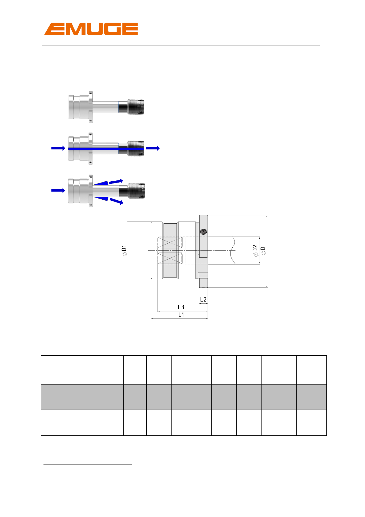
1.4.1 Type HE, HE-IKZZ, HE-IKZ, for taps/cold-forming taps
Type HE:
Without internal coolant-lubricant supply
Type HE-IKZZ:
With internal coolant-lubricant supply through
the tap/cold-forming tap axis
Type HE-IKZ:
With internal coolant-lubricant supply along the
tap/cold-forming tap shank
Picture 1: Dimensions of the quick-change adapters HE, HE-IKZZ, HE-IKZ
Table 1: Technical data of the quick-change adapters HE, HE-IKZZ, HE-IKZ
Type
Cutting
range
D
[mm]
D1
[mm]
D2
[mm]
[inch]
L1
[mm]
L2
[mm]
L31
[mm]
GB
Typ2
HE 2
M24 - M76 *
98
75
18-56
75
12
53-66
DIN
M24 - M76 **
18-56
53-66
ISO
1“–2 1/2
0,80–2,25“
43-66
ASME
HE 3
M36 - M160
128
90
28-70
110
15
76-98
DIN
M39 - M100
28-56
76-98
ISO
13/8 –3 1/2
1,11-2,81“
37-92
ASME
* Fine threads until M120x4 possible
** Fine threads until M100 possible
1
Plug-in depth is defined by the clamping diameter
2
Tool dimensions acc. to DIN or ISO or ASME

HE
Operating instruction edition: 01.02.2017 7
1.4.2 Type HE-MK, for drill and countersink
Picture 2: Dimensions of quick-change adapters HE-MK
Table 2: Technical data of quick-change adapters HE-MK
Type
For holders:
D
[mm]
D1
[mm]
Internal taper
acc.
DIN 228 B
L1
[mm]
L2
[mm]
L3
[mm]
HE 2–MK
HF 20
98
75
MK 3
75
20
25
MK 4
48
MK 5
80
HE 3-MK
HF 30
128
90
MK 4
110
15
20
MK 5
50
MK 6
115
For further dimensions please refer to the EMUGE main catalogue.
Internal taper according to
DIN 228 B

HE
8 Operating instruction edition: 01.02.2017
2 Putting the quick-change adapters into operation
2.1 Unpacking
- Take the quick-change adapter from the plastic case.
- Clean the quick-change adapter with a duster to remove any conservation oil.
Note
Do not use any aggressive solvents.
Do not use fibrous materials i.e. steel wool.
The quick-change adapter is now ready for operation
2.2 Insert tool
2.2.1 Insert tap / cold-forming tap
Attention
Choose the appropriate quick-change adapter for the required tap/cold-forming tap!
Note
Required tool: Type HE 2: Hexagon socket wrench: width across flats 4
Type HE 3: Hexagon socket wrench: width across flats 5
1. Push tap/cold-forming tap
into the quick-change
adapter.
Note
Bring the square into the
correct position by
turning the tap/cold-
forming tap.
√
Tap/cold-forming tap
Screws for tightening the tap/cold-forming tap
Quick-change adapter
HE
Operating instruction edition: 01.02.2017 9
2. Tighten all three screws
equally.
tap/cold-forming tap is
locked at the shank
Insert the quick-change adapter into the quick-change tap holder as described in the
operating instruction of the used quick-change tap holder.
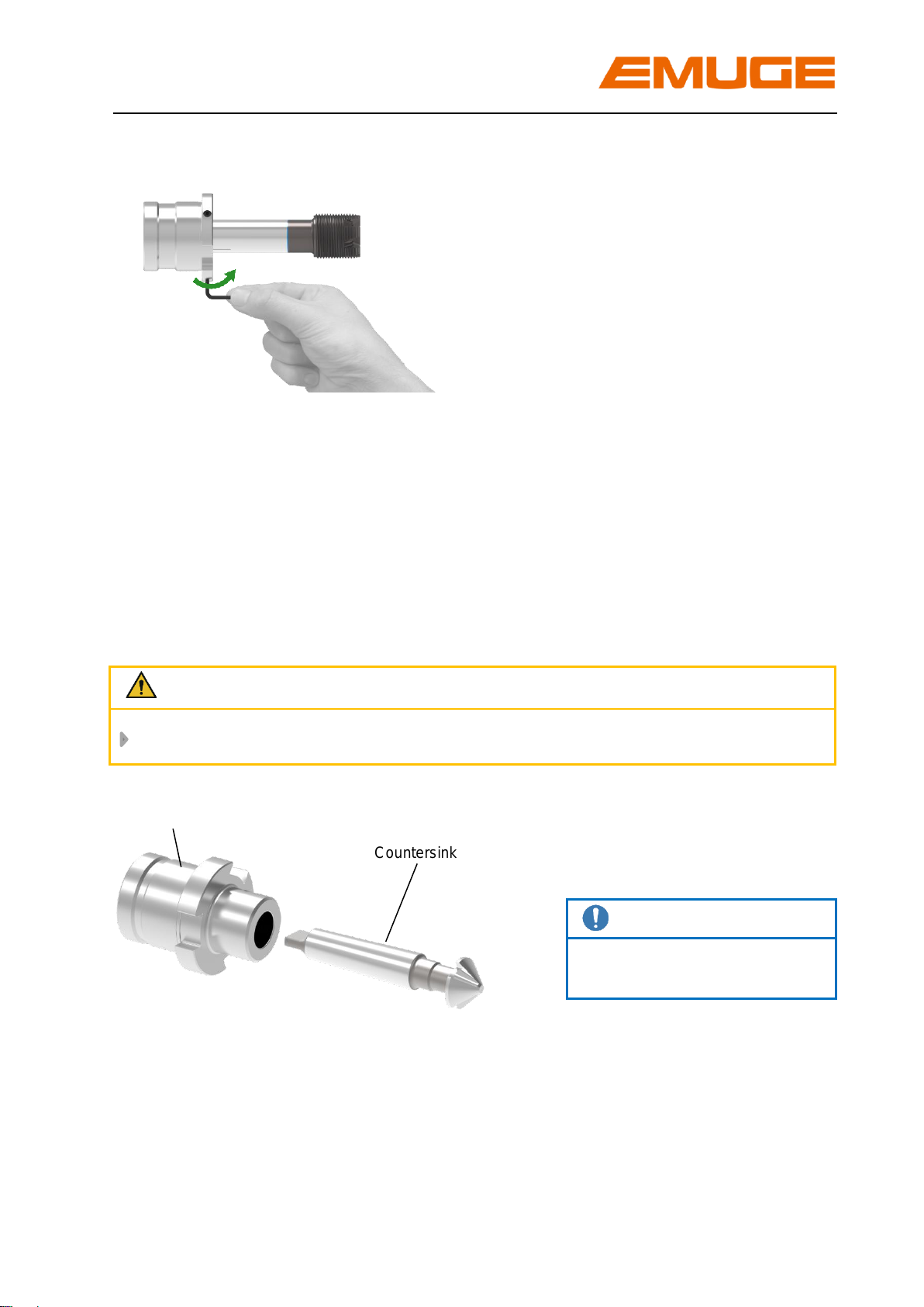
2.2.2 Insert drill or countersink
Attention
Choose appropriate quick-change adapter for required drill or countersink!
Strongly push in drill or
countersink.
Note
Watch position of the tang!
Now insert the quick-change adapter into the quick-change tap holder as described
in the operating instruction of the used quick-change tap holder.
Countersink
Quick-change adapter

HE
10 Operating instruction edition: 01.02.2017
2.3 Detach tool
2.3.1 Detach tap / cold-forming tap
Note
Required tool: Type HE 2: Hexagon socket wrench: width across flats 4
Type HE 3: Hexagon socket wrench: width across flats 5
1. Loosen all three
screws
2. Pull out tap/cold-
forming tap
2.3.2 Detach drill or countersink
Note
Required tool: Drift punch
Hammer
Use hammer and
drift punch to drive
out drill or
countersink
Tap/cold-forming tap
Quick-change adapter
Screws for tightening the tap/cold-forming tap
Hammer
Countersink
Drift punch
drift
Quick-change adapter

HE
Operating instruction edition: 01.02.2017 11
3 Maintenance
3.1 Maintenance schedule
What?
When?
Who?
External cleaning
Periodically, depending on the degree of
dirt.
Operator
3.2 External cleaning
Clean the quick-change adapter at periodic intervals depending on how dirty the
adapter is.
Note
Do not use any aggressive solvents.
Do not use fibrous materials i.e. steel wool.
4 Storage when not in use
If the quick-change adapter is taken out of service, please go through the following
working steps:
1. Clean the quick-change adapter with a duster, see chapter 3.2
2. Spray the quick-change adapter with a preservation oil to avoid rusting and to
preserve the easy running of the adapter
Attention
Before storage all evidence of coolant-lubricant and machining residues must be
removed!

EMUGE quick-change adapter HE
Operating instruction
Article number: ZB10011.GB 10575177
Original in German, Edition: 4, last change: 01.02.2017, change stage: 3
Please keep this for future use!
EMUGE-Werk Richard Glimpel GmbH & Co. KG
Fabrik für Präzisionswerkzeuge
Nürnberger Straße 96-100
91207 Lauf
GERMANY
+49 9123 186-0
+49 9123 186-230
info@emuge-franken.com www.emuge-franken.com
This manual suits for next models
4
Table of contents


