EMX WEL-200T User manual

COMMONLY USED 5FETY SENSORS
Installation Steps:
=
I
NOTE: DO NOT
Photocell (Reector)
CSING Direction
IMPORTANT: Photocell MUST be in alignment with
reflector or fault will occur.
OK to
use
12VDC
Photocell (Reector)
CSING Direction
IMPORTANT: Photocell MUST be powered by
MATRIX Ill or it will NOT be MONITORED.
Installation Steps:
23

Photocell (Thru-Beam) CLOSING Direction
Single Gate Operator
Transmitter
(TX) Receiver
(RX)
Single
Operator
CLOSING direction Thru-Beam
Gate Closed
emx irb-mon
IMPORTANT: Photocells MUST be powered
by Matrix III or they will NOT be MONITORED.12VDC OUT
Polarity does NOT matter
NC
NO NCCOM
COM NO
RX
POWER
INPUT
JUMPER EARTH
GND
SENSITIVITY
TX
POWER INPUT
TRANSMITTER
BOARD (TX)
ON DIP
1 2 3 4
RECEIVER
BOARD (RX)
Sensitivity Adjustment:
If the photocell does not
respond to an obstruction,
lower the sensitivity by
turning adjustment
counter-clockwise.
Transmitter (TX) Receiver (RX)
PHOTO CLS NC - Normally Closed
GND - Common
NO ComNC
Green
LED
To PHOTO CLS NC
and 12VDC OUT Input
To Matrix III
12VDC OUT Input
TX
RX
Jumper
Green
LED
NOTE: To meet the UL 325 2018standard, Type B1
Non-Contact sensor entrapment protection device
MUST be MONITORED by the gate operator.
Installation Steps:
1. Set DIP-switches on receiver.
2. Install jumper on receiver.
3. Wire Matrix III 12VDC OUT
power to receiver.
4. Wire PHOTO CLS NC
to receiver photocell NC.
Wire Matrix III GND to
receiver photocell COM.
5. Wire 12V Matrix III
power to transmitter.
6. Align photocells.
7. Adjust sensitivity on receiver. Jumper MUST be on Com-NC.
DIP-switches:
1, 2, 3 are OFF.
Switch 4 is ON
If trouble occurs, try
turning switch 4 OFF.
NOTE: Power must be
cycled when switches
are changed.
IMPORTANT: Photocells MUST be
in alignment or fault will occur.
Green LED will remain ON receiver
when in proper alignment.
OPEN ONLY NC
OPEN ONLY 10K
PHOTO CLS NC
OPEN/CLS NC
GND
12VDC OUT
GND
CLS ONLY 10K
OPEN/CLS 10K
12VDC OUT
UL SENSOR N.C.UL SENSOR 10K
P
NSOR N.C
P
NSOR N.C
P
SOR N.
P
SOR N
SOR N
SOR N
OR N
OR N
OR
UL SEN
N
UL SEN
UL SEN
UL SEN
UL SE
UL SE
UL SE
L SE
L S
NOTE:
IMPORTANT:
DO NOT use 10K Resistor included with photocell.
4 5 6
C-1 NO1 NC1
LIGHT ON
SENSITIVITY
Min Max
DARK ON
Power
Set switch to
“LIGHT ON”
24 to 240 VAC
24 to 240 VDC
1
C-1
2
NO1
3
Sensitivity Adjustment:
If the photocell does not respond to an
obstruction, lower the sensitivity by
turning adjustment counter-clockwise.
OK to
use
12VDC
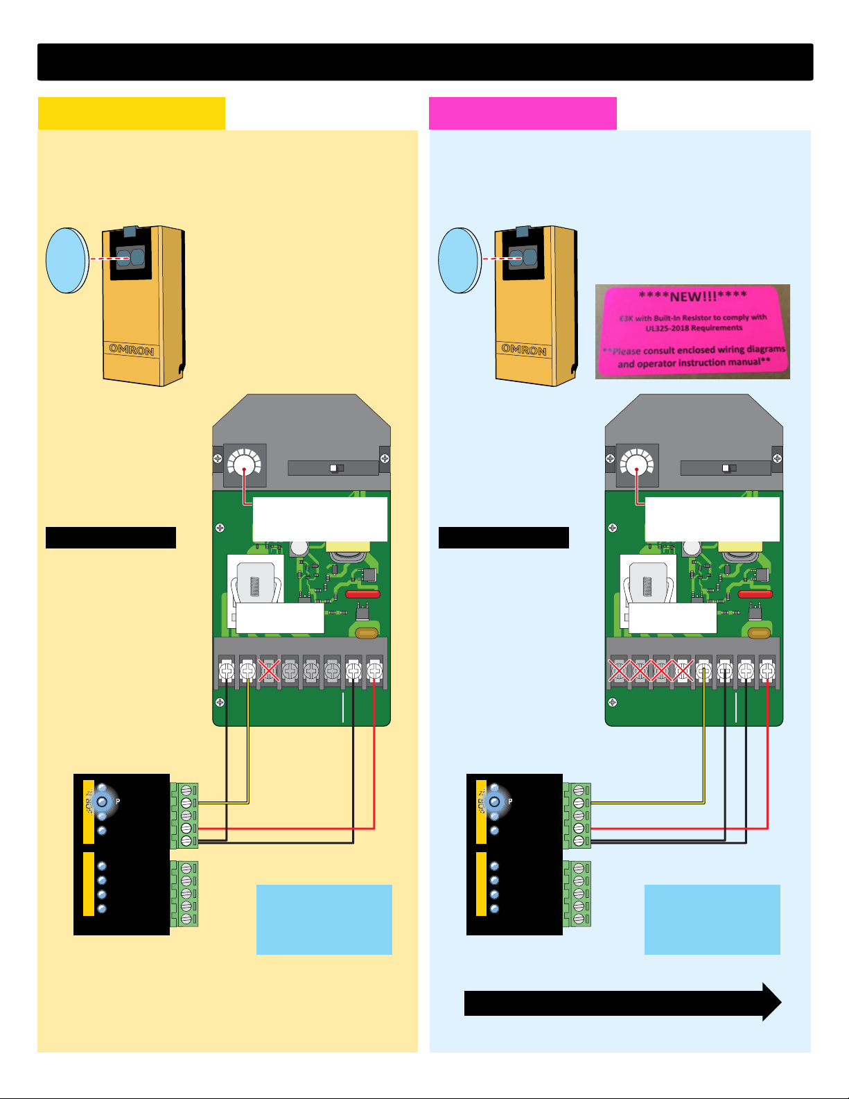
PHOTO CLS NC
GND
Photocell (Reflector)
CLOSING Direction
NOTE: To meet the UL 325 2016 standard,
Type B1 Non-Contact sensor entrapment
protection device MUST be MONITORED
by the gate operator.
Installation Steps:
1. Set switch to “LIGHT ON”
2. Wire 12V power to photocell
3. Wire PHOTO CLS NC
to photocell NO1
Wire GND to photocell C-1
4. Align photocell to reflector
5. Adjust sensitivity
omron E3K-R10K4 wiring for max pro
DO NOT connect
to NC1 #3.
OPEN ONLY NC
OPEN ONLY 10K
PHOTO CLS NC
OPEN/CLS NC
GND
12VDC OUT
GND
CLS ONLY 10K
OPEN/CLS 10K
12VDC OUT
UL SENSOR N.C.UL SENSOR 10K
NSOR N.C
P
NSOR N.C
P
SOR N.
P
SOR N
P
SOR N
SOR N
OR N
OR N
OR
Polarity doesNOT matter
12VDC Out Monitored
Polarity doesNOT matter
12VDC Out Monitored
45 6
C-1 NO1 NC1
LIGHT ON
SENSITIVITY
Min Max
DARK ON
Power
Set switch to
“LIGHT ON”
24 to 240 VAC
24 to 240 VDC
1 2
N02 C2
3
Sensitivity Adjustment:
If the photocell does not respond to an
obstruction, lower the sensitivity by
turning adjustment counter-clockwise.
OK to
use
12VDC
PHOTO CLS NC
GND
Photocell (Reflector)
CLOSING Direction
NOTE: To meet the UL 325 2018 standard,
Type B1 Non-Contact sensor entrapment
protection device MUST be MONITORED
by the gate operator.
Installation Steps:
1. Set switch to “LIGHT ON”
2. Wire 12V power to photocell
3. Wire PHOTO CLS NC
to photocell NO2
Wire GND to photocell C2
4. Align photocell to reflector
5. Adjust sensitivity
NORMALLY CLOSED (NC)
UL325-2018
Wiring to E3K Photocell
NORMALLY CLOSED (NC)
UL325-2016
Wiring to E3K Photocell
DO NOT connect
to NC2 #4.
OPEN ONLY NC
OPEN ONLY 10K
PHOTO CLS NC
OPEN/CLS NC
GND
12VDC OUT
GND
CLS ONLY 10K
OPEN/CLS 10K
12VDC OUT
UL SENSOR N.C.UL SENSOR 10K
NSOR N.C
P
NSOR N.C
P
SOR N.
P
SOR N
P
SOR N
SOR N
OR N
OR N
OR
NC2 N02 C2
Photocell MUST be powered
by 12VDC OUT Monitored or
it will NOT be MONITORED.
IMPORTANT:
Photocell MUST be powered
by 12VDC OUT Monitored or
it will NOT be MONITORED.
For 10K Resistor E3K Photocell wiring see next page
UL 2018 Label on packaging
Polarity doesNOT matter
4 5 6
C-1 NO1 NC1
LIGHT ON
SENSITIVITY
Min Max
DARK ON
Power
Set switch to
“LIGHT ON”
24 to 240 VAC
24 to 240 VDC
1
C-1
23
NC1
Sensitivity Adjustment:
If the photocell does not respond to an
obstruction, lower the sensitivity by
turning adjustment counter-clockwise.
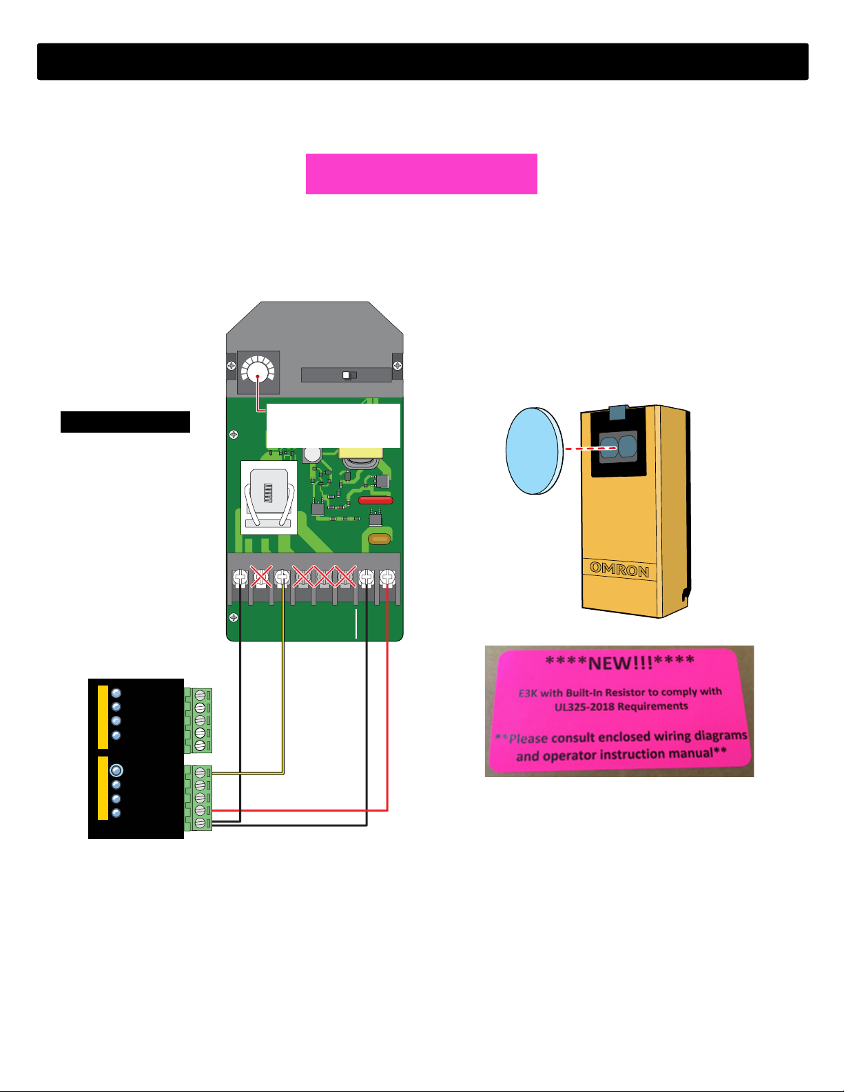
OK to
use
12VDC
GND
Photocell (Reflector)
OPENING Direction
NOTE: To meet the UL 325 2018 standard,
Type B1 Non-Contact sensor entrapment
protection device MUST be MONITORED
by the gate operator.
Installation Steps:
1. Set switch to “LIGHT ON”
2. Wire 12V power to photocell
3. Wire OPEN ONLY 10K
to photocell NC1
Wire GND to photocell C-1
4. Align photocell to reflector
5. Adjust sensitivity
10K Resistor wiring to E3K Photocell
UL325-2018
OPEN ONLY NC
OPEN ONLY 10K
PHOTO CLS NC
OPEN/CLS NC
GND
12VDC OUT
GND
CLS ONLY 10K
OPEN/CLS 10K
12VDC OUT
UL SENSOR N.C.
UL SENSOR 10K
P
P
P
P
12VDC OUT
NC2 N02 C2
omron E3K-R10K4 wiring for max pro
UL 2018 Label on packaging
OPENING
TRANSMITTER
WEL-200T WEL-200T
WEL-200R
WEL-200R
EMX
CLOSING
TRANSMITTER
RECEIVER
GND
OPEN ONLY NC
OPEN ONLY 10K
PHOTO CLS NC
OPEN/CLS NC
GND
12VDC OUT
GND
CLS ONLY 10K
OPEN/CLS 10K
12VDC OUT
UL SENSOR N.C.
UL SENSOR 10K
P
P
P
P
JP-2
10K
Jumper
JP-1
10K
Jumper
EXIT PWR
ALARM
POWER /
SOLAR IN
BATTERY
INPUT
OPENING CLOSING
CLOSINGOPENING
ERD
OBD PORT
BLACK BOX
PROGRAMMING
SOLAR MODE
PROGRAM
MOTOR
OVER
LOAD
ERD
MOTOR
OVER
LOAD MAX
OFF
MAX
SENSE MAX
SENSE
BATTERY
BACKUP MODE
ERD SENSITIVITY
MOTION CONTROL
OPEN
GATE SPEED
MAG
LOCK
UL
ENTRAP
PRIMARY/
SECONDARY
LINK
STOP CLOSE
MOTOR
INPUTS
CLOSE
TIMER
MAGLOCK
DELAY
JOG
BATTERY
TEST
INPUT
ERROR
BATTERY
BATTERY
IN USE
REPLACE
BATTERY LEAVE
CLOSED
LEAVE
OPEN
OPEN
1 TIME
BATTERY VOLTAGE
E F1/2
RESET /
MANUAL
RELEASE
ID
PLUG
LINK
OK
MODULE
PORT
MOTOR
POSITION
INPUTS
SLIDER
LIMIT
SWING
LIMIT
GND
OPEN ONLY NC
OPEN ONLY 10K
PHOTO CLS NC
OPEN/CLS NC
GND
12VDC OUT
GND
GND
GND
GND
GND
GND
JOG RIGHT
JOG LEFT
TAMPER IN
TAMPER NO
GATE DISABLE
MANUAL RELEASE
KEYPAD / CARD
GND
(-)
(+)
GND
GND
MAX OPEN
FIRE DEPT
RADIO GND
RADIO SIGNAL
STRIKE
CLOSE
COM
COM
STOP
OPEN
CLS ONLY 10K
OPEN/CLS 10K
12VDC OUT
NO
COM
NC
ID PLUG
ERROR
24VDC OUTPUT
12VDC OUTPUT
GND
GND
GND
LOOP PWR
OFF
PRIMARY
LEFT
ON/OFF
BATTERY
RIGHT
SECONDARY
ON
QUICK
CLOSE
OPEN
LEFT
OPEN
RIGHT
GATE
OFF
1
2
3
4
5
6
7
8
9
10
1
2
3
4
5
6
MIN MIN
MAX MAX
ON
OFF 2.5 sec
1.5 sec
FAULTS
OPERATOR
MATRIX III
OFF
OFF
3
1
14
16
MIN
16
MIN
12
9
7
3
1
14 12
9
7
UL SENSOR N.C.UL SENSOR 10K
POWER
MODE A MODE B
EXIT LOOP
LOOP
LOOP
CENTER
SAFETY
GATE OPEN
COM
GATE CLOSED
MIN
MATRIX III
SWING / SLIDE
www.max.us.com
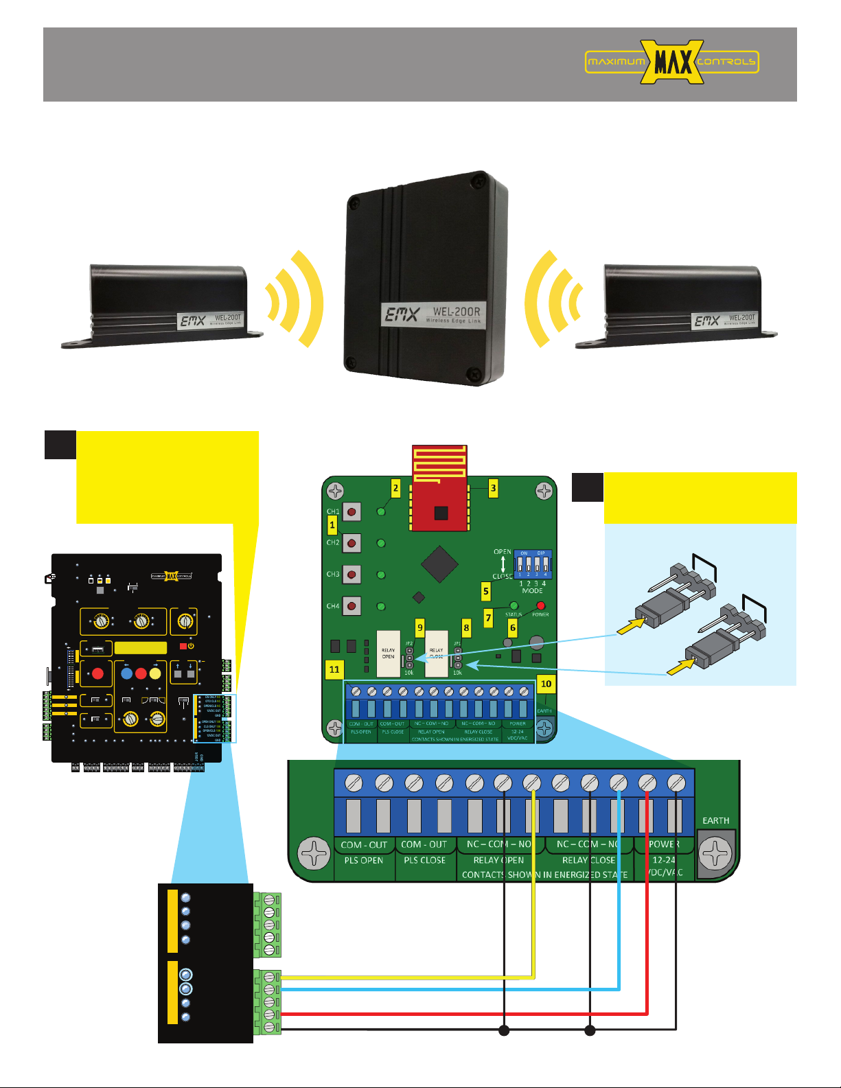
EMX WEL-200 Wiring Guide
FOR MAX PRO SERIES
WIRE WEL-200R
OPEN & CLOSE RELAYS
TO MATRIX III
10K SENSOR INPUTS
WIRE TO ‘NO’ OF RELAY OPEN
WIRE TO ‘NO’ OF RELAY CLOSE
1
INSERT BOTH JUMPERS
IN 10K POSITION
2
Polarity does
NOT matter
for power

Connecting is a two step process. First, on the receiver, press and hold the channel assignment switch until the green status LED
begins rapidly flashing, then release; this will clear any existing assignment for that particular channel. Hold down the
connection switch on the transmitter. If it is not currently connected to a receiver, it will begin flashing rapidly until successfully
connecting. Detailed instructions are given below.
EKdIf there are no existing connections, the receiver’s status LED will blink rapidly
while it is finding a clean operating frequency (this can last a few seconds)
After initialization, the system status LED will flash on/off once every 2 seconds
Set ĞĂĐŚchannel to the desired OPEN/CLOSE direction function using the MODE dip switch
/ĨĂ/WƐǁŝƚĐŚŝƐŝŶƚŚĞKWEƉŽƐŝƚŝŽŶƚŚĞŶƚŚĂƚĐŚĂŶŶĞůǁŝůůƚƌŝŐŐĞƌƚŚĞKWEZĞůĂLJŽŶ
ƌĞĐĞŝǀĞƌKƚŚĞƌǁŝƐĞŝƚǁŝůůƚƌŝŐŐĞƌƚŚĞ>K^ZĞůĂLJ
Install 2 AA Lithium batteries in the WEL-200T (transmitter)
The green LED on the transmitter will quickly flash 2x every two seconds
Install a properly terminated edge to the transmitter (8.2k or 10k termination)
On the receiver, hold down the desired channel assignment switch until all four channel
LED’s activate and the system status LED begins flashing rapidly, then release
the switch.
On the transmitter, hold down the connection switch (next to the terminal block)
The LED on the transmitter will begin flashing rapidly after ~4 seconds
Upon successful connection, the LED will flash once every two seconds
If the transmitter fails to connect, it will return to its initial state, with the
LED flashing twice every two seconds. If this occurs, repeat stepƐĂďŽǀĞ
1
2
3
4
5
WEL-200™ Operating Instructions 11
Document no. 10320104 Revision 2.0 3-1-18
Testing
Without activating the edge, observe the channel status LED, it should be OFF.
When the edge is activated, the receiver channel status LED will turn on and
the corresponding OPEN/CLOSE direction output will activate. The
transmitter status LED will blink once every second when the edge is activated.
If the channel does not exhibit this behavior, double check the edge
wiring/termination and transmitter batteries.
Notes
1. If channel 1 and 4 switches are pressed simultaneously during power up, the receiver will
perform a factory reset and clear all programmed channels.
2. Channel assignment mode will exit under the following conditions:
a. Successful connection to a transmitter
b. 60 second timeout
c. User selected exit
i. Pressing channel 1 and 4 switches simultaneously for more than 2 seconds
3. To remove a connection from the transmitter, hold down the connection button. The
LED will turn on solid for several seconds, and then blink twice every 2 seconds when
disconnected.
CONNECTING RECEIVER (WEL-200R) TO TRANSMITTER (WEL-200T)
STEPS
TESTING

EXIT PWR
ALARM
POWER /
SOLAR IN
BATTERY
INPUT
OPENING CLOSING
CLOSINGOPENING
ERD
OBD PORT
BLACK BOX
PROGRAMMING
SOLAR MODE
PROGRAM
MOTOR
OVER
LOAD
ERD
MOTOR
OVER
LOAD MAX
OFF
MAX
SENSE MAX
SENSE
BATTERY
BACKUP MODE
ERD SENSITIVITY
MOTION CONTROL
OPEN
GATE SPEED
MAG
LOCK
UL
ENTRAP
PRIMARY/
SECONDARY
LINK
STOP CLOSE
MOTOR
INPUTS
CLOSE
TIMER
MAGLOCK
DELAY
JOG
BATTERY
TEST
INPUT
ERROR
BATTERY
BATTERY
IN USE
REPLACE
BATTERY LEAVE
CLOSED
LEAVE
OPEN
OPEN
1 TIME
BATTERY VOLTAGE
EF1/2
RESET /
MANUAL
RELEASE
ID
PLUG
LINK
OK
MODULE
PORT
MOTOR
POSITION
INPUTS
SLIDER
LIMIT
SWING
LIMIT
GND
OPEN ONLY NC
OPEN ONLY 10K
PHOTO CLS NC
OPEN/CLS NC
GND
12VDC OUT
GND
GND
GND
GND
GND
GND
JOG RIGHT
JOG LEFT
TAMPER IN
TAMPER NO
GATE DISABLE
MANUAL RELEASE
KEYPAD / CARD
GND
(-)
(+)
GND
GND
MAX OPEN
FIRE DEPT
RADIO GND
RADIO SIGNAL
STRIKE
CLOSE
COM
COM
STOP
OPEN
CLS ONLY 10K
OPEN/CLS 10K
12VDC OUT
NO
COM
NC
ID PLUG
ERROR
24VDC OUTPUT
12VDC OUTPUT
GND
GND
GND
LOOP PWR
OFF
PRIMARY
LEFT
ON/OFF
BATTERY
RIGHT
SECONDARY
ON
QUICK
CLOSE
OPEN
LEFT
OPEN
RIGHT
GATE
OFF
1
2
3
4
5
6
7
8
9
10
1
2
3
4
5
6
MIN MIN
MAX MAX
ON
OFF 2.5 sec
1.5 sec
FAULTS
OPERATOR
MATRIX III
OFF
OFF
3
1
14
16
MIN
16
MIN
12
9
7
3
1
14 12
9
7
UL SENSOR N.C.UL SENSOR 10K
POWER
MODE A MODE B
EXIT LOOP
LOOP
LOOP
CENTER
SAFETY
GATE OPEN
COM
GATE CLOSED
MIN
MATRIX III
SWING / SLIDE
matrix III led troubleshooting
Table continued on next page
12. ID PLUG ERROR
15. EXIT LOOP
14. PRIMARY/SECONDARY
13. SOLAR MODE
5. POWER
6. ERD
7. MAX SENSE
8. MOTOR OVERLOAD
9. MANUAL RELEASE/RESET
20. CLOSE TIMER
21. SLIDER LIMIT
22. ON/OFF BATTERY
23. QUICK CLOSE
24. OPEN LEFT
25. OPEN RIGHT
26. GATE OPEN
27. GATE CLOSED
29. OPEN ONLY NC
30. PHOTO CLOSE NC
31. OPEN / CLOSE NC
32. 12VDC OUT
28. MAGLOCK
10. OBD PORT
11. PROGRAM
4. REPLACE BATTERY
3. BATTERY VOLTAGE
2. BATTERY IN USE
1. BATTERY INPUT ERROR
16. CENTER LOOP
17. SAFETY LOOP
18. 12 VDC
19. 24 VDC 33. OPEN ONLY 10K
34. CLOSE ONLY 10K
35. OPEN / CLOSE 10K
36. 12VDC OUT
37. UL ENTRAPMENT
42. GATE SPEED 40. LINK OK
41. MANUAL RELEASE
38. GATE TAMPER
39. GATE DISABLE
ID plug MUST be plugged in.
MAX
1500 PRO
MAX
2200 PRO
MAX
F18PRO
MAX 1500
MAX 2200
MAX F18
Matrix III LED
Problem Condition
Solution(s) for
Problem Condition
Normal
LED
“BATTERY IN ERROR” LED is ON.
“BATTERY IN USE” LED is ON
“BATTERY VOLTAGE (E 1/2 F)” LEDs, only “E”
is ON.
“REPLACE BATTERY” LED is ON.
“BATTERY IN USE” and “POWER” LED are
FLASHING
PRIMARY Matrix III “LINK OK” LED is OFF
SECONDARY Matrix III “LINK OK” LED is OFF
“UL Entrap” LED is ON
“ERD” LED is FLASHING
“PHOTO CLS” LED is ON
“CLS ONLY 10K” LED is ON
“PHOTO CLS” LED is flashing
“CLS ONLY 10K” LED is flashing
“OPEN ONLY” LED is ON
“OPEN ONLY” LED is FLASHING
“MAX SENSE” LED is ON
“MANUAL RELEASE/RESET” LED is ON but
manual release is not working
“OBD PORT” LED is FLASHING
“PROGRAM” LED is FLASHING
•“BATTERY Plug” not plugged in to “BATTERY IN” port.
•AC power is lost, operator is in battery back-up mode.
•Check if Toroid box AC POWER ON/OFF SWITCH is ON.
•Measure power input DC voltage on Matrix 1 (“24V/GND” - 2-pin black connector), (expected reading
34 VDC if AC on, 25VDC if on battery back-up).
•Battery is very LOW. Check if AC power ON/OFF switch is ON. If so, check AC power.
•Battery needs to be replaced if BATTERY TEST fails and “REPLACE BATTERY” LED is ON.
•Battery not plugged in to BATTERY INPUT port.
•Check if limit sensors are plugged into PRIMARY MATRIX III “SLIDER LIMIT” input.
•Check wiring between PRIMARY RS485 (+,-, gnd) and SECONDARY RS485 (+,-, gnd) terminals,
connect [(+) to (+)], [(-) to (-)] and [GND to GND].
•Check if limit sensors are plugged into SECONDARY Matrix III “SLIDER LIMIT” input.
•An entrapment event has occurred, check if an entrapment sensor was triggered (see if PHOTO CLS,
OPEN ONLY, or OPEN/CLS LEDs are on).
•An ERD event may have occurred. Check for gate obstruction.
•ERD sensitivity is too high for application. Re-adjust ERD setting, (see ).
•Sensor on PHOTO CLS or CLS ONLY 10K inputs (photocell or edge) may have detected an obstruction
while closing gate.
•Photocell on PHOTO CLS or CLS ONLY 10K inputs is misaligned with reflector.
•
Sensor on PHOTO CLS or CLS ONLY 10k inputs (photocell or edge) may not be wired properly, (see ).
•Sensor is NOT a N.C. monitored sensor that is UL325 2018compliant.
•Sensor might need to be re-learned.
•Sensor is damaged or malfunctioning.
•Sensor on OPEN ONLY input (photocell or edge) may have detected an obstruction while cycling gate.
•Photocell on OPEN ONLY input is misaligned with reflector.
•Sensor on OPEN ONLY input (photocell or edge) may not be wired properly, (see ).
•Sensor is NOT a N.C. monitored sensor that is UL325 2018compliant.
•Sensor on OPEN ONLY is damaged or malfunctioning.
•Sensor might need to be re-learned.
•MOST sensitive setting for ERD entrapment detection. Select a less sensitive setting (recommend level
10 thru 16)
•Connected external device to MANUAL RELEASE input is not working, check wiring. replace device.
•Up to 8000 event history and error codes are being downloaded to connected flash drive. Up to 5 min.
•Program button has been pressed and programming mode is active. Press button again to leave
programming mode.
1
OFF
2
OFF
3
OFF
4
OFF / ON
2 / 5
ON
40
ON
40
ON
37
ON
6
OFF
30 / 34
OFF
30 / 34
OFF
29 / 33
OFF
29 / 33
OFF
7
OFF
9 / 41
OFF
10
OFF
11
8
5
5

matrix III led continued
Matrix III LED
Problem Condition
Solution(s) for
Problem Condition
Normal
LED
“ID PLUG” LED is FLASHING and board beeping
“SOLAR MODE” LED is ON
“OPEN/CLS” LED is ON
“OPEN/CLS” LED is FLASHING
“MOTOR OVERLOAD” LED is ON
“EXIT” LOOP LED is FLASHING or
constantly ON
“SAFETY” LOOP LED is FLASHING or
constantly ON
“GATE DISABLE” LED is ON
“MAG LOCK” LED is FLASHING
“GATE TAMPER” LED is FLASHING
“12VDC” LED is OFF. “24VDC” LED is OFF
“SLIDER LIMIT” LED is ON
“ON/OFF BATTERY” LED is OFF
“QUICK CLOSE” LED is ON
“GATE SPEED” LEDs are ON but gate moves
slowly.
•Insert ID PLUG module that is tethered to chassis into “ID PLUG” connector.
•Operator is being powered by solar panel ONLY.
•Sensor on OPEN/CLS input (photocell or edge) may have detected an obstruction while opening or
closing gate.
•Photocell on OPEN/CLS input is misaligned with reflector.
•Sensor on OPEN/CLS input (photocell or edge) may not be wired properly, (see ).
•Sensor is NOT a N.C. monitored sensor that is UL325 2018compliant.
•Sensor on OPEN/CLS is damaged or malfunctioning.
•Sensor might need to be re-learned.
•Check if gate is binding against catch post or bracket in opened or closed position.
•Check if gate moves manually with low resistance throughout its full range of motion.
•Check if chain is installed inline with idle wheels in both OPEN and CLOSED positions.
•Loop fault condition: Check if EXIT loop wires are connected into to loop input connector properly.
•Check if loop detector is inserted properly in Loop Rack slot.
•Set unique loop detector frequency for each loop detector used.
•Loop Detector might be defective. Replace defective loop detector.
NOTE: RENO loop detector LED’s flash as default, but function normally (ignore the flashing).
•Loop fault condition: check if SAFETY loop wires are connected into to loop input connector properly.
•Check if SAFETY loops are wired in series.
•Check if loop detector is inserted properly in Loop Rack slot.
•Set unique loop detector frequency for each loop detector used.
•Loop Detector might be defective. Replace defective loop detector.
NOTE: RENO loop detector LED’s flash as default, but function normally (ignore the flashing).
•Check if “Gate Shut-off” switch is ON, Turn it OFF. If it is OFF, cycle the switch (ON then OFF).
• Check if the chain is dropped. If so, gate is disabled for safety. Re-install chain and cycle the "Gate
Shut-off" switch (ON then OFF) to enable operator.
•Check if an external device is triggering GATE DISABLE input. Disconnect devices individually to
determine possible false triggering of GATE DISABLE.
•Maglock power is lost. Check if maglock power transformer is wired properly or needs to be replaced.
•Switch is set to delay but no maglock is connected. Set switch to OFF
•Gate was manually moved off of its CLOSED position causing Tamper Relay to trigger for few seconds.
•Check for a short in wiring to connected device. DO NOT power external keypads or telephone entry to
this port (only use for radio receiver / photocell).
•Only ON if factory installed plug is plugged in. Re-install plug into SWING LIMIT connection for swing
gate operator.
•Batteries are turned OFF. Turn toroid box AC POWER switch ON and batteries automatically turn ON.
•Quick Close feature is turned ON. If this feature is not desired, turn quick close OFF.
• Check if OPEN and CLOSE Limits have been learned. Refer to “Learn Gate Positions” (see ).
•ONLY Maximum settings will turn LEDs ON. All other settings, LEDs remain OFF.
OFF
12
OFF
13
OFF
31
OFF
8
OFF
15
OFF
17
OFF
35
OFF
28
OFF
34
ON
18 or 19
OFF
21
ON
22
OFF
23
ON
42
5
7
This manual suits for next models
2
Table of contents
Other EMX Receiver manuals

Popular Receiver manuals by other brands


Daniels Electronics Ltd.
Daniels Electronics Ltd. OST-3H035 instruction manual

Fly Sky
Fly Sky FTr10 quick start guide

W Box Technologies
W Box Technologies HD2s user guide

BOSSCO
BOSSCO Therm RF Series installation instructions

One Forall
One Forall SV-1725 instruction manual

Icom
Icom IC-R8600 Service manual