ENCLO Belmont User manual
ASSEMBLY
INSTRUCTIONS
www.encloscreens.com
45 min
Approximate assembly time
Scan the QR code
for an assembly video
VER. 120523
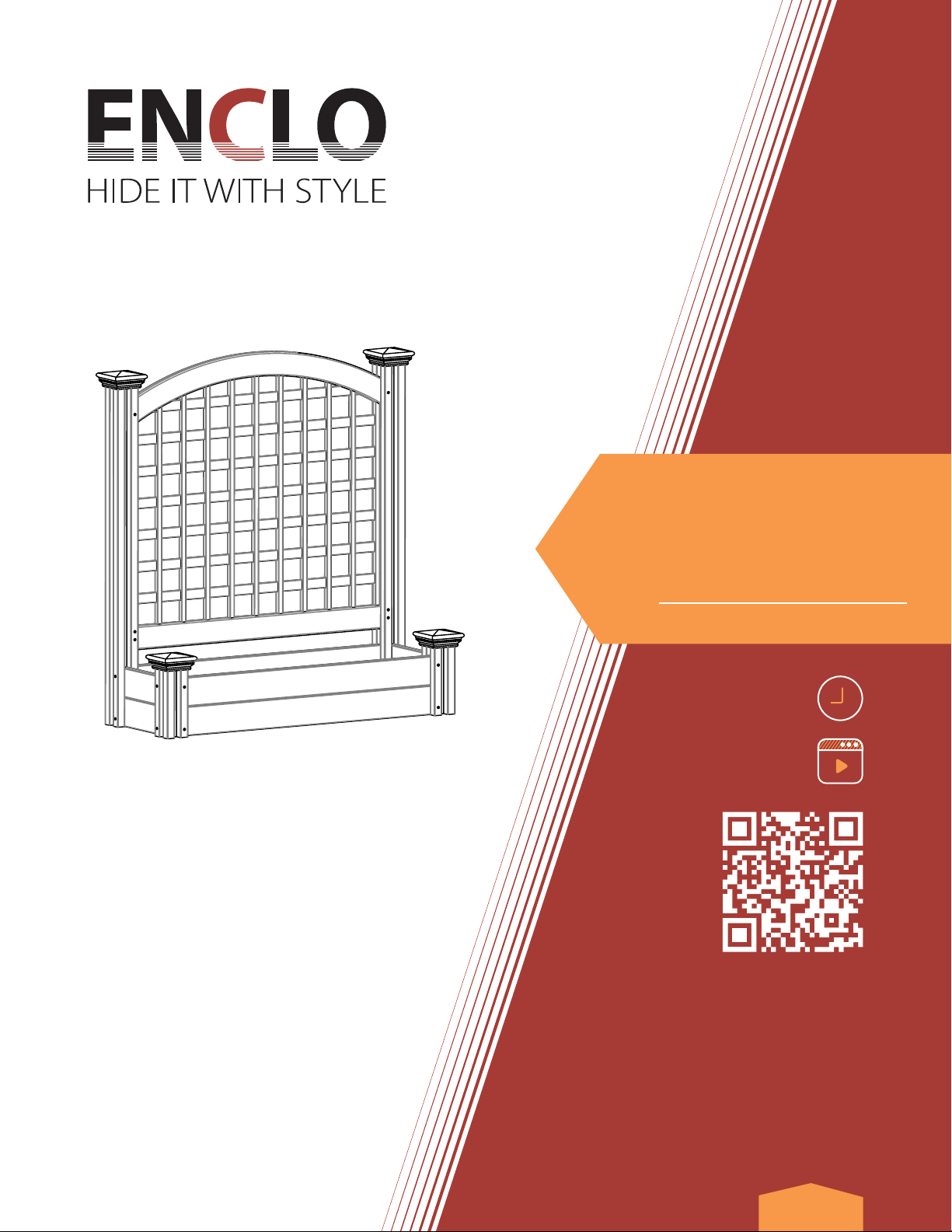
Belmont
Freestanding
Lattice Screen
W/ Planter Box
45 1/2"H X 42" W X 14 7/8" L
www.encloscreens.com
ASSEMBLY INSTRUCTIONSEC18032
2
jA cordless drill with a Phillips head bit will be requried for the
assembly of this product.
jCheck the inside of the larger pieces in your box for other
materials packed inside.
jWhen assembling components, place on a non-abrasive surface
(i.e. shipping box) to avoid scratching.
jWe recommend an area approximately 5’x 8’for unobstructed
assembling.
jYou should not need to use excessive force when assembling
components.
VISIT OUR WEBSITE FIRST,
SO WE CAN HELP YOU RIGHT AWAY!
Although great care has been taken to ensure proper packaging
and handling of this product, occasionally problems occur. If you
discover any missing, damaged or defective parts, please visit our
website to order replacement parts. If you experience any further
trouble with your product, please contact our customer service
department.
parts.nychbrands.com
suppor[email protected]om
704-892-5222 /877-234-6196
Customer service agents are available to take calls weekdays from 9am-
5pm EST. If you call outside of business hours, please leave a voicemail.
To help you quickly and accurately, please have reference item
number EC18032 and the specic part name which can be found
on page 4. It is helpful if you can provide the batch lot which is a
stamped number on the end of the box.
If you are having problems with the assembly or installation of this
product, we are happy to assist you with the process, so please give
us a call at 704-892-5222 / 877-234-6196.
If for some reason you need to return this product, please allow
us to help resolve your issues rst. If you still decide to return the
product, you will need to initiate the return from the company
you originally purchased from.
GENERAL
INFORMATION
MISSING OR
DAMAGED PARTS?
NEED ASSEMBLY HELP?
NEED TO RETURN?
IMPORTANT
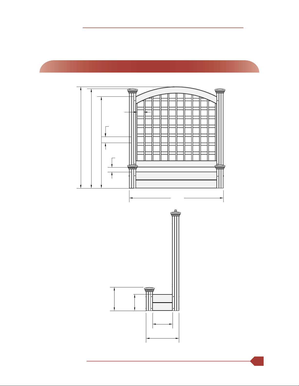
Detailed Product Dimensions & Specifications
www.encloscreens.com
ASSEMBLY INSTRUCTIONS EC18032
3
45 1/2 in
41 in
2 3/4 in
3 in
2 in
44 1/2 in
42 in
10 1/2 in
7 1/4 in
14 7
/
8 in
8
7
/
8 in
Planter Box Volume
30 quarts
Planter Box Depth
4.7 in
www.encloscreens.com
ASSEMBLY INSTRUCTIONSEC18032
4
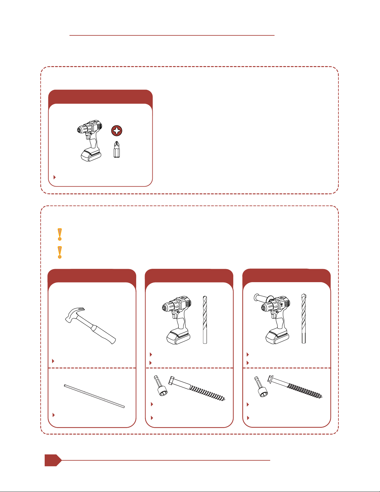
RECCOMENDED TOOLS
Power Drill with Phillips Bit
SURFACE MOUNTED INSTALLATION OPTIONAL
PRODUCT ASSEMBLY
DIRT
¾" Rebar (2)
Hammer
DECK
¼" Lag Screws
3" Length (4)
Matching Driver Bit Matching Driver Bit
Wood Drill Bit Concrete Drill Bit
Power Drill
PATIO
¼" Concrete Screws
2¼" Length (4)
Hammer Drill
Reccomended if installing into
high wind environment
Surface mounting screws
not included
RECCOMENDED TOOLS
www.encloscreens.com
ASSEMBLY INSTRUCTIONS EC18032
5
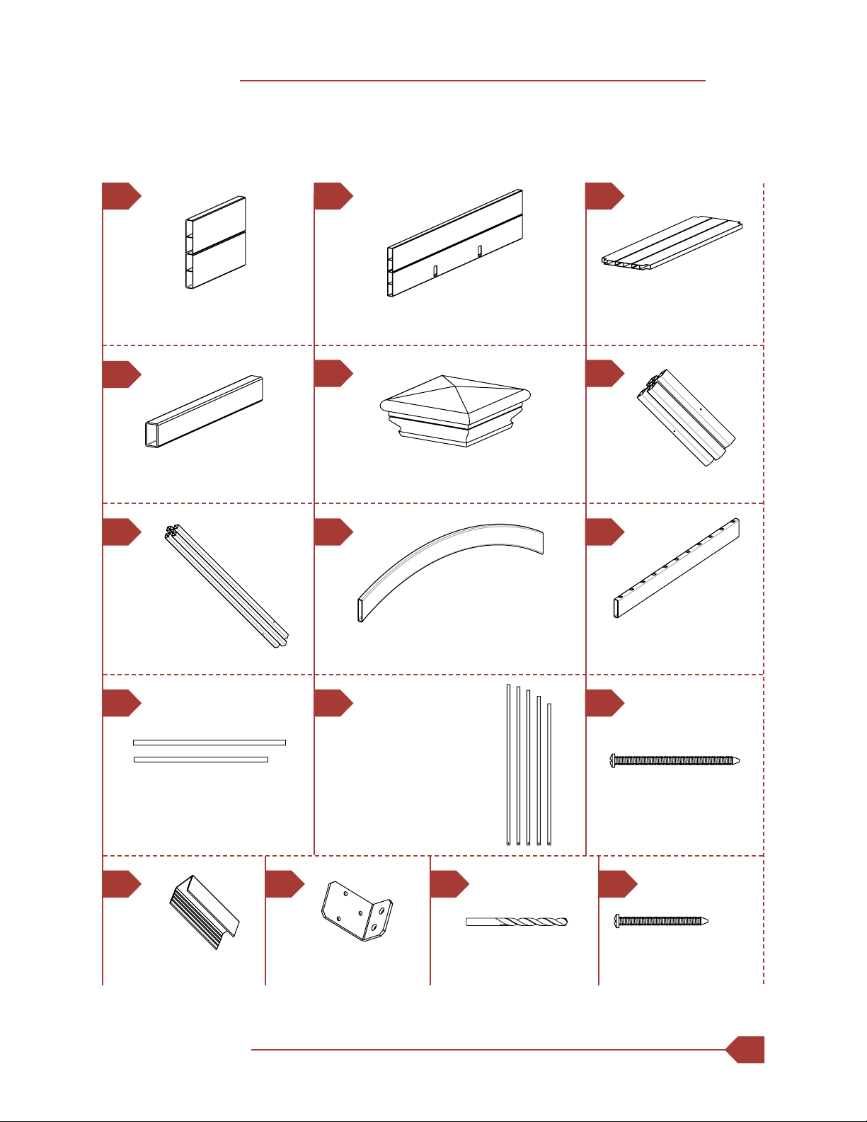
STEP 1: LAY OUT MATERIALS
A B C
Long Post (2)
3" x 3" x 44"
Arched Top Rail (1)
⁄" x 8½" x 38"
Bottom Rail (1)
⁄" x 3" x 38"
J K L
Spacer (2)
¾" x 1" x 2"
1½" Self-Drilling
Stainless Steel Screw(6)
M
Floor Support (2)
⁄" x 1½" x 7" Post Cap (4)
Short Post (2)
3" x 3" x 10"
G H I
Horizontal Slat (7)
Slat 1 (6) ¼" x 1¼" x 38"
Slat 2 (1) ¼" x 1¼" x 33½"
Vertical Picket (11)
Picket 1 (3) ⁄" x ⁄" x 35½"
Picket 2 (2) ⁄" x ⁄" x 35"
Picket 3 (2) ⁄" x ⁄" x 34¼"
Picket 4 (2) ⁄" x ⁄" x 33"
Picket 5 (2) ⁄" x ⁄" x 31½"
2½" Self-Drilling
Stainless Steel Screw (12)
E
DF
Side Board (2)
⁄" x 10⁄" x 7¼"
Long Board (2)
⁄" x 7¼" x 38"
Floor Board (1)
⁄" x 11" x 38"
Galvanized Steel L
Bracket (2)
N P
⁄ Drill Bit (1)
O
www.encloscreens.com
ASSEMBLY INSTRUCTIONSEC18032
6
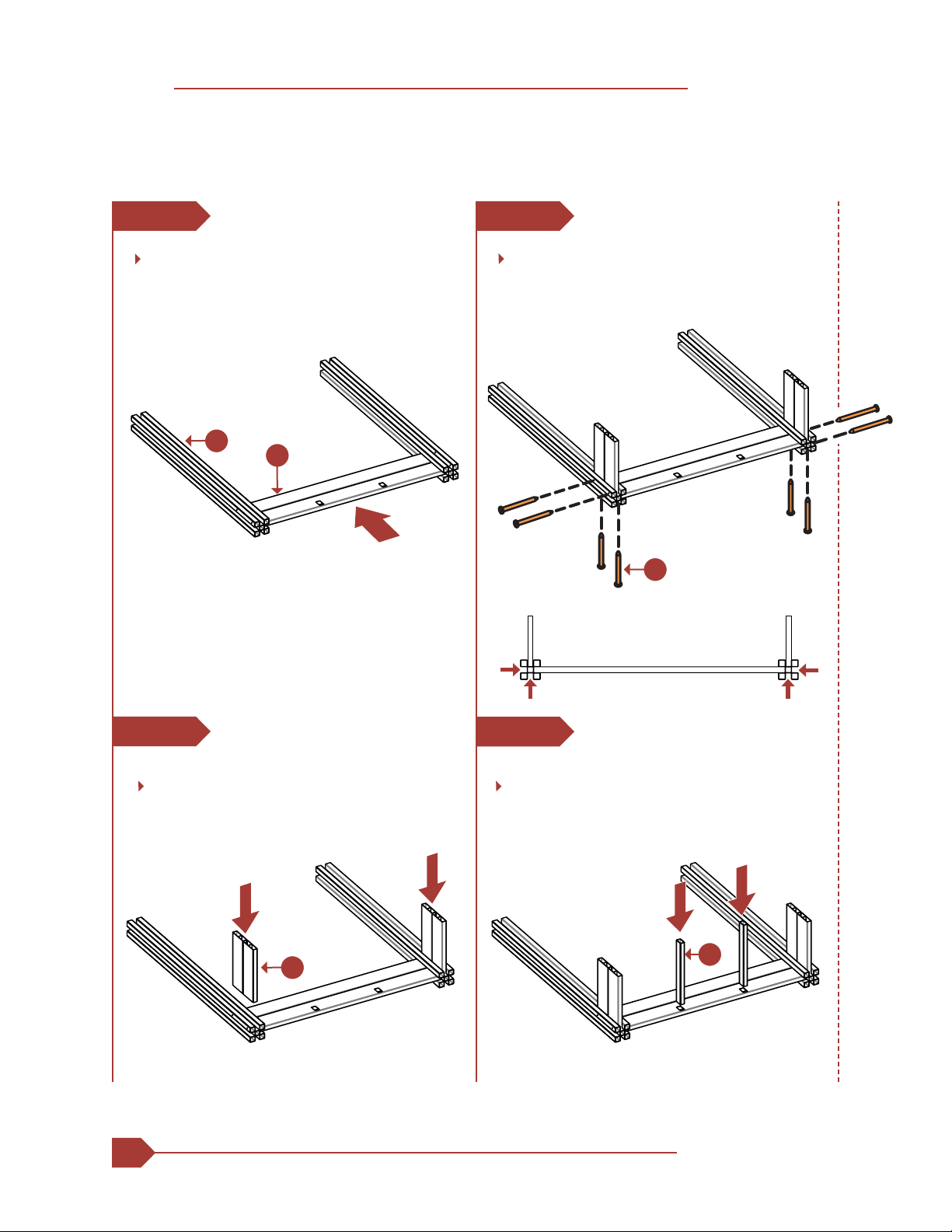
STEP 2: ASSEMBLE PLANTER BOX
STEP 2.1
STEP 2.2
STEP 2.3
STEP 2.4
AD
B
G
G
Ensure that the boards are touching
the back of the post channels before
installing screws
Drive (8) 2 ½" Self-Drilling Stainless
Steel Screws (L) through the pre-drilled
holes in the posts as shown below.
Lay out the Long Posts (G). Align the posts
so the pre-drilled holes match what is shown
in step 2.3 and slide (1) Long Board (B) into
the post channels as shown.
Slide (2) Side Boards (A) into the post
channels as shown.
Insert (2) Floor Supports (D) into the
long board as shown.
www.encloscreens.com
ASSEMBLY INSTRUCTIONS EC18032
7
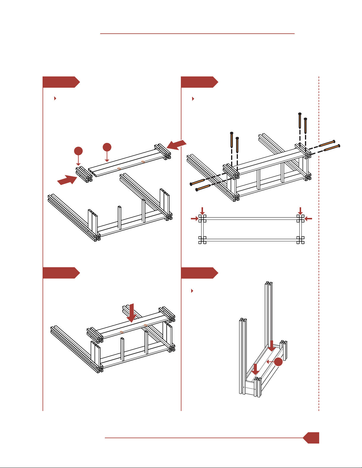
STEP 2.5
STEP 2.6
STEP 2.7
STEP 2.8
C
B
F
Ensure that the boards are touching
the back of the post channels before
installing screws
Align (2) Short Posts (F) so the pre-drilled
holes match what is shown in step 2.7
and slide (1) Long Board (B) into the post
channels as shown.
Drop (1) Floor Board (C)
into the planter box frame.
Drive (8) 2 ½" Self-Drilling Stainless
Steel Screws (L) through the pre-drilled
holes in the posts as shown below.
www.encloscreens.com
ASSEMBLY INSTRUCTIONSEC18032
8
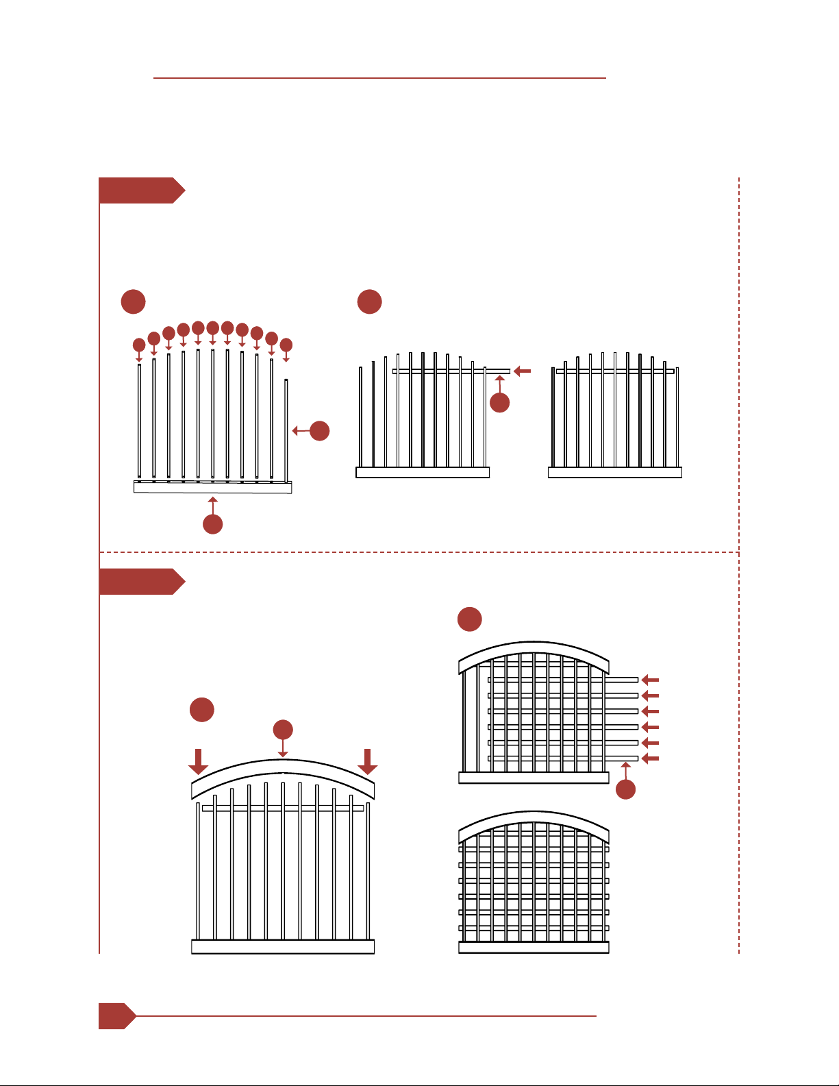
1. Insert the Vertical Pickets (K) into the Bottom Rail (I) in the pattern shown.
2. Insert the shorter Horizontal Slat 2 (J) into the top routed picket holes.
1. Install the Arched Top Rail (H) over the
vertical slats and horizontal slat 2.
2. Insert (6) horizontal slat 1 pieces into
the routed holes in the vertical pickets.
STEP 3: ASSEMBLE LATTICE SECTION
STEP 3.1
STEP 3.2
I
5 5
4 4
3 3
2 2
1 1 1
J
21
J
H
2
1
K

www.encloscreens.com
ASSEMBLY INSTRUCTIONS EC18032
9
1. Slide (2) Spacers (M) into the inner post channels of the long posts
as shown.
2. Slide the assembled lattice section into the inner post channels of
the long posts.
1. Pre-drill holes for (6) screws in the locations shown, with the
included ⁄" drill bit (O).
2. Drive (6) 2½" self-drilling stainless steel screws into the back of the
tall posts as shown below to secure the lattice section.
3. Remove spacers after screws have been installed.
2
2
1
1
STEP 4: INSTALL LATTICE SECTION
STEP 4.1
STEP 4.2
O
M

www.encloscreens.com
ASSEMBLY INSTRUCTIONSEC18032
10
OR OR
DIRT
STEP 6
¾" Rebar (2)
Hammer
DECK
STEP 7
¼" Lag Screws
3" Length (4)
Matching Driver Bit
Wood Drill Bit
Power Drill
PATIO
STEP 7
¼" Concrete Screws
2¼" Length (4)
Matching Driver Bit
Hammer Drill
SURFACE MOUNTED INSTALLATION OPTIONAL
Surface mounting screws
not included
Recommended if installing into
high wind environment
Concrete Drill Bit
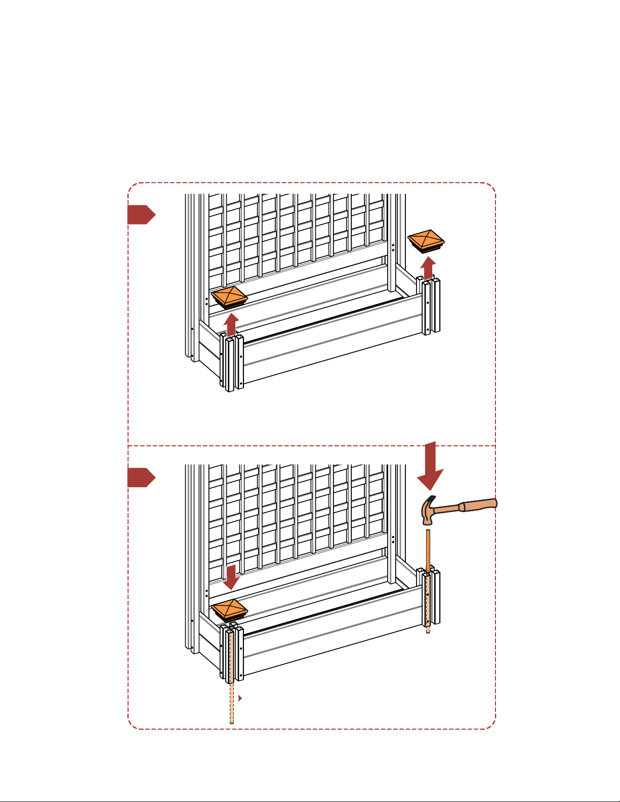
STEP 5: INSERT POST CAPS
STEP 5.1
Note: If you would like to
secure your post caps, apply a
small amount of vinyl glue to
the inside rim of the caps to x
them to the posts.
Fit (4) Post Caps (E) over
the short and tall posts.
E
17
6.1
6.2
Recommended if installing into
high wind environment
STEP 6: DIRT INSTALLATION OPTIONAL
¾" Rebar
(Not Included)

7.1
7.2
N
Recommended if installing into
high wind environment
STEP 7: PATIO / DECK INSTALLATION OPTIONAL
x3
P

(mounting screws
not included)
Repeat steps
for left side
Drill and install
mounting screws
according to instructions
on screw packaging
7.3
7.4

www.encloscreens.com
704-892-5222
877-234-6196
6935 Reames Rd. Ste. K.
Charlotte, NC 28216
ASSEMBLY
INSTRUCTIONS
VER. 120523
support@encloscreens.com
Other ENCLO Outdoor Furnishing manuals


Popular Outdoor Furnishing manuals by other brands


Factoryfurniture
Factoryfurniture Straight TREE Bench Operation & maintenance manual

Dura Trel
Dura Trel Cambridge Trellis 11172 Assembly instructions

Hay
Hay Palissade series instruction manual

bauhaus
bauhaus GFA30014B manual
Arrow Storage Products
Arrow Storage Products FKPS01 Owner's manual & assembly guide

U-Line
U-Line H-6570 Assembly instructions


