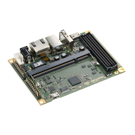
Enclustra Mercury+ ST1 User manual

Mercury+ ST1 Base Board
User Manual
Purpose
The purpose of this document is to present the characteristics of Mercury+ ST1 base board to the user, and
to provide the user with a comprehensive guide to understanding and using the Mercury+ ST1 base board.
Summary
This document first gives an overview of the Mercury+ ST1 base board followed by a detailed description of
its features and configuration options. In addition, references to other useful documents are included.
Product Information Code Name
Product ME-ST1 Mercury+ ST1 Base Board
Document Information Reference Version Date
Reference / Version / Date D-0000-456-001 02 23.07.2020
Approval Information Name Position Date
Written by HMEY, NALI Design Engineer 07.05.2020
Verified by HMEY Design Expert 11.05.2020
Approved by DIUN Manager, BU SP 23.07.2020
Enclustra GmbH – Räffelstrasse 28 – CH-8045 Zürich – Switzerland
Phone +41 43 343 39 43 – www.enclustra.com

Copyright Reminder
Copyright 2020 by Enclustra GmbH, Switzerland. All rights are reserved.
Unauthorized duplication of this document, in whole or in part, by any means is prohibited without the prior
written permission of Enclustra GmbH, Switzerland.
Although Enclustra GmbH believes that the information included in this publication is correct as of the date
of publication, Enclustra GmbH reserves the right to make changes at any time without notice.
All information in this document is strictly confidential and may only be published by Enclustra GmbH,
Switzerland.
All referenced trademarks are the property of their respective owners.
Document History
Version Date Author Comment
02 23.07.2020 HMEY Added information on the MIPI interfaces, added product pictures
and weight, other minor corrections and additions.
01 09.06.2020 HMEY Version 01, preliminary
D-0000-456-001 2 / 48 Version 02, 23.07.2020

Table of Contents
1 Overview 5
1.1 General ................................................... 5
1.1.1 Introduction ................................................ 5
1.1.2 Warranty .................................................. 5
1.1.3 RoHS .................................................... 5
1.1.4 DisposalandWEEE ............................................ 5
1.1.5 Safety Recommendations and Warnings . . . . . . . . . . . . . . . . . . . . . . . . . . . . . . . . 5
1.1.6 ElectrostaticDischarge .......................................... 6
1.1.7 Electromagnetic Compatibility . . . . . . . . . . . . . . . . . . . . . . . . . . . . . . . . . . . . . . 6
1.2 Deliverables ................................................ 6
1.3 Accessories................................................. 7
2 Getting Started 8
3 Board Description 9
3.1 BlockDiagram............................................... 9
3.2 Features................................................... 10
3.3 Board Configuration and Product Codes . . . . . . . . . . . . . . . . . . . . . . . . . . . . . . . . 10
3.4 Article Numbers and Article Codes . . . . . . . . . . . . . . . . . . . . . . . . . . . . . . . . . . . 11
3.5 TopandBottomViews .......................................... 12
3.5.1 TopView .................................................. 12
3.5.2 BottomView ................................................ 13
3.6 Top and Bottom Assembly Drawings . . . . . . . . . . . . . . . . . . . . . . . . . . . . . . . . . . 14
3.6.1 TopAssemblyDrawing .......................................... 14
3.6.2 BottomAssemblyDrawing........................................ 15
3.7 BoardDimensions............................................. 16
3.8 MechanicalData.............................................. 17
3.9 MechanicalComponents......................................... 17
4 Connectors Description 18
4.1 12VExternalPower(J1701)........................................ 18
4.2 12VInternalPower(J1700)........................................ 18
4.3 FanConnector(J1601)........................................... 19
4.4 I/OVoltageSelection(J1602)....................................... 19
4.5 Mercury Module Connector (J200/J201/J300) . . . . . . . . . . . . . . . . . . . . . . . . . . . . . 19
4.6 USB3.0HostConnector(J602) ..................................... 20
4.7 USB 3.0 Device Connector (J600) . . . . . . . . . . . . . . . . . . . . . . . . . . . . . . . . . . . . 20
4.8 Micro USB 2.0 Device Connector (J601) . . . . . . . . . . . . . . . . . . . . . . . . . . . . . . . . . 20
4.9 Gigabit Ethernet Ports (J1101/J1102) . . . . . . . . . . . . . . . . . . . . . . . . . . . . . . . . . . . 20
4.10 SFP+Connector(J1100).......................................... 20
4.11 MIPIConnectors(J1000/J1001)...................................... 20
4.12 HDMIConnector(J1300) ......................................... 21
4.13 Mini DisplayPort Connector (J1200) . . . . . . . . . . . . . . . . . . . . . . . . . . . . . . . . . . . 21
4.14 microSDCardSlot(J900)......................................... 21
4.15 FMCConnector(J1400).......................................... 21
4.16 FMCJTAGConnector(J1506)....................................... 22
4.17 Anios I/O Connector IO0/IO1 (J1501/J1505) . . . . . . . . . . . . . . . . . . . . . . . . . . . . . . . 23
4.18 I/O Connectors IO2/IO3/IO4 (J1500/J1504/J1507) . . . . . . . . . . . . . . . . . . . . . . . . . . . 23
4.19 BatteryHolder(J1600)........................................... 24
4.20 FPGAJTAGConnector(J1502) ...................................... 24
5 Power 26
5.1 PowerInput ................................................ 26
5.2 PowerGenerationOverview ....................................... 26
5.3 MaximumPowerBudget......................................... 27
D-0000-456-001 3 / 48 Version 02, 23.07.2020

5.4 PowerSequencing............................................. 27
5.5 PowerEnable/PowerGood........................................ 28
5.6 I/OVoltageSelection ........................................... 28
6 Board Function 32
6.1 LEDs..................................................... 32
6.2 Buttons ................................................... 32
6.3 DIPSwitches ................................................ 33
6.4 Ethernet................................................... 33
6.5 USB ..................................................... 34
6.5.1 USBOverview ............................................... 34
6.5.2 USB 2.0 Device Controller (FTDI) . . . . . . . . . . . . . . . . . . . . . . . . . . . . . . . . . . . . . 35
6.6 I2CCommunication............................................ 36
6.7 HDMI .................................................... 38
6.8 DisplayPort................................................. 39
6.9 MIPI..................................................... 39
6.10 ClockArchitecture............................................. 41
6.10.1 ClockGenerator.............................................. 42
7 Operating Conditions 43
7.1 AbsoluteMaximumRatings ....................................... 43
7.2 Recommended Operating Conditions . . . . . . . . . . . . . . . . . . . . . . . . . . . . . . . . . 43
8 Ordering and Support 44
8.1 Ordering .................................................. 44
8.2 Support................................................... 44
A Appendix 48
D-0000-456-001 4 / 48 Version 02, 23.07.2020

1 Overview
1.1 General
1.1.1 Introduction
The Mercury+ ST1 base board is equipped with a multitude of I/O connectors for use with Mercury family
FPGA and SoC modules. The board is well-suited for rapid prototyping and for building FPGA systems,
without the need for developing custom hardware.
The board can also be used for production flash programming on Mercury modules, or for educational
purposes.
This board is specially designed for image processing applications.
The main features of the Mercury+ ST1 base board are:
•Support for USB 3.0 host and USB 3.0 device
•FTDI USB 2.0 High-Speed device controller
•High-speed FPGA and flash programming over USB
•FMC HPC Connector
•Versatile set of I/O connectivity options
•2×Ethernet RJ45 connectors
•SFP+ connector
•2×MIPI D-PHY interfaces (CSI , CSI/DSI)
•HDMI 2.0a connector
•Mini DisplayPort connector
•Low-jitter clock generator
•microSD card slot
•Simple integration by using a single 12 V voltage supply
•Small solution size
1.1.2 Warranty
Please refer to the General Business Conditions, available on the Enclustra website [1].
1.1.3 RoHS
The Mercury+ ST1 base board is designed and produced according to the Restriction of Hazardous Sub-
stances (RoHS) Directive (2011/65/EC).
1.1.4 Disposal and WEEE
The Mercury+ ST1 base board must be properly disposed of at the end of its life. If a battery is installed on
the board, it must also be properly disposed of.
The Waste Electrical and Electronic Equipment (WEEE) Directive (2002/96/EC) is not applicable for the Mer-
cury+ ST1 base board.
1.1.5 Safety Recommendations and Warnings
Mercury boards are not designed to be “ready for operation” for the end-user. Proper configuration of the
hardware before usage is required.
D-0000-456-001 5 / 48 Version 02, 23.07.2020

Ensure that the power supply is disconnected from the board before inserting or removing a Mercury mod-
ule, connecting interfaces, or connecting jumpers.
Touching the capacitors of the DC-DC converters can lead to voltage peaks and permanent damage; over-
voltage on power or signal lines can also cause permanent damage to the board and to the equipped
module.
Warning!
It is possible to mount some Mercury modules the wrong way round on the Mercury+ ST1 base board
- always check that the mounting holes on the base board are aligned with the mounting holes of the
module.
Every Mercury module has a 1 mm copper square module marker, which has its counter part on the
base board. If these module markers are aligned, proper orientation is granted. The copper square can
be found in a corner of the module, on top as well as on the bottom side.
The base board and module may be damaged if the module is mounted the wrong way round and
powered up.
Warning!
Certain older revisions of the Mercury KX1 FPGA module cannot be used in combination with Mercury+
base boards (with three module connectors), due to a mechanical collision caused by large capacitors
on the bottom side of the module.
Always check that the mounting holes on the base board are aligned with the mounting holes of the
Mercury+ ST1 base board. If the module cannot be mounted correctly due to the mechanical collision,
please contact Enclustra support.
1.1.6 Electrostatic Discharge
Electronic boards are sensitive to electrostatic discharge (ESD). Please ensure that the product is handled
with care and only in an ESD-protected environment.
1.1.7 Electromagnetic Compatibility
The Mercury+ ST1 base board is a Class A product (as defined in IEC 61000-3-2 standard) and is not in-
tended for use in domestic environments. The product may cause electromagnetic interference, for which
appropriate measures must be taken.
1.2 Deliverables
•Mercury+ ST1 base board including plastic standoffs
•Mercury+ ST1 base board documentation, available via download:
•Mercury+ ST1 Base Board User Manual (this document)
•Mercury+ ST1 Base Board IO Net Length Excel Sheet [3]
•Mercury+ ST1 Base Board User Schematics (PDF) [4]
•Mercury+ ST1 Base Board Known Issues and Changes [5]
•Mercury+ ST1 Base Board 3D Model (PDF) [6]
•Mercury+ ST1 Base Board STEP 3D Model [7]
•Module Pin Connection Guidelines [8]
•Mercury Master Pinout [9]
D-0000-456-001 6 / 48 Version 02, 23.07.2020

2 Getting Started
This section contains essential information on using the Mercury+ ST1 base board.
Before first use of the Mercury+ ST1 base board with a Mercury or Mercury+ module, the following steps
must be followed:
•Mount the module on the module slot on the base board, with the power switched off.
Warning!
It is possible to mount some Mercury modules the wrong way round on the Mercury+ ST1 base
board - always check that the mounting holes on the base board are aligned with the mounting
holes of the module.
Every Mercury module has a 1 mm copper square module marker, which has its counter part on
the base board. If these module markers are aligned, proper orientation is granted. The copper
square can be found in a corner of the module, on top as well as on the bottom side.
The base board and module may be damaged if the module is mounted the wrong way round
and powered up.
Warning!
Certain older revisions of the Mercury KX1 FPGA module cannot be used in combination with
Mercury+ base boards (with three module connectors), due to a mechanical collision caused by
large capacitors on the bottom side of the module.
Always check that the mounting holes on the base board are aligned with the mounting holes of
the Mercury+ ST1 base board. If the module cannot be mounted correctly due to the mechanical
collision, please contact Enclustra support.
•Set the DIP switches correctly (refer to Section 6.3).
•Set the I/O voltage selection jumpers correctly (refer to Section 5.6).
•Power up the board (refer to Section 5 for power options).
The power supply of the base board must be turned off in the following situations:
•Before changing the position of the I/O voltage selection jumpers
•Before removing the Mercury or Mercury+ module
•Before connecting or disconnecting peripherals to ANIOS and I/O connectors
•Before connecting or disconnecting FMC cards
Before connecting peripherals, make sure that the corresponding VCC_IO voltage is properly set.
The operating conditions for the Mercury+ ST1 base board and equipped module must conform to the
values given in Section 7, and in the relevant section from the Mercury or Mercury+ module user manual.
Warning!
The Mercury+ ST1 base board can only be used in combination with a Mercury or Mercury+ module.
When using the board without module the “PWGD” LED will remain off; refer to Section 6.1 for details.
D-0000-456-001 8 / 48 Version 02, 23.07.2020

3 Board Description
3.1 Block Diagram
The Mercury+ ST1 base board can be used in combination with any Mercury module. Depending on the
equipped module some features may not be available.
The block diagram of the Mercury+ ST1 base board is shown in Figure 1.
Figure 1: Hardware Block Diagram
D-0000-456-001 9 / 48 Version 02, 23.07.2020

3.2 Features
Table 1 describes the features available on the Mercury+ ST1 base board.
Feature Description
Form factor 120 ×100 mm
System features Built-in Xilinx JTAG (via USB connection)
Low-jitter clock generator
Programmable user oscillator (optional)
Memory microSD card holder
Connectors 2 ×USB 3.0 connectors (host & device)
2×RJ45 Gigabit Ethernet connectors
Micro USB (FTDI USB 2.0 High-Speed device controller)
Mini DisplayPort connector
SFP+ connector
FMC HPC connector
2×MIPI D-PHY connectors (CSI , CSI/DSI)
HDMI 2.0 connector
User I/Os 2 ×40-pin Anios pin headers
3×12-pin IO connectors
2×user push bottons
Supply voltage 12 V DC (internal, external)
Table 1: Base Board Features
Warning!
Please note that the available features depend on the equipped Mercury FPGA/SoC module.
3.3 Board Configuration and Product Codes
Table 2 describes the standard base board configuration. Custom configurations are available; please contact
Enclustra for further information.
Product Code Features Temperature Range
ME-ST1-W Refer to Table 1 -20..+75◦C
Table 2: Standard Base Board Configuration
D-0000-456-001 10 / 48 Version 02, 23.07.2020

3.4 Article Numbers and Article Codes
Every board is uniquely labeled, showing the article number and serial number. An example is presented in
Figure 2.
Figure 2: Product Label
The correspondence between article number and article code is shown in Table 3. The article code repre-
sents the product code, followed by the revision; the R suffix and number represent the revision number.
The revision changes and product known issues are described in the Mercury+ ST1 Base Board Known Issues
and Changes document [5].
Article Number Article Code
EN102868 MA-ST1-W-R1
Table 3: Article Numbers and Article Codes
D-0000-456-001 11 / 48 Version 02, 23.07.2020

3.6 Top and Bottom Assembly Drawings
3.6.1 Top Assembly Drawing
2 Apr 2020
Multi-Layer
Confidential
ME-ST1.PcbDoc
Copyright ©by Enclustra GmbH
14
20
22
28
10
16
20
22
24
28
5
7
13
19
21
27
1
7
9
15
19
21
23
27
-+
5
7
13
19
21
27
1
7
9
15
21
23
10
12
16
18
24
26
12
14
18
26
3
1
11
9
17
15
25
23
5
3
13
11
17
25
3
1
11
9
17
15
25
23
5
3
13
11
19
17
27
25
6
8
2
8
6
8
14
20
22
28
2
8
10
16
22
24
44
2
44
6
44
2
10
12
16
18
24
26
44
6
12
14
18
20
26
28
L1-Top
M1-PCB Outline
FID1809
C1782
C1761
D401
C1773 J1602 J1502
C1706
C1787
Q1601
C1762
R1515
D1605
D1604
D1606
D1607
D1500
D1501
R1501
FB600
C1715 R1503
R1506
FB602
C1732
R1404
D1400
C1763 C1711
L1702
R1618
R1704
C1703
C1702
D601
L1701
R608 R609
Q1700
R610
R604
R611
R605
C238
U511
U508
C239
C419
U500 C418
C1755
R704
D1600
C213
U504 U502
C227
U401
C1759
R512
U505 U503
R502
U507
R404
R403
R406
R405
U501 C1749
C217
C411 C1757
C233
C237
C230
C408
R1204
C234
Y400
R421
C402
R411
C409
C404
R424
R423
R425
R1205
C1206
R1200
C229
C231
C218
C401
C403
C1754
C224
C235
FB800
R801
D602
C501
C243
C244
C222
C1771
C1765
C1211
C1747 R705 D402
D1201
C1210
C1209
R805
C809
U800
R803 D1303
C1208
C1401 R804
C808
R802
Y800
C203
D1302
C1310
C1400
C1741
C1736 C207
C206
R904
R903
R1301
R1300
C1777
Y802
R807
C209
C200
C201
C1730
C303
C1731
R1512
R806
M1823
C304
C306
C1743
C1778
R1309
R1305
C1775
C1776
D1304
C1786
C1404
R1302
R1303
C1406 F1300 FB1305
C1405 C1729
FB1801
C1804
R1406
U901
C1802
C307
R1009 R1003 R901
R310
R311 R313
R312
R1011 R1002
R1001
R1020 R1027
D600
C1106
C1104
C606
C1108
FB1101
J1500
F1200
FB1200
Q900
M1819
C608
FB1201
C607
R614
J1504 J1507
J900
C900
J601
J1505 C603
FID1811
R1800
I1801
FID1812
M1800 M1803
Z1804
C1707 J1601
C1708 J1700 C1705
R1602
R1600
C1767 C1764 R1701 C1604 M1816
R420
R1613
C1719 R1702 C1700 C1709
R1614
R1612 C1723 C1717
R1616 C1712 R607R606 C604
C1750
R1615 R613R612
R603R602
C605
Q1603 R1705 FB1700
C1701 C602
C600
C1751
R504
C415
U707
R505 Q500
U506 R503
R500
U510
C1756
U706
R416
R417
C414 C413
C1737 R601
R600
R412
C417 R401
C1500 U1703
C1779 R413
R414
C416
R402
R418
C405 R1203
C1734
C1201
R1202
C801 C800
U705
Q501
R508
U509 R810
C807
C806
C1110
R1400
R1401
C241
C242
C1111
R1402
R1403 C1200
C1204 C1740
C212
C1205
C1207
FB1301
Z1838
C1304
C1739
FB1302
FB801 C803
C208
C1305
C1302
C802
C1300
C1303
FB802
C815 C814 C1742
C1301
C1306
C305
C1403 C1758 R1311
FB1402
U904
FB1401 R1405 R900
R1801
C301
U900
C309 C310
R1005 R1012 R905 C1753
R309
R308 R1006 R1013 R1025
C1105
FB1100
C1746
C1203 C1202
J1001
D1202
R1500R1502 R1507
R1508 R1510 U601 R1208
R1207
R1206
R1209
R907
M1801 M1802
I1803
I1800
J1501
F1700
R1513
R1201
FB1303
C1725 FB1300
C1409
C1408
C300
M1100
R1509
FB603
I1802
M1830
M1831
D1602
D1601
FID1807
J1600
M1813
R1605
M1821
M1814
R1407
Q1602Q1600
R1617
C1713
C1718
C1720
U1700
C1704
D1502
D1700
D603
M1815
C601
J600
U1701
C1721
D1701
C1710
R615
C1103
C1102
C215
C228
C1733
R501
R703
U701
C1600
C236
C214
R513
R409
R410
R407
R408
C410
D400
U403
R415
R702
R506
U702
C1101
C1100
C1728
R1103
R1100
J1400
C232
J201
R1706
C1752
U1200
C1783
U1201
C220
C210
J200
R906 C225 C221
C1113
C1112
C1748
R1110
R1109
U703
C406
FB400
FB401
C503
C502
R509
R511
C500
R800
C219
C226 C211
D1200
R507 C804
C805
C1735
U1702
C1785
U1704
C204
C202
C223
C216
R1308
C1772
C1774
C1800
C1766
C240
C311
C810
C811
R808
C302
M1817
U1300
D1300 D1301
J1300
C1407
C1402
C812
R1310
R1306
R1307
C1308
J1000
R1010
D1000
R1004 R1019
R1017
R1026
R1018
R1016
R1015
U902
FB605
J602
J1100
C1109
C1107
M1818
M1820
D1002
C1744
R902
R1514 C1760
C1601
S1600
C1603
R1108
R1101
R1105
R1104
R1107
R1102 Z1810
R1106 S1602
C1602
S1601
R1609
R1607
R1606
C1784
M1811
R908
R1014
M1812
C609
J1200
C1780 C1727
M1810
M1829
M1832
FID1801
FID1802
M1825
R1601
D1603 C1722 C1714
R1703
C1716
R1700 L1700
M1822
U600
FB1800
R1603
J1101
C412
U704
R701
R700
U700
R400
U400
R419
U402
R1210
C407
R510
Y801
J1102
C1781
R422 R809
R1707
C205
C816
Q1604
C1307
FB1400
C813
J300
R1024 R1008 R1021 R1304
FB1304
C1309
D1001
R1007
R1023
R316
C308
R1000
D1003
FB604
U903
R1611
C1770
Z1811
R1610
S1603
R1608
C1768C1745 C1769 C1738
C1801
M1826
FID1803
C1724
R1022
FB601
R1408
R1604
J1701
C1726
Pin 1
Z1845
M12-Assembly Top
R1511
Figure 5: Board Top Assembly Drawing
D-0000-456-001 14 / 48 Version 02, 23.07.2020

3.6.2 Bottom Assembly Drawing
L12-Bottom
FID1810
Z1849
Z1850
TP1600 TP1705 TP1504 TP601
TP205
M1824
TP1403 TP603
TP301
TP602
TP1102
TP1101
FID1813
FID1808
TP1701
TP300 TP202
TP204 TP203 TP1501
TP1503 TP200 TP600
TP1500TP1700
TP1707
TP1405 TP1400 TP1706
TP401
TP1708
TP1402
TP1800
FID1804
TP1703
TP1502TP1602
TP1702
TP1601
TP201
TP1404
TP500
TP1406
TP1100
FID1806
Z1851
Z1847
Z1848
M1809
Z1863.Designator
J1506
Z1841
TP1801
FID1805
FID1800
TP1401
TP400
TP1704 TP1300
Figure 6: Board Bottom Assembly Drawing
Please note that depending on the hardware revision and configuration, the base board may look slightly
different than shown in this document.
D-0000-456-001 15 / 48 Version 02, 23.07.2020

3.8 Mechanical Data
Table 4 describes the mechanical characteristics of the Mercury+ ST1 base board. A 3D model (PDF) and a
STEP 3D model are available [6], [7].
Symbol Value
Size 120 ×100 mm
Component height top 11.3 mm
Component height bottom 8 mm plastic standoffs equipped on bottom side
Weight 100 g (without battery and module)
Table 4: Mechanical Data
3.9 Mechanical Components
Table 5 describes the mechanical components present on the Mercury+ ST1 base board. The listed elements
are for reference only. Any other components that meet the requirements may be used.
Product Number Manufacturer Description
973080365 Würth Elektronik 4 ×plastic spacer bolt with female thread/clip, length 8 mm
Table 5: List of Mechanical Components
D-0000-456-001 17 / 48 Version 02, 23.07.2020

4 Connectors Description
4.1 12 V External Power (J1701)
This connector is used to supply the main VCC input voltage.
Apply only 12 V DC to this connector.
Pin Number Signal Name Description
1 (inner) VCC_MAIN_IN 12 V DC (nominal) input voltage
2 (outer) GND Ground
Table 6: J1701 - External Power Connector
Type Manufacturer
PJ-102AH CUI
Table 7: J1701 - External Power Connector Type
4.2 12 V Internal Power (J1700)
The Mercury+ ST1 base board base board can alternatively be powered through the internal power input
connector J1700. The 12 V DC power source connected to J1700 must be filtered by external power circuitry.
Apply only 12 V DC to this connector.
Pin Number Signal Name Description
1 VCC_MAIN 12 V DC (nominal) input voltage
2 GND Ground
Table 8: J1700 - Internal Power Connector
Type Manufacturer
292132-2 TE Connectivity
Table 9: J1700 - Internal Power Connector Type
Warning!
Do not short circuit the 12 V power supply, and make sure the currents flowing through the pins of this
connector do not exceed 2.0 A. Otherwise, the PCB may be damaged.
D-0000-456-001 18 / 48 Version 02, 23.07.2020

4.3 Fan Connector (J1601)
An external 12 V fan can be connected to J1601 connector.
Pin Number Signal Name Description
1 GND Ground
2 VCC_MAIN 12 V DC (nominal) input voltage
3 NC -
Table 10: J1601 - Fan Connector
Type Manufacturer
61900311121 Würth Elektronik
Table 11: J1601 - Fan Connector Type
Table 12 shows an example of a mating part for the fan connector. This connector is without female crimp
contacts or wires.
Type Manufacturer
61900311621 Würth Elektronik
Table 12: Mating Part for the Fan Connector
4.4 I/O Voltage Selection (J1602)
The I/O voltage selection jumpers are used to configure the VCC_IO_A, VCC_IO_B and VCC_IO_C voltages
that power the I/O banks of the SoC/FPGA device on the Mercury module. Refer to Section 5.6 for details.
4.5 Mercury Module Connector (J200/J201/J300)
A detailed pinout of the Mercury module connector can be found in the Mercury Master Pinout [9] and in
the Mercury+ ST1 Base Board User Schematics [4].
Warning!
Only Enclustra Mercury FPGA/SoC modules should be inserted into the Mercury+ ST1 base board.
Warning!
The VCC_IO pins are directly connected to the FPGA/SoC device. Apply only compliant voltages to
the VCC_IO pins; any other voltage may damage the mounted Mercury FPGA/SoC module, as well as
other devices on the Mercury+ ST1 base board.
D-0000-456-001 19 / 48 Version 02, 23.07.2020

4.6 USB 3.0 Host Connector (J602)
The Mercury+ ST1 base board is equipped with a type-A USB 3.0 host connector.
If the mounted Mercury module features a USB controller, the module’s USB signals can be connected to
J602 via a multiplexer. Details on USB connections on the board are available in Section 6.5.
The power and data signals on this connector are ESD-protected.
4.7 USB 3.0 Device Connector (J600)
The Mercury+ ST1 base board is equipped with a type-B USB 3.0 device connector.
If the mounted Mercury module features a USB controller, the module’s USB signals can be connected to
J600 via a multiplexer. Details on USB connections on the board are available in Section 6.5.
The power and data signals on this connector are ESD-protected.
4.8 Micro USB 2.0 Device Connector (J601)
The micro USB connector on the board is connected to the FTDI device. It can be used for UART, SPI and
I2C communication. Refer to Section 6.5.2 for details on the FTDI device.
4.9 Gigabit Ethernet Ports (J1101/J1102)
The Mercury+ ST1 base board is equipped with two 10/100/1000 Mbit Ethernet ports. The capability of the
Ethernet interface depends on the connected Mercury module.
The RJ45 connectors are connected through magnetics directly to the Mercury module connector. For
details on the Ethernet interface, refer to Section 6.4.
4.10 SFP+ Connector (J1100)
The Mercury+ ST1 base board is equipped with a SFP+ socket. The capability of the SFP+ interface depends
on the connected Mercury module as well as on the plugged SFP+ module.
The SFP+ connector J1100 is connected by default to the Mercury module connector C, pins C-63/65 (TX
side) and C-66/68 (RX side).
4.11 MIPI Connectors (J1000/J1001)
The Mercury+ ST1 base board is equipped with two MIPI connectors, each with 2 signal lanes. The signals
available on these connectors are routed to/from the FPGA banks on the SoC/FPGA device on the Mercury
module. Refer to section 6.9 for details on connectivity options.
The pinout on the J1000 and J1001 connectors corresponds to the Raspberry Pi pinout. In order to receive
and transmit video signals through the links, FPGA support is required (video protocol implementation).
The signals on the connectors are ESD-protected.
D-0000-456-001 20 / 48 Version 02, 23.07.2020
This manual suits for next models
1
Table of contents
Other Enclustra Motherboard manuals
Popular Motherboard manuals by other brands
Atmel
Atmel SAMA5D3 EK Series user guide
New Micros
New Micros NMIN-0812 manual

NGX Technologies
NGX Technologies BlueBoard Base user manual
Qianglongsheng Electronic Technology
Qianglongsheng Electronic Technology MCD-DEMO-II manual
Systium Technologies
Systium Technologies Ready 555 User's quick start guide

Infineon
Infineon iMOTION EVALM1CTE620N3TOBO1 user manual


