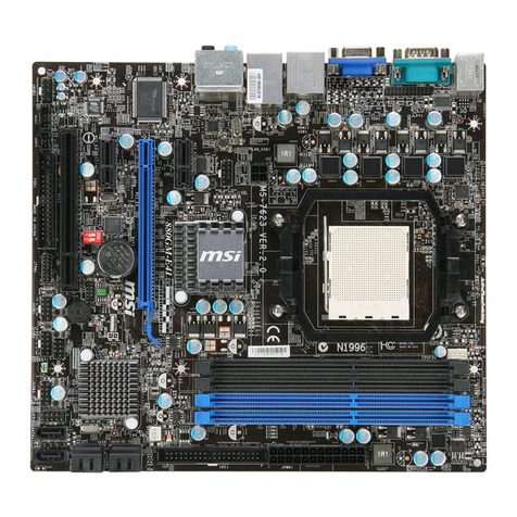
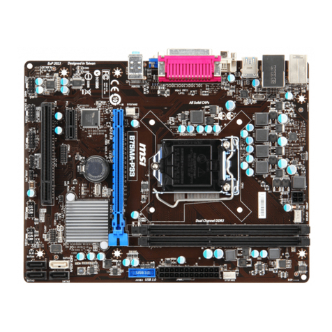
MSI RC410 Series User manual

i
RC410 Series
MS-7248(V1.X)Mainboard
G52-M7248X1
7248v1.0-Preface.p65 2006/1/16, 午 06:491

ii
CopyrightNotice
The materialinthisdocumentistheintellectual propertyof MICRO-STAR
INTERNATIONAL.Wetakeeverycareinthe preparationof thisdocument, butno
guaranteeisgivenastothecorrectnessofitscontents.Ourproductsareunder
continualimprovementand wereservetherighttomakechangeswithoutnotice.
Trademarks
Alltrademarksarethepropertiesoftheirrespectiveowners.
NVIDIA,theNVIDIAlogo,DualNet, and nForceareregisteredtrademarksortrade-
marksofNVIDIACorporationin theUnitedStatesand/orothercountries.
AMD,Athlon ,Athlon XP,Thoroughbred ,andDuron areregisteredtrade-
marksofAMDCorporation.
Intel®andPentium®areregisteredtrademarksofIntelCorporation.
PS/2and OS®/2areregisteredtrademarksofInternationalBusiness Machines
Corporation.
Windows®95/98/2000/NT/XPareregisteredtrademarksofMicrosoftCorporation.
Netware®isaregisteredtrademarkofNovell,Inc.
Award®isaregisteredtrademarkofPhoenixTechnologiesLtd.
AMI®isaregisteredtrademarkofAmericanMegatrendsInc.
RevisionHistory
Revision RevisionHistory Date
V1.0 Firstrelease January2006
TechnicalSupport
Ifaproblemariseswithyoursystemandnosolutioncanbeobtainedfromtheuser’s
manual,pleasecontactyourplaceofpurchaseorlocaldistributor.Alternatively,
pleasetrythefollowing helpresourcesforfurtherguidance.
Visit theMSI websiteforFAQ,technical guide,BIOSupdates,driverupdates,
andotherinformation: http://www.msi.com.tw/program/service/faq/
faq/esc_faq_list.php
Contactourtechnicalstaff at: support@msi.com.tw
7248v1.0-Preface.p65 2006/1/16, 午 06:492

iii
SafetyInstructions
CAUTION: Dangerofexplosionifbatteryisincorrectlyreplaced.
Replaceonlywiththe sameorequivalenttype recommendedbythe
manufacturer.
1. Alwaysread thesafetyinstructionscarefully.
2. KeepthisUser’sManualforfuturereference.
3. Keepthisequipmentawayfromhumidity.
4. Laythisequipmentonareliableflatsurfacebeforesetting itup.
5. Theopeningsontheenclosureareforairconvectionhenceprotectstheequip-
ment fromoverheating.DONOTCOVERTHEOPENINGS.
6. Makesurethevoltageofthe powersourceandadjustproperly110/220Vbe-
foreconnectingtheequipmenttothepowerinlet.
7. Placethe powercordsuchawaythatpeoplecannotstepon it. Donotplace
anythingoverthepowercord.
8. AlwaysUnplug thePowerCordbeforeinsertinganyadd-oncardormodule.
9. All cautionsand warningsontheequipmentshouldbenoted.
10. Neverpouranyliquidintotheopeningthatcoulddamage orcauseelectrical
shock.
11. If anyof thefollowing situationsarises, gettheequipmentcheckedbyaservice
personnel:
†Thepowercordorplugisdamaged.
†Liquid haspenetratedintotheequipment.
†Theequipmenthasbeen exposedtomoisture.
†Theequipmenthasnotworkwelloryoucannotgetitworkaccording to
User’sManual.
†Theequipmenthasdroppedand damaged.
†Theequipmenthasobvioussign of breakage.
12.DONOTLEAVETHISEQUIPMENTINANENVIRONMENTUNCONDITIONED,STOR-
AGETEMPERATUREABOVE600C(1400F),IT MAYDAMAGETHEEQUIPMENT.
7248v1.0-Preface.p65 2006/1/16, 午 06:493

iv
FCC-BRadio Frequency Interference Statement
Thisequipmenthasbeen
tested and found tocomply
withthe limitsforaClassB
digitaldevice,pursuanttoPart
15of the FCCRules.Theselimitsaredesignedtoprovidereasonable protection
againstharmful interferenceinaresidentialinstallation.Thisequipmentgenerates,
usesand canradiateradiofrequencyenergyand,ifnotinstalledand used in accor-
dancewiththeinstructions,maycauseharmful interferencetoradiocommunications.
However,thereisno guarantee thatinterferencewill notoccurin aparticular
installation.Ifthisequipmentdoescauseharmful interferencetoradioortelevision
reception,whichcanbedeterminedbyturning theequipmentoff and on,the useris
encouragedtotrytocorrecttheinterferencebyone ormoreof themeasureslisted
below.
†Reorientorrelocatethereceiving antenna.
†Increasetheseparationbetweentheequipmentand receiver.
†Connecttheequipmentintoanoutleton acircuitdifferentfromthatto
whichthereceiverisconnected.
†Consultthedealeroranexperiencedradio/televisiontechnicianforhelp.
Notice1
Thechangesormodificationsnotexpresslyapprovedbythepartyresponsible for
compliancecould void theuser’sauthoritytooperatetheequipment.
Notice2
Shieldedinterfacecablesand A.C.powercord,ifany,mustbeusedinorderto
complywiththeemissionlimits.
VOIRLANOTICED’ INSTALLATIONAVANTDERACCORDERAURESEAU.
Micro-StarInternational
MS-7248
ThisdevicecomplieswithPart15oftheFCCRules.Operationissubjecttothe
followingtwoconditions:
(1)thisdevicemaynotcauseharmfulinterference,and
(2)thisdevicemustaccept anyinterferencereceived,includinginterferencethat
maycauseundesiredoperation.
7248v1.0-Preface.p65 2006/1/16, 午 06:494

v
WEEE (WasteElectricaland ElectronicEquipment) Statement
7248v1.0-Preface.p65 2006/1/16, 午 06:495

vi
7248v1.0-Preface.p65 2006/1/16, 午 06:496

vii
7248v1.0-Preface.p65 2006/1/16, 午 06:497

1-1
Getting Started
Getting Started
Chapter1
ThankyouforchoosingtheRC410Series(MS-7248
v1.X) MicroBTXmainboard.TheRC410 Series
mainboardsarebasedon ATI RC410 & SB450 chipsets
foroptimalsystemefficiency.Designedtofitthe ad-
vancedIntel®Pentium4,CedarMill,and Celeron D
processors,the RC410Seriesdeliverahighperfor-
manceandprofessionaldesktopplatformsolution.

MS-7248Mainboard
1-2
ProcessorSupport
- SupportsLGA775Intel Pentium4,CedarMill,andCeleronDpro-
cessors
- Supports2005 performanceFMB05BCPUVRdesign
-Supports2005 mainstreamFMB05ACPUVRdesign (Optional)
SupportedFSB
-800/533MHz
Chipset
-NorthBridge: ATI RC410chipset
-SouthBridge:ATI SB450 chipset
MemorySupport
-DDRII 533/667SDRAM(2GBMax)
-2DDRIIDIMMs(240pin/1.8V)
LAN
-Supports10/100FastEthermetbyRealtekRTL8100C(Optional)
-Supports10/100/1000 GigabitLANbyRealtekRTL8110S(Optional)
IEEE1394
-ChipintegratedbyVIA VT6307(Optional)
-Transferrateisup to400Mbps
Audio
-ChipintegratedbyRealtek ALC861orALC880 (Optional)
-Flexible8-channelaudiowithjacksensing
-CompliantwithAzalia1.0Spec
IDE
-2IDEportsbyATISB450
-SupportsUltraDMA66/100/133 mode
-SupportsPIO,BusMasteroperationmode
SATA
-SATAportsbyATISB450
-SupportsfourSATAdevices
-Supportsstorage and datatransfersat up to1.5Gb/s
RAID
-SATA1~4supportsRAID0/1mode bySB450
Floppy
-1floppyport
-Supports1FDD with360K, 720K,1.2M,1.44Mand 2.88Mbytes
MainboardSpecifications

1-3
Getting Started
Connectors
Backpannel
-1PS/2mouseport
-1PS/2keyboardport
-1serialport(COM1)
-1parallelportsupporting SPP/EPP/ECPmode
-1IEEE 1394port
-4USB2.0ports
-1LANjack
-1VGA port
-1Line-In/Line-Out/MIC/CenterSpeakerOut/RearSpeakerOut/Side
Surroundaudioport
OnboardPinheaders
-1audiopinheader
-2USB 2.0pinheaders
-1CD-INpinheader
Slots
-1PCI Expressx16slot
-1PCI Expressx1slot
-2PCIv2.332-bitslots
FormFactor
-MicroBTX: 10.5”X10.4”
Mounting
-6mounting holes

MS-7248Mainboard
1-4
RC410Series(MS-7248v1.X) M-BTXMainboard
MainboardLayout
PCI2
PCI1
PCI_E2
RTL8100C/
RTL8110S
(Optional)
ALC861/
ALC880
(Optional)
Winbond
W83627EHG
BTX1
JLPC1
SYS_FAN
PCI_E1
ATI
SB450
BATT
+
IDE2
IDE1
SATA1
SATA2
SATA3
JCD1 JAUD1
JPWR1
DIMM2
DIMM1
SATA4
JUSB1
JUSB2
FDD 1
JFW1
VIA
VT6307
(Optional) JF_P1
CPU_FAN1
JCMOS
BIOS
Top: Mouse
Bottom: Keyboard
T: 10/100or GbLAN
Jack(Optional)
B: USB Ports
Top:
ParallelPort
Bottom:
VGAPort
COMA
T: 1394Port
B: USBPorts
ATI
RC410
T:C
M: RS
B:
S-Out
-Out
Side
Surround
T:Line-In
M: Line-Out
B:Mic
(Optional)
(Optional)
(Optional)

2-1
HardwareSetup
HardwareSetup
Chapter2
Thischapterprovidesyou withtheinformation about
hardwaresetupprocedures.Whiledoingthe installation,
becarefulinholdingthecomponentsandfollowthe
installationprocedures.Forsomecomponents,ifyou
install inthewrong orientation,thecomponentswillnot
workproperly.
Useagroundedwrist strapbeforehandlingcomputer
components.Staticelectricitymaydamagethe
components.

MS-7248Mainboard
2-2
Quick ComponentsGuide
JFW1,
p.2-13
CPU_FAN1,
p.2-13
JF_P1,
p.2-14
JPWR1,
p.2-8
IDE1/2,
p.2-11
JCMOS,
p.2-17
CPU,
p.2-3
BTX1,
p.2-8
DDRII DIMMs,
p.2-7
JCD1,
p.2-14 JAUD1,
p.2-15
SATA1~SATA4,
p.2-12
BackPanel
I/O, p.2-9
FDD1, p.2-11
PCISlots1~2,
p.2-18
JUSB1/2,
p.2-16
PCI-ESlots,
p.2-18
JLPC1,
p.2-16

2-3
HardwareSetup
CPU(CentralProcessingUnit)
ThismainboardsupportsIntel®Pentium4CedarMill processorinLGA775 package.
Whenyou areinstalling theCPU, makesuretoinstallthecoolertoprevent
overheating. If you donothavetheCPUcooler,contactyourdealertopurchaseand
install thembeforeturning onthe computer.
Forthe latestinformationaboutCPU,pleasevisit http://www.msi.com.tw/program/
products/mainboard/mbd/pro_mbd_cpu_support.php.
Important
1.OverheatingwillseriouslydamagetheCPUandsystem.Alwaysmake
surethecoolingfancanworkproperlytoprotecttheCPUfromoverheating.
2.Makesurethatyouapplyan evenlayerofheatsinkpaste(orthermal tape)
between theCPUand the heatsinktoenhanceheatdissipation.
3.Whilereplacing the CPU,always turnoff the ATXpowersupplyorunplug
thepowersupply spowercordfromthe grounded outletfirst toensurethe
safetyofCPU.
Introduction toLGA775 CPU Thesurfaceof LGA775 CPU.
Remembertoapplysomesilicone
heattransfercompoundonitfor
betterheatdispersion.
YellowtriangleisthePin1indicator
Thepin-padsideofLGA775
CPU.
YellowtriangleisthePin1indicator
Alignment Key Alignment Key

MS-7248Mainboard
2-4
CPU&Cooler Installation
When youareinstalling theCPU, make suretheCPUhasacoolerattached on
thetop topreventoverheating. Ifyoudonothavethecooler,contactyourdealer
topurchaseand install thembeforeturningon thecomputer. Meanwhile, donot forget
toapplysomesiliconheattransfercompound onCPUbeforeinstallingtheheatsink/
coolerfanforbetterheatdispersion.
Followthestepsbelowtoinstall theCPU&coolercorrectly.Wrong installationwill
causethedamageofyourCPU&mainboard.
1.TheCPUhasalandsidecoveronthe
bottomtoprotecttheCPUcontactfrom
damage.Rotateittomakethepin1
indicator(yellowtriangle)intheright-
bottomcorner.
2.Takeouttheaccompanying CPUClip
androtateitforthesamedirection
asthe CPU(Pin1indicatorisinthe
left-bottomcorner).
landsidecover
3.Use2handstoremovethe land side
cover(if any).Pleasenotenot totouch
thepins.
4.Alignthetwopin1indicators(the
trianglesontheCPU&theCPUClip),
andusetheCPUClip toclip theCPU
up,pressing theclipsonbothsides
tothecenter,asthearrowsshown.
Important
1.ConfirmifyourCPUcoolerisfirmlyinstalledbeforeturning on yoursystem.
2.Donottouchthe CPUsocketpinstoavoiddamaging.
3.The availabilityoftheCPUlandside coverdependsonyourCPUpacking.

2-5
HardwareSetup
5.TheCPUhasaplasticcaponitto
protectthecontactfromdamage.
Beforeyou haveinstalledtheCPU,
alwayscoverittoprotectthesocket
pin.
6.Removethecapfromleverhingeside
(asthearrowshows).Thepinsof
socketreveal.
7.Lift the loadleverupand openthe
loadplate. 8.CorrectlyalignthetriangleofCPUClip
withthe CPUchamfer,andthesquare
on theCPUCliptothehookofthe
socket.
9.Useyourthumbandthemiddlefin-
gerstopushtheclipstoreleasethe
CPU,thenpressdowntheCPUwith
yourindexfingertoallowthewhole
module tobe installedontotheCPU
socket.
10.TheCPUisinstalledwell on theCPU
socket.

MS-7248Mainboard
2-6
12.Press downtheloadleverlightly
ontotheloadplate,and thensecure
theleverwiththehookunderreten-
tiontab.
11.Visuallyinspectif theCPUisseated
wellintothesocket, thenremovethe
CPUClip with2fingers.Thencover
theloadplateontothepackage.
13.Alignthe holeson themainboardwith
the cooler. Pushdownthe cooleruntil
itsfourclipsgetwedged intothe
holesofthemainboard.
14.Press thefourhooksdowntofasten
the cooler.Thenrotatethelocking
switch(refertothecorrect direction
markedonit)tolock thehooks.
locking
switch
15.Turnoverthemainboardtoconfirm
thattheclip-endsarecorrectly
inserted.
Note:If youwanttouninstalltheCPU,
align the4points(seePoint8for
details)again and pushtheclip to
lift uptheCPU.
Important
1. WheneverCPUisnot installed,always protect yourCPUsocketpinwiththe
plasticcap covered (showninFigure1)toavoiddamaging.
2.Pleasenotethatthemating/unmating durabilityofthe CPUis20cycles.
Thereforewesuggestyou do notplug/unplug the CPUtoo often.

2-7
HardwareSetup
Memory
Themainboardprovidestwo240-pinnon-ECC DDRII533/667 DIMMs andsupportsup
to2GBsystemmemory.
Formoreinformationoncompatiblecomponents,pleasevisit http://www.msi.com.tw/
program/products/mainboard/mbd/pro_mbd_trp_list.php.
64x2=128 pin 56x2=112 pin
DDRII
240-pin,1.8V
Single-Channel:All DIMMsinGREEN
InstallingDDRII Modules
1.Thememorymodulehasonlyonenotchonthecenterand will onlyfitin theright
orientation.
2.InserttheDIMM memorymoduleverticallyintotheDIMMslot.Then pushit in until the
goldenfingeronthememorymoduleisdeeplyinsertedin thesocket.
3.Theplasticclip ateachside of theDIMMslotwillautomaticallyclose.
Volt Notch
Important
Youcanbarelysee the goldenfingerifthe moduleisproperlyinsertedinthe
socket.

MS-7248Mainboard
2-8
PowerSupply
PIN SIGNAL
13 +3.3V
14 -12V
15 GND
16 PS-ON#
17 GND
18 GND
19 GND
20 Res
21 +5V
22 +5V
23 +5V
24 GND
PIN SIGNAL
1 +3.3V
2 +3.3V
3 GND
4 +5V
5 GND
6 +5V
7 GND
8 PWROK
9 5VSB
10 +12V
11 +12V
12 +3.3V
PinDefinition
PIN SIGNAL
1GND
2GND
312V
4 12V
JPWR1 PinDefinition
Important
1.Makersurethatall the connectorsareconnected toproperATXpowersup-
pliestoensurestable operation ofthe mainboard.
2.Powersupplyof350 watts(and above)ishighlyrecommended forsystem
stability.
3. ATX12Vpowerconnectionshouldbe greaterthan 18A.
4.Forthismodel,you must useapowersupplythatcomeswitha -5V pin supply.
BTX24-Pin PowerConnector:BTX1
ThisconnectorallowsyoutoconnectaBTX24-pinpowersupply. Toconnectthe
ATX24-pin powersupply,makesuretheplug of thepowersupplyisinsertedin the
properorientationand thepinsarealigned.Thenpushdownthepowersupplyfirmly
intotheconnector.
BTX12VPower Connector:JPWR1
This12VpowerconnectorisusedtoprovidepowertotheCPU.
BTX1
1
12
24 13
JPWR1
13
4
2

2-9
HardwareSetup
BackPanel
Mouse/KeyboardConnector
ThestandardPS/2 mouse/keyboardDINconnectorisforaPS/2 mouse/keyboard.
ParallelPortConnector
AparallelportisastandardprinterportthatsupportsEnhancedParallel Port(EPP)
andExtended CapabilitiesParallel Port(ECP)mode.
SerialPortConnector
Theserial port isa16550Ahigh speedcommunicationsportthatsends/receives16
bytesFIFOs. Youcan attachaserial mouseorotherserial devicesdirectlytothe
connector.
VGAConnector
TheDB15-pin femaleconnectorisprovidedforVGAmonitors.
IEEE1394 Port
The1394 portonthebackpanelprovidesconnectionto1394devices.
USBConnectors
TheOHCI(OpenHostControllerInterface)UniversalSerialBusroot isforattaching
USB devicessuchaskeyboard,mouse,orotherUSB-compatible devices.
LAN (RJ-45)Jack
ThestandardRJ-45 jackisforconnectiontosingleLocalArea Network(LAN). You
can connectanetworkcabletoit.
KeyboardUSBPorts
L-In
Mouse Parallel
1394 Port
(Optional)
10/100 or
GbLAN
(Optional)
VGAPort SerialPort
RS-Out
(Optional)
CS-Out
(Optional)
Side
Surround
(Optional)
L-Out
Mic
This manual suits for next models
1
Table of contents
Other MSI Motherboard manuals

MSI
MSI X99A GODLIKE GAMING CARBON User manual

MSI
MSI MS-7596 (v1.x) User manual

MSI
MSI 648 Max User manual

MSI
MSI MPG Z390 GAMING EDGE AC User manual

MSI
MSI B350 PC MATE User manual

MSI
MSI 7B93-001R User manual

MSI
MSI K7D Master-L User manual

MSI
MSI B450M PRO-VDH PLUS User manual

MSI
MSI E7505 Master-LS2 User manual

MSI
MSI 865PE Neo3-V Series User manual

MSI
MSI MPG X570S EDGE MAX WIFI User manual

MSI
MSI A320MPRO-VDH User manual

MSI
MSI K7N420 Pro User manual

MSI
MSI MS-6580 User manual

MSI
MSI Z490-A PRO User manual

MSI
MSI MPG Z390I GAMING EDGE AC User manual

MSI
MSI MS-6791 User manual

MSI
MSI MS-6301 User manual

MSI
MSI MS-7095 User manual

MSI
MSI MEG Z490 GODLIKE User manual