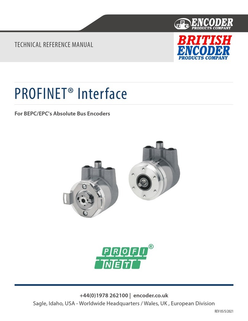
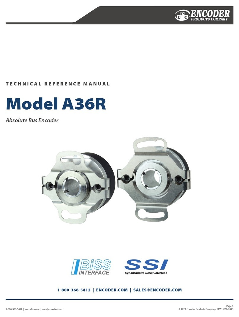
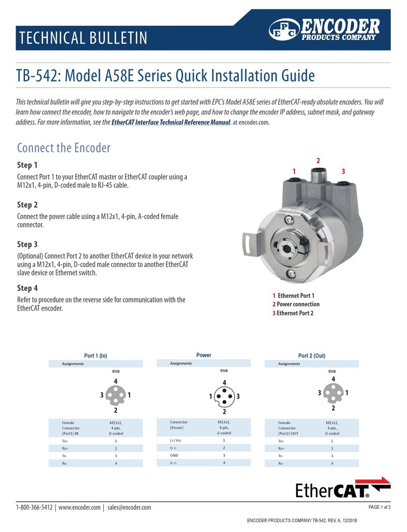
Encoder TB-544 User manual

1-800-366-5412 | www.encoder.com | sales@encoder.com
TECHNICAL BULLETIN
Page 1/10
TB-544 LCX Draw Wire Installation Guide
© 2020 Encoder Products Company TB-544, REV. 11/12/2020
Important Warning Notices
• Do not try to open the device. The stored energy of the spring drive may lead to injuries when being mishandled.
• Do not touch the wire when operating the draw wire unit.
• When mounting outdoors, protect the sensor and the wire from icing up at temperatures below 0° C.The usage of a deection pulley may
help remove ice from the wire.
• When operating the sensor in a humid environment, install the sensor with the wire exit downwards. Otherwise water will gather inside
the housing, which leads to corrosion.Where applicable, use the bottom wire exit option.
READ FIRST! - Proper Handling of the Wire
Unpacking Your Draw Wire Unit
Carefully lift the device out of the box by the housing. Do not pull the wire. After unpacking the device, check it for any visible damage as a
result of rough handling during shipment. Check the package to insure that all parts have been included. If necessary, contact EPC directly for
further assistance.
The wire must be extracted from the draw wire unit in line with the exit axis.
Do not pull on the wire directly.This will buckle the wire. Do not operate the draw wire unit if the wire is buckled or damaged. A damaged or
cut wire may lead to injuries or damage to the draw wire unit and encoder.

1-800-366-5412 | www.encoder.com | sales@encoder.com
Page 2/10
TB-544 LCX DRAW WIRE INSTALLATION GUIDE
© 2020 Encoder Products Company TB-544, REV. 11/12/2020
When installing or operating the draw wire unit, take care not to let the wire snap back accidentally or extract the wire more than the specied
measurement range, as this might destroy the draw wire unit and void the warranty.
Use a deection pulley if required.
Avoid guiding the wire over edges or corners.
The maximum deviation o the exit axis is 3°. Avoid extracting the wire at an angle o the exit axis, since the service life of the draw wire unit
will be greatly reduced. If it is not possible to keep the wire within the specied limit of 3°, a deection pulley must be used.
>3°

1-800-366-5412 | www.encoder.com | sales@encoder.com
Page 3/10
TB-544 LCX DRAW WIRE INSTALLATION GUIDE
© 2020 Encoder Products Company TB-544, REV. 11/12/2020
Handling the Wire
• Route the wire preferably in corners or guarded in channels to prevent contamination or accidental touch.
• Avoid routing the wire over edges or corners. Use a deection pulley instead.
• When installing or operating the draw wire unit, take care not to let the wire snap back accidentally or extract the wire more than the
specied measurement range, as this might damage or destroy the draw wire unit and void the warranty.
• The wire must be extracted from the draw wire unit in line with the exit axis.The maximum deviation o the exit axis is 3°. Avoid extract-
ing the wire at an angle, since the service life of the draw wire unit will shorten considerably. If it is not possible to keep within the limit of
3°, a deection pulley must be used.
• Do not operate the sensor if the wire is buckled or damaged. A cut or loose wire may lead to injuries or a damage to the draw wire unit or
encoder.
Mounting of the Draw Wire Unit
• Please start by mounting the encoder to the LCX draw wire unit. A description is given on the following pages.
• Next mount the draw wire unit at the desired location by using the mounting holes. Do not extract the wire or attach the wire to the
measuring target until the draw wire assembly is securely mounted.
• Depending on the draw wire model it can be installed either by using the holes in the mounting plate or by using the suppliedT-slot nuts/
clamp brackets. You will nd a detailed description of both installation methods in this installation guide.
• Open the wire clip after the draw wire unit is fully mounted and carefully extract the measuring wire. Hook the wire clip on the measuring
target and close the bracket of the clip. For safety, use a screw driver through the clip to extract the wire. Do not pull the wire with your
ngers.
Maintenance
The devices are maintenance-free. If, however, the wire becomes dirty due to adverse environmental conditions, it can be cleaned with a cloth
soaked in resin-free machine oil.

1-800-366-5412 | www.encoder.com | sales@encoder.com
Page 4/10
TB-544 LCX DRAW WIRE INSTALLATION GUIDE
© 2020 Encoder Products Company TB-544, REV. 11/12/2020
Mounting an Encoder
Mounting an Encoder to the LCX80, LCX120, and LCX135 (up to 8 m) draw wire units
The LCX Series draw wire units allow a fast and easy mounting of the encoder by the customer. A detailed description of the mounting
procedure is shown in the following pictures.
IMPORTANT: Encoders suitable for use with the LCX units must have: clamping ange with 36mm diameter; a shaft diameter of 10 mm; and
a shaft length between 10 and 20 mm.
NOTE: All non-metric measurements in this document are for reference only.
Mounting by Clamping Flange
STEP 1
Start by inserting the encoder into the clamping ange.
STEP 2
The encoder is now connected to the clamping ange.

1-800-366-5412 | www.encoder.com | sales@encoder.com
Page 5/10
TB-544 LCX DRAW WIRE INSTALLATION GUIDE
© 2020 Encoder Products Company TB-544, REV. 11/12/2020
STEP 3
By tightening the inner radial screw (approx. 2 Nm / 283 oz-in) with a 2.5 mm hex driver the encoder shaft will be clamped to the draw wire
unit and is secured from slipping.
STEP 4
By tightening the outer radial screw (approx. 2 Nm / 283 oz-in) with a 2.5 mm hex driver the encoder housing will be clamped to the draw wire
housing and is secured from twisting. The complete assembly is now ready to be mounted at the desired location.

1-800-366-5412 | www.encoder.com | sales@encoder.com
Page 6/10
TB-544 LCX DRAW WIRE INSTALLATION GUIDE
© 2020 Encoder Products Company TB-544, REV. 11/12/2020
Mounting an Encoder to LCX135 (10 m and above)
The LCX135 with measurement ranges 10 m or greater is available for an encoder to be mounted by the customer. You will nd a detailed 3
step description of this EASY-Clamp-Mechanism in the next section.
IMPORTANT: All incremental and absolute encoders are suitable that have a clamping ange with 36mm diameter; a shaft diameter of 10 mm;
and a shaft length between 10 and 20 mm.
Easy-Clamp-Mechanism
STEP 1
Start by sliding the included coupling (1) onto the shaft of the encoder and tighten the set screw (1 Nm / 141 oz-in) with a 2 mm hex driver.
Please pay attention that the dimension between contact surface of the encoder and the end of the cylinder bolt is 35 mm.
36
Ø
10
L
= 10...20
36
Ø
(1)
35

1-800-366-5412 | www.encoder.com | sales@encoder.com
Page 7/10
TB-544 LCX DRAW WIRE INSTALLATION GUIDE
© 2020 Encoder Products Company TB-544, REV. 11/12/2020
STEP 2
To mount the encoder into the easy-clamp-ange, slip the cylinder bolt (1) of the coupling into the spring (2).
(1)
(2)

1-800-366-5412 | www.encoder.com | sales@encoder.com
Page 8/10
TB-544 LCX DRAW WIRE INSTALLATION GUIDE
© 2020 Encoder Products Company TB-544, REV. 11/12/2020
STEP 3
Use a 3 mm hex driver to tighten the radial screw (1.5 Nm / 212 oz-in).The encoder will be clamped and secured from twisting.The draw wire
assembly is now ready to be mounted at the desired location.

1-800-366-5412 | www.encoder.com | sales@encoder.com
Page 9/10
TB-544 LCX DRAW WIRE INSTALLATION GUIDE
© 2020 Encoder Products Company TB-544, REV. 11/12/2020
Mounting the LCX80 and the LCX120
Mounting for standard wire exit, sideways top wire exit (option 1)
The draw wire assembly is usually installed by using the regular mounting plate. By disassembling the mounting plate, there are 2 x M4
threads in the draw wire housing for alternative installation.
Mounting for sideways bottom wire exit (option 2), bottom wire exit (option 3)
Draw wire units with option 2 or option 3 wire exits have a modied base plate.
60
17.25
2 x M4
17.25
2 x M4
100
LCX80
LCX80
LCX120
LCX120
Option 2
Option 3
30
9.25
13.8
95
Ø
6.5
19.7
140
Ø
6.5
Option 2
Option 3
13.75
30

1-800-366-5412 | www.encoder.com | sales@encoder.com
Page 10/10
TB-544 LCX DRAW WIRE INSTALLATION GUIDE
© 2020 Encoder Products Company TB-544, REV. 11/12/2020
Mounting the LCX135
Step 1 Mounting via T-slot nuts
The includedT-slot nuts can be easily inserted into the grooves of the sensor housing.The nuts have a M6 thread. Two (up to 20 m
measurement range) or four (more than 25m measurement range) T-slot nuts are included in the package.
Step 2 Mounting via angle clamp brackets
The angle clamp brackets feature a bore for M6 screws to x it on a plate, slab or a prole. Two (up to 20 m measurement range) or four (more
than 25 m measurement range) angle clamp brackets are included in the delivery.
17
7
5.5
10.6
M6
Ø
7
24
27
27
1
2
1515
1515
165
189
Position of the grooves and angle
clamp brackets
Table of contents
Other Encoder Media Converter manuals
Popular Media Converter manuals by other brands
LockTech
LockTech LTKSD 2.0 Set up and operating instructions
Lexicon
Lexicon 5-2-5 Matrix Systems manual
Broadcom
Broadcom AS22 Series Application note
Crestron
Crestron DM-NVX-E10 quick start
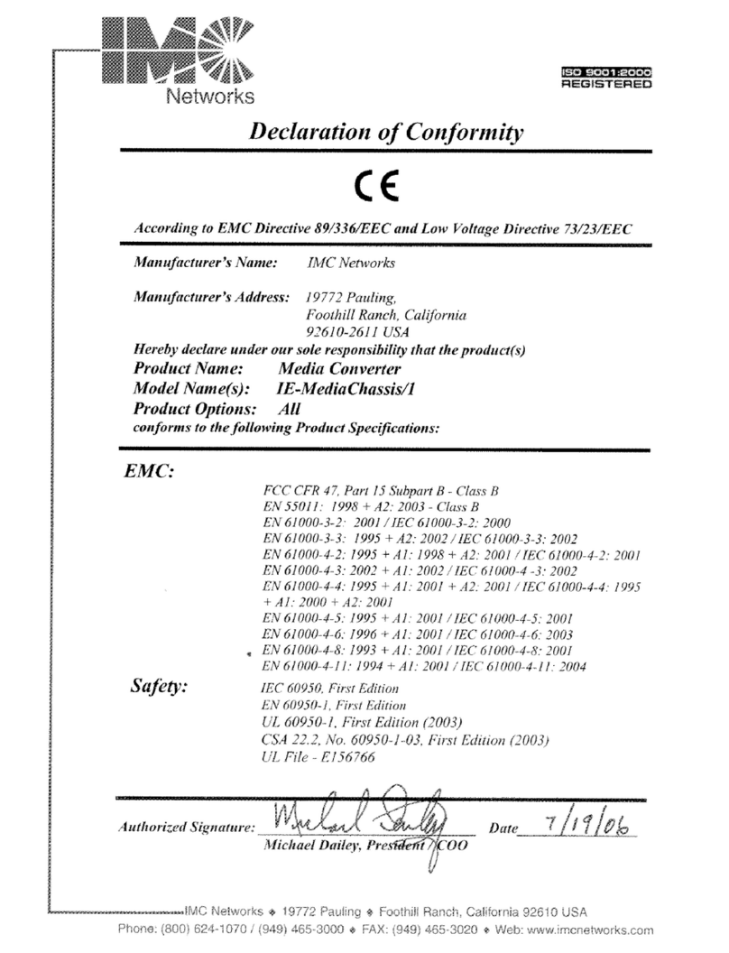
IMC Networks
IMC Networks IE-MediaChassis/1 supplementary guide
horiba
horiba Checker CC-100E operating instructions
