9
Installation Notes for the Cisco TwinGig and OneX Converter Modules
78-17572-04
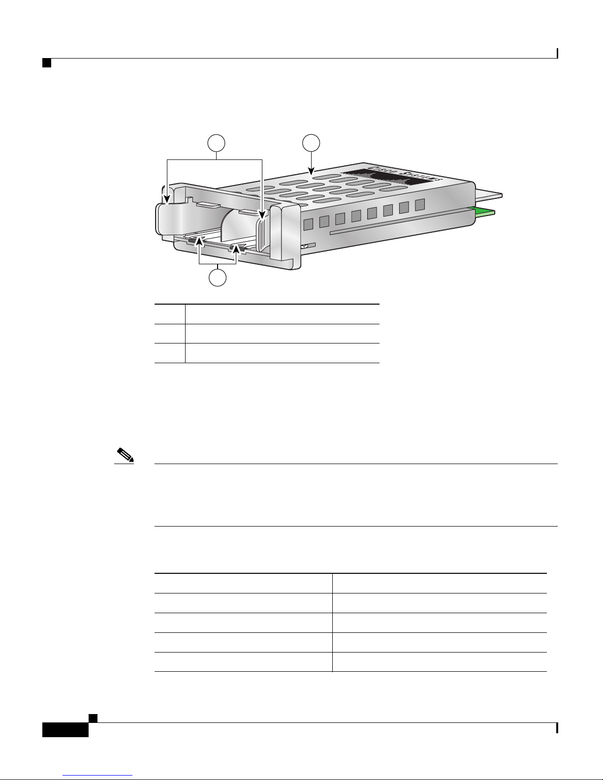
Converter Module Installation
•Do not force the converter module into its slot. This can damage the pins if
they are not aligned with the module.
•Do not remove the EMI plug from the converter module, the dust plug from
the SFP or SFP+ module, or the rubber caps from the fiber-optic cable until
you are ready to connect the cable. The plugs and caps protect the module
ports and cables from contamination and ambient light.
•Removing and installing a module can shorten its useful life. Do not remove
and insert a module more often than is absolutely necessary.
Note Switches support hot swapping of the converter module. You can remove and
replace the module without disconnecting the system power. Hot swapping the
module does not interrupt normal switch operation.
Installing and Removing the Converter Module
These sections describe how to install and remove a Converter Module in a switch
with 10-Gigabit Ethernet module slots.
Note When you install or remove the TwinGig converter module, the mode on the
switch changes from 10 Gigabit Ethernet to Gigabit Ethernet or the reverse.
During this mode change, data traffic on the other switch uplink ports (X2
transceiver or SFP module ports) might temporarily stop. When you install or
remove an X2 transceiver or SFP module, traffic delay does not occur.
Installing a Converter Module
To install a converter module in the switch module slot, follow these steps:
Step 1 Attach an ESD-preventive wrist strap to your wrist and to a bare metal surface.
Step 2 Remove the 10-Gigabit Ethernet module slot EMC plugs and save.