Encoder A58HE Product manual
1-800-366-5412 • encoder.com
Sagle, Idaho
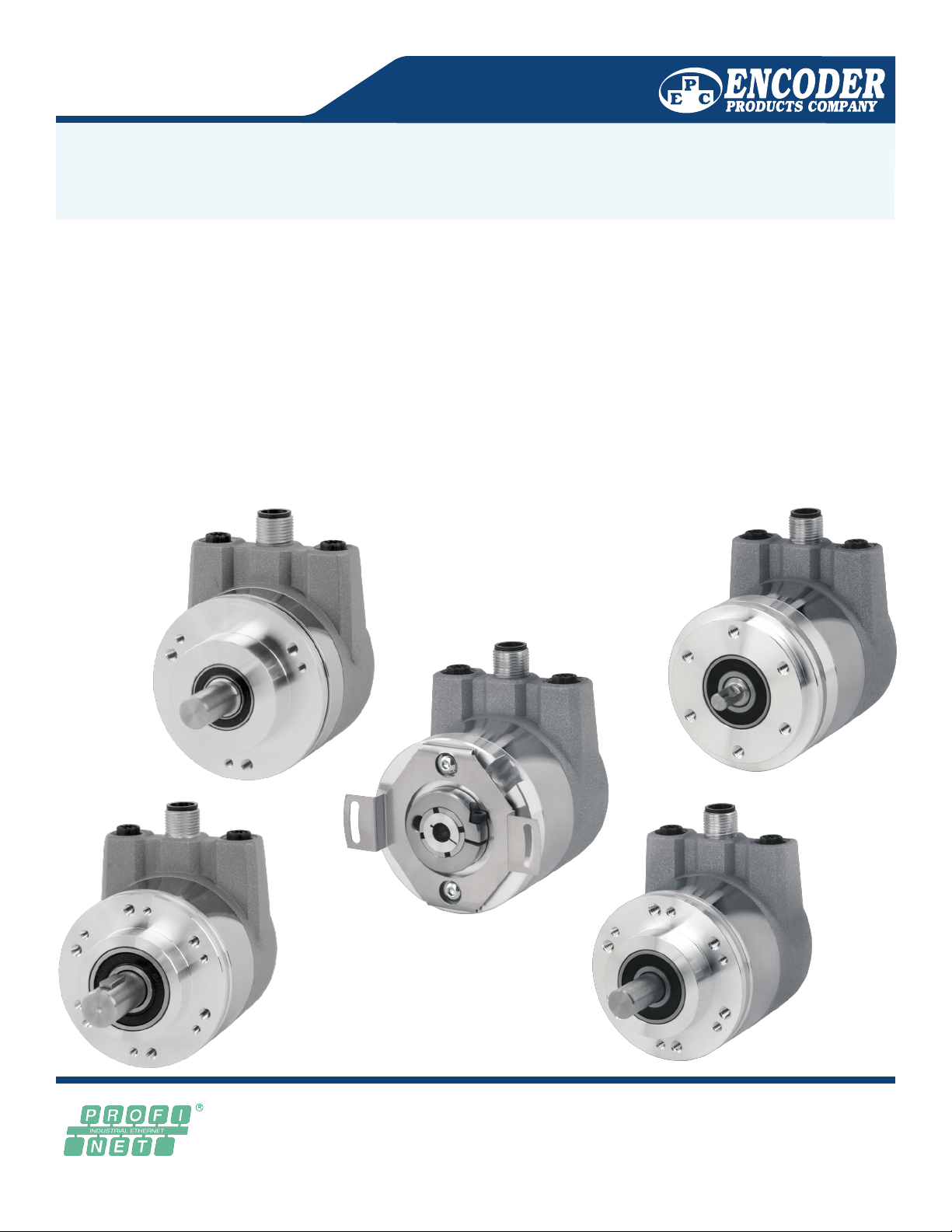
PROFINET Interface
Technical Reference
Manual
for Encoder Products Company
Absolute PROFINET Encoders

PROFINET Interface Technical
Reference Manual
Rev. 10/01/19
©2019 Encoder Products Company. All rights reserved.
464276 Highway 95 South
Encoder Products Company
Sagle, Idaho 83860
USA
Tel: 208 263 8541
Fax: 208 263 0541
E-mail: support-epcmag@encoder.com
Website: encoder.com

PROFINET Interface Technical
Reference Manual
Rev. 10/01/19
1 Introduction ........................................................................ 1
1.1 About This Manual ................................................................................ 1
1.1.1 Explanation of Symbols Used in this Manual ........................... 1
1.1.2 What Is Not in this Manual ...................................................... 2
1.2 Product Supported ................................................................................ 2
1.3 Specifications .......................................................................................2
1.4 Scope of Delivery ................................................................................... 3
2 Safety Information................................................................ 3
2.1 General ....................................................................................... 3
2.2 Intended Use ....................................................................................... 3
2.3 Safe Working .......................................................................................4
2.4 Disposal ....................................................................................... 4
3 Device Description................................................................. 4
3.1 General. .... ............................................................................................4
3.2 PROFINET ...............................................................................................5
3.3 Principles of EPC's A58E Series Encoders ...............................................5
3.3.1 Single Turn – ST ...................................................................... 5
3.3.2 Multi-Turn – MT ...................................................................... 6
3.3.3 Direction of Rotation ............................................................... 6
3.3.4 Preset ...................................................................................... 6
3.3.5 Scaling .................................................................................... 6
3.4 Connection Assignments for PROFINET Encoders ..................................7
3.4.1 Bus Cover with 3 x M12x1 .......................................................7
3.5 LEDs and Signalling ............................................................................... 8
3.6 MAC Address and IP Address .................................................................9
4 . PROFINET .......................................................................10
4.1 Summary of Functions ........................................................................10
4.2 GSDML Modules ..................................................................................10
4.3 Signals ..................................................................................... 11
4.4 Structure of the Signals ....................................................................... 11
4.5 Telegrams .....................................................................................17
4.6 Parameters .....................................................................................18
4.6.1 Description of the Most Important Parameters ..........................19
4.7 Warnings and Errors ............................................................................22
4.7.1 Errors .....................................................................................22
4.7.2 Warning ..................................................................................... 22
4.7.3 G1_XIST2 Error Codes ................................................................ 22
5. Web Server .......................................................................23
5.1 General ..................................................................................... 23
5.2 Information ..................................................................................... 23
5.2.1 Overview ...................................................................................23
5.2.2 Diagnosis ................................................................................... 24
5.2.3 Versions .....................................................................................25
5.3 Configuration .....................................................................................26
5.3.1 Network .....................................................................................26
5.3.2 Encoder .....................................................................................27
5.3.3 Firmware Update ....................................................................... 27
5.4 License information ............................................................................. 30
5.5 Contact .....................................................................................30
6. Commissioning ................................................................................. 31
6.1 General information ............................................................................31
6.2 Integration into a TIA project ............................................................... 31
6.3 Scaling function ..................................................................................41
6.3.1 Example scaling function single turn 16-bit to 12-bit............41
6.3.2 Example scaling function multi-turn .....................................44
6.3.3 Executing a preset .................................................................. 46
6.3.4 Resetting a preset .................................................................. 48
6.4 Integration into a Step 7 project .......................................................... 49
7 . Technical Data ....................................................................55
7.1 Properties .....................................................................................57
7.2 Dimensions .....................................................................................57
8 . Technical support................................................................55
Contents

PROFINET Interface Technical
Reference Manual
Rev. 10/01/19
Figure 3.1: A58HE/SE with PROFINET-IRT Bus Cover............. 4
Figure 5.1: Web server – Overview............................................23
Figure 5.2: Diagnostic Page....................................................... 24
Figure 5.3: Versions ...................................................................25
Figure 5.4: Network Settings...................................................... 26
Figure 5.5: Encoder Information.................................................27
Figure 5.6: Firmware Update .....................................................27
Figure 5.7: Firmware Update – Choose File.............................. 28
Figure 5.8: Firmware Update – Transferring File .......................28
Figure 5.9: Firmware Update – Successful................................29
Figure 5.10: Firmware Update – Failed .....................................29
Figure 5.11: License Information................................................30
Figure 5.12: Contact Information................................................30
Figure 6.1: Switching to Project View.........................................31
Figure 6.2: Manage Device Description File (GSD)...................32
Figure 6.3: Installing GSDML .....................................................33
Figure 6.4: Switch to Devices & Networks................................. 33
Figure 6.5: Hardware Catalogue ................................................34
Figure 6.6: Network View ...........................................................34
Figure 6.7: Change Device Name..............................................34
Figure 6.8: Select Module ..........................................................35
Figure 6.9: Select Telegram ....................................................... 35
Figure 6.10: Change the I/O Addresses.....................................36
Figure 6.11: Download to Device ...............................................36
Figure 6.12: Assigning Device Names .......................................37
Figure 6.13: Name and PG Interface .........................................37
Figure 6.14: Accessible Nodes...................................................38
Figure 6.15: Online Status Information ...................................... 39
Figure 6.16: PLC Variables ........................................................40
Figure 6.17: Show All ................................................................. 40
Figure 6.18: Default Tag Table ...................................................40
Figure 6.19: Example of Commissioning ................................... 41
Figure 6.20: Device Overview – MAP ........................................42
Figure 6.21: Assembly Parameters ............................................42
Figure 6.22: Default Assembly Parameters 16-Bit Single-Turn..43
Figure 6.23: Configuration of 12-Bit Single-Turn with Scaling ... 43
Index of Figures

PROFINET Interface Technical
Reference Manual
Rev. 10/01/19
Index of Figures
Figure 6.24: Example of Commissioning ................................... 44
Figure 6.25: Device Overview – MAP ........................................44
Figure 6.26: Assembly Parameters ............................................45
Figure 6.27: Configuration of 360 Steps/Revolution
and 10 Revolutions ...............................................45
Figure 6.28: Set STW2_ENC Bit 10 to TRUE............................46
Figure 6.29: Set G1_STW Bit 13 to TRUE.................................47
Figure 6.30: G1_STW Bit 11 Default 0 = Absolute.....................47
Figure 6.31: Set and Reset G1_STW Bit 12.............................. 48
Figure 6.32: SIMATIC Manager..................................................49
Figure 6.33: Installing the GSDML File ...................................... 50
Figure 6.34: Hardware Catalogue ..............................................50
Figure 6.35: Hardware View.......................................................51
Figure 6.36: Select Via Single Mouse Click............................... 51
Figure 6.37: Select the Properties and the Telegram.................52
Figure 6.38: Slot 1, Highlighted Green.......................................52
Figure 6.39: Slot 1.2 with Inserted Telegram 81 ........................ 52
Figure 6.40: Change the I/O Addresses.....................................52
Figure 6.41: "Addresses" Tab.....................................................53
Figure 6.42: Save and Transmit – Download to Module............ 53
Figure 6.43: Variable Table......................................................... 53
Figure 6.44: HEX Position Value................................................ 54

PROFINET Interface Technical
Reference Manual
Rev. 10/01/19
Table 3.1: Pin Connection Assignment................................................................................ 7
Table 3.2: LED Signal.......................................................................................................... 8
Table 4.1: Functions ..........................................................................................................10
Table 4.2: GSDML Modules .............................................................................................. 10
Table 4.3: Signals .......................................................................................................... 11
Table 4.4: Structure of Signal 6 NIST_A ........................................................................... 11
Table 4.5: Structure of Signal 8 NIST_B ........................................................................... 12
Table 4.6: Structure of Signal 9 G1_STW......................................................................... 12
Table 4.7: Structure of Signal 10 G1_ZSW....................................................................... 13
Table 4.8: Structure of Signal 11 G1_XIST1 ..................................................................... 13
Table 4.9: Structure of Signal 12 G1_XIST2..................................................................... 14
Table 4.10: Structure of Signal 39 G1_XIST3................................................................... 14
Table 4.11: Structure of Signal 80 STW2_ENC ................................................................ 15
Table 4.12: Structure of Signal 81 ZSW2_ENC ................................................................ 15
Table 4.13: Structure of Signal 238(60000) G1_XIST1_PRESET_A................................ 16
Table 4.14: Structure of Signal 60001 DEBUG_STW....................................................... 16
Table 4.15: Structure of Signal 60002 DEBUG_ZSW....................................................... 16
Table 4.16: Telegrams ....................................................................................................... 17
Table 4.17: Supported Parameters ................................................................................... 18
Table 4.18: Velocity Measuring Units ................................................................................ 20
Table 4.19: Hysteresis Position ......................................................................................... 20
Table 4.20: Extrapolation Position..................................................................................... 21
Table 4.21: Filter Max. RPM.............................................................................................. 21
Table 4.22: Filter Position.................................................................................................. 21
Table 4.23: Filter Speed .................................................................................................... 22
Table 4.24: Errors .......................................................................................................... 22
Table 4.25: Warnings......................................................................................................... 22
Table 4.26: G1_XIST2 Error Codes .................................................................................. 22
Table 6.1: Data Content for Example ................................................................................ 46
Index of Tables
1-800-366-5412 • encoder.com • sales@encoder.com
PROFINET Interface Technical Reference Manual
EPC Technical Reference Manual
Absolute Encoders with PROFINET Interface
REV. 10/01/19
Page 1 of 55
1. Introduction
1.1 About This Manual
This technical manual describes the configuration and mounting possibilities for absolute-value encoders with a PROFINET interface
produced by Encoder Products Company (EPC). It supplements the other publicly available EPC documents, e.g. data sheets,
assembly instructions, leaflets, catalogues and flyers.
Ensure that you read the manual before provisioning — check beforehand that you have the latest version of the manual.
When reading, pay particular attention to the information, important notices and warnings that are marked with the corresponding
symbols (see 1.1.1).
This manual is intended for persons with technical knowledge in the handling of sensors, PROFINET IRT interfaces and automation
elements. If you do not have any experience in this field, request the assistance of experienced personnel before proceeding.
Keep the information provided with our product in a safe place so that you can refer to it at a later date as necessary.
The contents of this manual are arranged with practical use in mind.•
All of the information in the following sections is required to get the best possible use out of the•
equipment, and should be read through thoroughly.
1.1.1 Explanation of Symbols Used in this Manual
The IMPORTANT symbol is placed next to a section of text in which a process is
described to resolve a particular problem.
The INFO symbol is placed next to a section of text that is particularly informative or
important for what to do next with the equipment.
The WARNING symbol is placed next to a section of text that should be paid particular
attention to in order to ensure the correct use of the equipment and to protect against
danger.

1-800-366-5412 • encoder.com • sales@encoder.com
PROFINET Interface Technical Reference Manual
EPC Technical Reference Manual
Absolute Encoders with PROFINET Interface
REV. 10/01/19
Page 2 of 55
1.1.2 What Is Not in this Manual
Basic information about automation technology•
System planning•
Risks (availability, safety)•
Shielding concepts•
Reections•
Repeaters•
Networkconguration•
Bus cycle times•
FMA management services•
Transmission services•
Telegram types•
1.2 Products Supported
This manual supports the following types of EPC Absolute Encoders:
Model A58HE – PROFINET absolute hollow-bore encoder with bus cover
ModelA58SE–PROFINETabsoluteshaftencoder,synchroorclampingange,heavy-dutyorcompact,withbuscover
1.3 Specications
An encoder is a sensor that is designed to detect angular positions (single-turn) and revolutions (multi-turn). The measured data and
variables are processed by the encoder and provided as electrical output signals for the connected peripherals.
Patented technologies for single-turn and for multi-turn are used in the A58SE and A58HE series encoders. As a result, these
encoders from EPC are maintenance-free and very eco-friendly.
The encoders whose article descriptions are listed in Section 1.2 communicate via the PROFINET IRT interface.
EPC’s PROFINET product range can be found on our website: encoder.com
1-800-366-5412 • encoder.com • sales@encoder.com
PROFINET Interface Technical Reference Manual
EPC Technical Reference Manual
Absolute Encoders with PROFINET Interface
REV. 10/01/19
Page 3 of 55
1.4 Scope of Delivery
The scope of delivery depends on the product variants and the details of your order. Before commissioning, check the
contents of the delivery for completeness.
As a rule, the A58HE and A58SE products have a PROFINET IRT interface includes the following items:
• A58HEorA58SEwithPROFINET-IRT(withbuscover)
• Assemblyinstructions
2 Safety Information
2.1 General
2.2 Intended Use
Rotary encoders are components that are intended for installation in machines. Before commissioning (operation in
accordance with the intended use), it must be determined that the machine as a whole corresponds to the EMC and
Machine Directive.
A rotary encoder is a sensor that is designed to detect angular positions and revolutions and must only be used for this
purpose! EPC Automation manufactures and distributes encoders for use in non-safety-relevant industrial applications.
When provisioning the encoder, ensure that you observe the•
assembly instructions, manual and data sheet.
Failure to observe the safety instructions may lead to malfunctions,•
property damage and personal injury!
Observe the operating instructions provided by the machine's•
manufacturer.
ThecorrespondingGSDMLleanddatasheetcanbedownloadedatencoder.com.
Theencodermustnotbeoperatedoutsidethespeciedlimitparameters
(see product datasheet).
1-800-366-5412 • encoder.com • sales@encoder.com
PROFINET Interface Technical Reference Manual
EPC Technical Reference Manual
Absolute Encoders with PROFINET Interface
REV. 10/01/19
Page 4 of 55
2.3 Safe Working
Theinstallationandmountingoftheencodermustonlybecarriedoutbyaqualiedelectrician.
For the construction of electrical installations, all relevant national and international regulations must be strictly observed.
Failure to commission the encoder correctly may result in malfunction or failure.
2.4 Disposal
Devicesthatarenolongerneededoraredefectivemustbedisposedbytheuserinpropercompliancewiththecountry-speciclaws.
It must be taken into consideration that this is a special waste of electronics and that disposal is not permitted via normal household
waste.
There is no obligation by the manufacturer to take the device back. If you have any questions regarding proper disposal, contact a
disposal specialist in your area.
3 Device Description
3.1 General
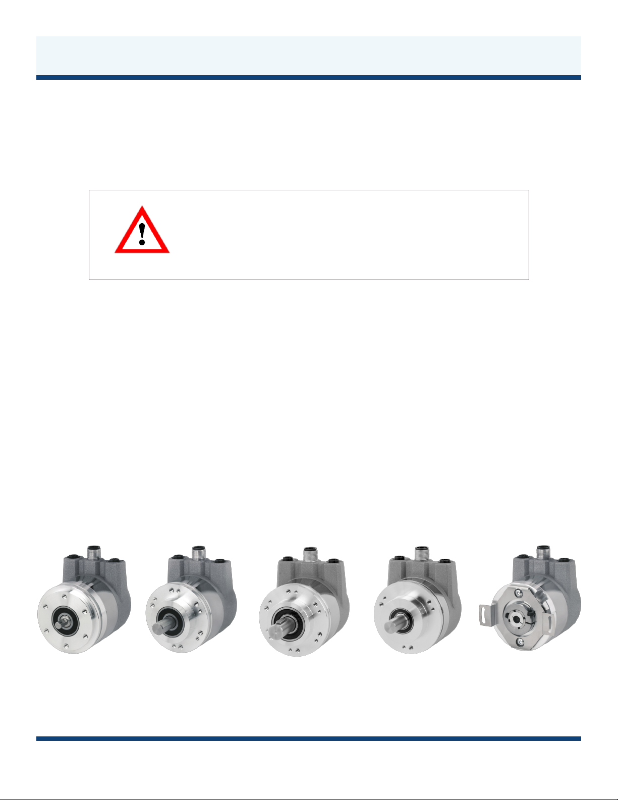
Various mechanical variants of the A58SE and A58HE-series encoders with PROFINET-IRT are available. The required variant is
determinedbytheneedforabuscover,theangedesignandtheshafttype(solidorhollow).Thesizeisspeciedas58mmbythe
diameterattheange.ThefollowinggureshowsexamplesofA58SE/HE-seriesencoderswithPROFINETIRT.
Figure 3.1: EPC EtherCAT-Ready Encoders with PROFINET-IRT Bus Covers
From left to right: A58SE with clamping ange; A58SE with synchro ange; A58SE heavy-duty; A58SE compact; A58HE (blind hollow bore)
All electrical connections must be tested before commissioning.•
Appropriate safety measures must be taken to ensure that no persons•
are harmed and no damage to the system or operating equipment
occurs in the event of a failure or malfunction.

1-800-366-5412 • encoder.com • sales@encoder.com
PROFINET Interface Technical Reference Manual
EPC Technical Reference Manual
Absolute Encoders with PROFINET Interface
REV. 10/01/19
Page 5 of 55
The solid or hollow shaft is connected to the rotating component whose angular position or rotational speed is to be measured.
Cable or plug outlets create the interface for connection to the PROFINET network. The status LEDs mounted in the cover signal the
variousencoderstatesduringoperation.Theyassistwithcongurationoftheencoderandtroubleshootingintheeld.Theange
holes or supplied spring sheets are used for attachment to the machine and during the respective application.
3.2 PROFINET
PROFINETisdistributedbythePROFIBUSUserOrganization(PNO)asasuccessortoProbus.PROFINETisthestandard
interfaceforindustrialEthernet.PROFINETprovidessimilarfunctionalitytoProbus,butextendsthesebyrmwareupgrades.
Established IT standards are used for the transfer of information. UDP, IP and XML form the basis for this. XML is used as a
description language
inthedeviceprole(abbreviatedto"GSDMLle").InorderforthedevicestoexchangetheirdataviaIP—processdata(cyclic)and
parameterdata(acyclic)—auniquenamemustbeassignedtoeachPROFINETnodeduringconguration.Thecontrolcanonly
assign an IP address to the node via this name.
PROFINET supports the following three transmission types:
PROFINET NRT• (not real time), non-time-critical applications in automation, clock rates of around 100 milliseconds.
PROFINET RT• (realtime),cyclicdatatrafcisusedtoachieveclockratesof10milliseconds.
PROFINET IRT• (isochronous real time), clock rates of 1 millisecond and jitter of less than 1 microsecond. This is suitable for use
in motion-control applications (for example).
FurtherinformationaboutPROFINETisavailableviathehomepageofthePROFIBUSUserOrganization(PNO)at:
http://www.probus.com/technology/PROFINET/
3.3 Principles of EPC'S A58E Series Encoders
The following sections describe the basic functions of an absolute encoder.
Unlikeincrementalencoders,absolute-valueencodersoutputtheirpositionvalueasadigitalnumberviaaeldbus.Adistinctionis
made here between single-turn and multi-turn encoders.
Inadditiontosimplyoutputtingthepositionvalue,mostencoderspermitacertaindegreeofparameterization,suchasselectingthe
positivedirectionofrotation,settingthepositionvaluetoareferencevalueataxedphysicalposition,andscalingthepositionvalue
to an arbitrary resolution and a limited measuring range. This reduces the required complexity of the control program as well as the
computational burden on the controller.
3.3.1 Single Turn – ST
Measurement of the angle from 0° to 360° by means of a shaft represents the minimum functionality of a rotary encoder.
The sensor system is based on optical or magnetic sampling of a measuring graduation on the encoder shaft.
The A58SE/HE encoders from EPC feature new magnetic technology, which provides maximum precision and resolution for
a single-turn encoder.

1-800-366-5412 • encoder.com • sales@encoder.com
PROFINET Interface Technical Reference Manual
EPC Technical Reference Manual
Absolute Encoders with PROFINET Interface
REV. 10/01/19
Page 6 of 55
3.3.2 Multi-Turn – MT
A multi-turn encoder allows the number of revolutions to be recorded. This is achieved via a rotation counter. The A58SE
and A58HE encoders include technology, which ensures that the corresponding information is retained, even in a voltage-
free state. This means that buffer batteries and gearboxes, which require a comparatively large installation space and a
correspondingly high degree of maintenance, are no longer needed.
3.3.3 Direction of Rotation
The positive direction of rotation can be reversed by a simple two's complement of the position value (invert every bit and
add "1").
3.3.4 Preset
Thedesiredpositionvaluecanbeassignedtotheencoderataspecicphysicalposition.Thismustbewithinthemeasuring
range so that the position value is correlated with a physical reference position. For this purpose, the difference between
the current position value and the desired value is calculated. The result is stored in non-volatile memory and added to the
position value as an offset.
3.3.5 Scaling
For the precise matching of the position value with the parameter to be measured in physical terms, adjustments can be
carried out using the scaling parameters. The scalable parameters are "Measuring units per revolution (MUPR)" and "Total
measuring range in measuring units (TMR)".
The scaling parameters "Measuring units per revolution (MUPR)" – increments per revolution – indicates the resolution of
the position value per revolution (also: ST resolution). The value equates to 360°. This means that, if a value of 3600 Cts is
parametrized,theencoderoutputsthepositionin0.1°increments(seeEquation#2).
Equation#1 MUPR = ST = 3600 Cts
Equation#2
The scaling parameter "Total measuring range in measuring units (TMR)" – the maximum total measuring range of the position value
(single-turn and multi-turn multiplied) – indicates the total resolution of the encoder. When the position value reaches TMR -1, it
jumps back to 0 and vice versa.
As a rule, the selected TMR parameter should be an integer multiple of the "Measuring units per revolution (MUPR)" (see equation
#4),sothatthezeropointisalwaysatthesamepositionoftheencodershaft.
Equation#3 TMR = 36000 Cts
Equation#4
MUPR
Angle of one revolution
Angular steps = = 0.1°/ Cts
=36000 Cts
360°
MUPR
TMR
MT = = 10
=3600 Cts
36000 Cts

1-800-366-5412 • encoder.com • sales@encoder.com
PROFINET Interface Technical Reference Manual
EPC Technical Reference Manual
Absolute Encoders with PROFINET Interface
REV. 10/01/19
Page 7 of 55
In exceptional cases, it is suitable that TMR is not an integer multiple of MUPR – for example, in a system in which a gear ratio
ensures that the desired measured variable is moving 10% faster relative to the encoder shaft.
In this case, a setting of MUPR = 3960 Cts and TMR = 36000 Cts would ensure that the faster (but not directly measurable) shaft can
be measured with a resolution of 0.1° and over a range of 10 revolutions. Normally, the number of revolutions would be calculated by
dividing the position value by MUPR. In this case, however, it must be divided by 3600 Cts, since the result would otherwise be the
number of revolutions of the encoder shaft and not the faster shaft of the system.
3.4 Connection Assignments for PROFINET Encoders
3.4.1 Bus Cover with 3 x M12x1
The "RNB" code in the order key refers to an encoder with a bus cover. The electrical connection is made at the
bus cover via the 2 x M12 plugs and 1 x M12 socket. The connection assignment of the plugs and sockets can be
found in Table 3.1.
Table 3.1: Pin Connection Assignment
It should be noted that measurement errors occur if the result of this formula is a
decimal.
Port 1 (In)
Assignments
RNB
Female
Connector
(Port1) IN
M12x1,
4-pin,
D-coded
Tx+ 1
Rx+ 2
Tx- 3
Rx- 4
Power
Assignments
RNB
Connector
(Power)
M12x1,
4-pin,
A-coded
(+) Vcc 1
n. c. 2
GND 3
n. c. 4
Port 2 (Out)
Assignments
RNB
Female
Connector
(Port2) OUT
M12x1,
4-pin,
D-coded
Tx+ 1
Rx+ 2
Tx- 3
Rx- 4
Tx+ 1
Rx+ 2
Tx- 3
Rx- 4
Female Connector
Port1 (IN)
M12x1,
4-pin,
D-coded
Function
(+) Vcc 1
n. c. 2
GND 3
n. c. 4
Power
M12x1,
4-pin,
A-coded
Function
Tx+ 1
Rx+ 2
Tx- 3
Rx- 4
Female Connector
Port2 (OUT)
M12x1,
4-pin,
D-coded
Function
Below is version from Daniel Konoff. Above version contains
same information, approved format from Cody Swisher and
Sarah Walter 9/19/19

1-800-366-5412 • encoder.com • sales@encoder.com
PROFINET Interface Technical Reference Manual
EPC Technical Reference Manual
Absolute Encoders with PROFINET Interface
REV. 10/01/19
Page 8 of 55
3.5 LEDs and Signalling
FourstatusLEDsonthebuscoversignalthevariousencoderstatesandthussupporterrordiagnosisandtroubleshootingintheeld
(seeTable3.2).ThetwoLinkActivityLEDs(L/A)lightuporashgreenwhentheencoderisconnectedtoanotherPROFINETnode
(PLC,switch,additionalelddevice...)anddataisbeingexchanged.TheSTATLEDindicatesthestatusoftheeldbus,theMOD
LED the status of the encoder.
STAT LED
dual color
MOD LED
dual color Meaning Cause
No voltage
No connection;
no data exchange
Bus disconnection or master not
accessible or switched off
Parametrizationerror,nodataexchange
Criterion:
Data exchange correct.
However, the slave does not switch to the
data-exchange mode
Slaveisnotconguredyet.
Incorrect station address, but not out of
range.
Theactualcongurationoftheslave
differsfromthenominalconguration.
System error Diagnosis exists,
slave is in data-exchange mode
Data exchange,
slave and operation OK
Table 3.2 LED signal
Explanation of symbols and asterisks:
LEDoff/LEDonLEDashing

1-800-366-5412 • encoder.com • sales@encoder.com
PROFINET Interface Technical Reference Manual
EPC Technical Reference Manual
Absolute Encoders with PROFINET Interface
REV. 10/01/19
Page 9 of 55
3.6 MAC Address and IP Address
EPC PROFINET encoders have three MAC addresses. These always start with D4-90-E0-xx-xx-xx. The number depends on the
number of ports on the integrated three-port switch. There is one MAC address each for Port1 and Port2, as well as one MAC
address for the "internal port" to which the encoder itself is connected.
Inthedeliveredstate,thePROFINETencoderhasnoIPaddressandnoname.Thesearedenedduringconguration(e.g.,TIA
Portal).

1-800-366-5412 • encoder.com • sales@encoder.com
PROFINET Interface Technical Reference Manual
EPC Technical Reference Manual
Absolute Encoders with PROFINET Interface
REV. 10/01/19
Page 10 of 55
4 PROFINET
4.1 Summary of Functions
Our PROFINET encoders support the functions shown in Table 4.1, below.
Functions Meaning
Conformance class CC-C
Prole EncoderProleV4.1
Proleclass EncoderProleClass4,
as well as compatibility with Class 3
Performance Cycletime250μs(withclocksynchronisation)and
fast start-up of 1 s
Redundancy MPR and MRPD
Web server Displayandcongurationofparameters,
rmwareupdates
Clock synchronisation RT, IRT and IRT isochronous
Table 4.1: Functions
4.2 GSDML Modules
ThemodulesfromthecurrentGSDMLlearelistedinTable4.2,below
Designation Meaning
ST0013 No multi-turn, single-turn 13 bit
ST0016 No multi-turn, single-turn 16 bit
MT1413 Multi-turn 14 bit + single-turn 13 bit = 27 bits in total
MT1416 Multi-turn 14 bit + single-turn 16 bit = 30 bits in total
MT1616 Multi-turn 16 bit + single-turn 16 bit = 32 bits in total
MT3916 Multi-turn 39 bit + single-turn 16 bit = 55 bits in total
Table 4.2: GSDML Modules

1-800-366-5412 • encoder.com • sales@encoder.com
PROFINET Interface Technical Reference Manual
EPC Technical Reference Manual
Absolute Encoders with PROFINET Interface
REV. 10/01/19
Page 11 of 55
Signal Description Name Length (bits) Signed
6 Velocity A NIST_A 16 Y
8 Velocity B NIST_B 32 Y
9 Sensor 1 control word G1_STW 16 –
10 Sensor 1 status word G1_ZSW 16 –
11 Sensor 1 position 1 G1_XIST1 32 N
12 Sensor 1 position 2 G1_XIST2 32 N
39 Sensor 1 position 3 G1_XIST3 64 N
80 Encoder control word 2 STW2_ENC 16 –
81 Encoder status word 2 ZSW2_ENC 16 –
238
(60000)
Sensor position preset
control word G1_XIST_PRESET_A 32 N
60001 Debug control word DEBUG_STW 16 N
60002 Debug status word DEBUG_ZSW 16 N
Table 4.3: Signals
4.3 Signals
Table 4.3, below, shows the signals that are supported by EPC PROFINET encoders.
4.4 Structure of the signals
NIST_A: Velocity value A
This value includes the velocity, has a width of 16 bits and is signed.
Signal NIST_A
Bits 15 ... 0
Contents
15 … 0 Velocity value A Right-aligned, output in set unit
(see Table 4.18, Velocity Measuring Units)
Table 4.4: Structure of signal 6 NIST_A

1-800-366-5412 • encoder.com • sales@encoder.com
PROFINET Interface Technical Reference Manual
EPC Technical Reference Manual
Absolute Encoders with PROFINET Interface
REV. 10/01/19
Page 12 of 55
Signal NIST_B
Bits 31 ... 0
Contents
31 … 0 Velocity value B Right-aligned, output in set unit
(see Table 4.18, Velocity Measuring Units)
Table 4.5: Structure of signal 8 NIST_B
NIST_B: Velocity value B
This value includes the velocity, has a width of 32 bits and is signed.
G1_STW: Sensor 1 control word
Signal G1_STW
Bit 15 14 13 12 11 10 ... 0
Contents
15 Conrmsensorerror 0=Sensorerrornotconrmedbycontroller
1=Sensorerrorconrmedbycontroller
14 Park mode 0 = Normal operation
1 = Activate park mode
13 Cyclically query absolute position value
0 = Do not interrogate
1 = Master performs query (cyclic output of
G1_XIST2)
12 Activate preset 0 = Preset not active
1 = Preset active
11 Preset mode 0 = Set preset to absolute value
1 = Move preset by value (offset)
10 ... 0 Reserved, currently not used
Table 4.6: Structure of signal 9 G1_STW
To enable the encoder to respond to the requirements in G1_STW, the controller
must set bit 10 to 1 in STW2_ENC.

1-800-366-5412 • encoder.com • sales@encoder.com
PROFINET Interface Technical Reference Manual
EPC Technical Reference Manual
Absolute Encoders with PROFINET Interface
REV. 10/01/19
Page 13 of 55
G1_ZSW: Sensor 1 status word
Signal G1_ZSW
Bit 15 14 13 12 11 10 ... 0
Contents
15 Sensor error Signals a sensor error and outputs a device-
specicerrorcodeinG1_XIST2
14 Park mode active Conrms"Parkmode".Noerrormessages
are transmitted
13 Cyclically query absolute position value Conrms"cyclicallyqueryabsoluteposition
value"
12 Preset activated Conrms"activatepreset"
11 Sensor error acknowledgement active Signals processing of the requested sensor
error acknowledgement
10 ... 0 Reserved, currently not used
Table 4.7: Structure of signal 10 G1_ZSW
G1_XIST1: Sensor 1 position 1
Signal G1_XIST1
Bits 31 ... 0
Contents
31 ... 0 Absolute position value 1 Right-aligned
Table 4.8: Structure of signal 11 G1_XIST1
Structure of G1_XIST1 using the example of a 16-bit multi-turn and a 16-bit single-turn encoder:
31 30 29 28 27 26 25 24 23 22 21 20 19 18 17 16
MMMMMMMMMMMMMMMM
15 14 13 12 11 10 9 8 7 6 5 4 3 2 1 0
SSSSSSSSSSSSSSSS
M = multi-turn / S = single turn
Thisvalueincludestheposition,hasawidthof32bits,andisunsigned.Theencoderparametersettingsinuence
thispositionvalueif"Class4functionality"isactivated.Theinuenceofthepresetfunctionalitycanbecontrolledwith
"G1_XIST1 Preset Control".
1-800-366-5412 • encoder.com • sales@encoder.com
PROFINET Interface Technical Reference Manual
EPC Technical Reference Manual
Absolute Encoders with PROFINET Interface
REV. 10/01/19
Page 14 of 55
G1_XIST2: Sensor 1 position 2
Signal G1_XIST2
Bits 31 ... 0
Contents
31 ... 0 Absolute position value 2 Right-aligned
Table 4.9: Structure of signal 12 G1_XIST2
Thisvalueincludestheposition,hasawidthof32bitsandisunsigned.Theencoderparametersettingsinuencethis
positionvalueif"Class4functionality”isactivated.Whenactivated,thepresetfunctionalityalwayshasaninuenceon
G1_XIST2.
If an error occurs, G1_XIST2 contains the error register instead of the position value.
G1_XIST3: Sensor 1 position 3
Signal G1_XIST3
Bits 63 ... 0
Contents
63 ... 0 Absolute position value 3 Right-aligned
Table 4.10: Structure of signal 39 G1_XIST3
This value includes the position, has a width of 64 bits and is unsigned.
Itcanbeusedifthemeasuringrangeoftheencoderislargerthan32bits.Theencoderparametersettingsinuencethis
position value if "Class 4 functionality" is activated.
This manual suits for next models
1
Table of contents
Other Encoder Media Converter manuals


