Encoder A36R Product manual

TECHNICAL REFERENCE MANUAL
Model A36R
Absolute Bus Encoder
1-800-366-5412 | encoder.com | sales@encoder.com
Page 1
© 2023 Encoder Products Company, REV 11/08/2023
1-800-366-5412 | ENCODER.COM | SALES@ENCODER.COM

PAGE 2 OF 331-800-366-5412 | encoder.com | sales@encoder.com
EPC Technical Reference Manual – Model A36R
© 2023 Encoder Products Company, REV 11/08/2023
TECHNICAL REFERENCE MANUALModel A36R
©2023 Encoder Products Company. All rights reserved.
Encoder Products Company
464276 Highway 95 South
Sagle, Idaho 83860
USA
Phone: (208) 263-8541
Fax: (208) 263-0541
Email (USA): support@encoder.com
Email (other countries): sales@encoder.com
Website: encoder.com

PAGE 3 OF 331-800-366-5412 | encoder.com | sales@encoder.com
EPC Technical Reference Manual – Model A36R
© 2023 Encoder Products Company, REV 11/08/2023
TECHNICAL REFERENCE MANUALModel A36R
1. Introduction . . . . . . . . . . . . . . . . . . . . . . . . . . . . . . . . . . . . . . . . . . . . . 6
1.1 Encoder Types . . . . . . . . . . . . . . . . . . . . . . . . . . . . . . . . . . . . . . . . . . . .6
1.2 About This Manual . . . . . . . . . . . . . . . . . . . . . . . . . . . . . . . . . . . . . . . . .6
1.3 Explanation of Symbols . . . . . . . . . . . . . . . . . . . . . . . . . . . . . . . . . . . . . .7
2. Safety Information . . . . . . . . . . . . . . . . . . . . . . . . . . . . . . . . . . . . . . . . . 7
2.1 Work Safely . . . . . . . . . . . . . . . . . . . . . . . . . . . . . . . . . . . . . . . . . . . . . .7
2.2 Special Handling & Disposal . . . . . . . . . . . . . . . . . . . . . . . . . . . . . . . . . . .7
3. Quick Start Guide . . . . . . . . . . . . . . . . . . . . . . . . . . . . . . . . . . . . . . . . . . 8
3.1 Cabling Considerations . . . . . . . . . . . . . . . . . . . . . . . . . . . . . . . . . . . . . .8
4. A36R Conguration Options . . . . . . . . . . . . . . . . . . . . . . . . . . . . . . . . . . . 8
4.1 Multi-Turn Options . . . . . . . . . . . . . . . . . . . . . . . . . . . . . . . . . . . . . . . . .8
4.2 Low Power Circuit (XXL) Operation . . . . . . . . . . . . . . . . . . . . . . . . . . . . . . .8
4.3 Multi-Turn Cable Options for XXL Version . . . . . . . . . . . . . . . . . . . . . . . . . . 10
4.3.1 Low Power Option (XXL) with Embedded Battery Cable (EB). . . . . . . . . . . . . . . 11
4.3.2 Low Power Option (XXL) with Power Ready Cable (no EB option) . . . . . . . . . . . . 11
5. Backup Power Installation and Replacement . . . . . . . . . . . . . . . . . . . . . . . . 12
5.1 Backup Power Installation. . . . . . . . . . . . . . . . . . . . . . . . . . . . . . . . . . . . 12
5.2 Backup Power Replacement . . . . . . . . . . . . . . . . . . . . . . . . . . . . . . . . . . 13
6. Features . . . . . . . . . . . . . . . . . . . . . . . . . . . . . . . . . . . . . . . . . . . . . . . 13
6.1 Preset Pin . . . . . . . . . . . . . . . . . . . . . . . . . . . . . . . . . . . . . . . . . . . . . . 13
6.2 Error and Warning Monitoring . . . . . . . . . . . . . . . . . . . . . . . . . . . . . . . . . 14
7. SSI Protocol . . . . . . . . . . . . . . . . . . . . . . . . . . . . . . . . . . . . . . . . . . . . . 16
7.1 Overview . . . . . . . . . . . . . . . . . . . . . . . . . . . . . . . . . . . . . . . . . . . . . . 16
7.2 SSI Packet Structure. . . . . . . . . . . . . . . . . . . . . . . . . . . . . . . . . . . . . . . . 17
7.3 SSI Communication Timing . . . . . . . . . . . . . . . . . . . . . . . . . . . . . . . . . . . 18
7.4 Cable Length vs. Frequency . . . . . . . . . . . . . . . . . . . . . . . . . . . . . . . . . . . 19
8. BiSS C Protocol . . . . . . . . . . . . . . . . . . . . . . . . . . . . . . . . . . . . . . . . . . . 19
8.1 Overview . . . . . . . . . . . . . . . . . . . . . . . . . . . . . . . . . . . . . . . . . . . . . . 19
8.2 BiSS C Packet Structure. . . . . . . . . . . . . . . . . . . . . . . . . . . . . . . . . . . . . . 20
8.3 BiSS C Communication Timing . . . . . . . . . . . . . . . . . . . . . . . . . . . . . . . . . 20
8.4 Cable Length vs. Frequency . . . . . . . . . . . . . . . . . . . . . . . . . . . . . . . . . . . 21
8.5 A36R BiSS Register Mapping . . . . . . . . . . . . . . . . . . . . . . . . . . . . . . . . . . 22
8.5.1 A36R General Memory Map . . . . . . . . . . . . . . . . . . . . . . . . . . . . . . . . . . . 22
8.5.2 BiSS EDS – Common Part. . . . . . . . . . . . . . . . . . . . . . . . . . . . . . . . . . . . . 23
8.5.3 BiSS EDS – BP3: BiSS Standard Encoder Prole . . . . . . . . . . . . . . . . . . . . . . . 25
8.5.4 Read and Write Registers. . . . . . . . . . . . . . . . . . . . . . . . . . . . . . . . . . . . . 27
8.6 BiSS Commands . . . . . . . . . . . . . . . . . . . . . . . . . . . . . . . . . . . . . . . . . . 28
8.6.1 PRESET Command . . . . . . . . . . . . . . . . . . . . . . . . . . . . . . . . . . . . . . . . . 29
8.6.2 MEASURE Command . . . . . . . . . . . . . . . . . . . . . . . . . . . . . . . . . . . . . . . 29
8.6.3 DIAG Command . . . . . . . . . . . . . . . . . . . . . . . . . . . . . . . . . . . . . . . . . . 29
8.6.4 TEMP_LIMIT_SET Command. . . . . . . . . . . . . . . . . . . . . . . . . . . . . . . . . . . 29
9. CRC Details . . . . . . . . . . . . . . . . . . . . . . . . . . . . . . . . . . . . . . . . . . . . . 29
10. Model A36R Datasheet . . . . . . . . . . . . . . . . . . . . . . . . . . . . . . . . . . . . . 30
Table of Contents

PAGE 4 OF 331-800-366-5412 | encoder.com | sales@encoder.com
EPC Technical Reference Manual – Model A36R
© 2023 Encoder Products Company, REV 11/08/2023
TECHNICAL REFERENCE MANUALModel A36R
Figure 1: Battery current draw vs. shaft speed in Active state . . . . . . . . . . . . . . . . . . . . . . . . 10
Figure 2: XXL option cable congurations. . . . . . . . . . . . . . . . . . . . . . . . . . . . . . . . . . . . . 11
Figure 3: SSI data stream with nERR and nWARN for condition reporting . . . . . . . . . . . . . . . . 14
Figure 4: BiSS data stream with nERR and nWARN for condition reporting . . . . . . . . . . . . . . . 14
Figure 5: Typical SSI point-to-point connections . . . . . . . . . . . . . . . . . . . . . . . . . . . . . . . . 17
Figure 6: SSI data exchange. . . . . . . . . . . . . . . . . . . . . . . . . . . . . . . . . . . . . . . . . . . . . . 17
Figure 7: SSI timing diagram . . . . . . . . . . . . . . . . . . . . . . . . . . . . . . . . . . . . . . . . . . . . . 18
Figure 8: BiSS data exchange. . . . . . . . . . . . . . . . . . . . . . . . . . . . . . . . . . . . . . . . . . . . . 20
Figure 9: BiSS timing diagram . . . . . . . . . . . . . . . . . . . . . . . . . . . . . . . . . . . . . . . . . . . . 21
Index of Figures

PAGE 5 OF 331-800-366-5412 | encoder.com | sales@encoder.com
EPC Technical Reference Manual – Model A36R
© 2023 Encoder Products Company, REV 11/08/2023
TECHNICAL REFERENCE MANUALModel A36R
Table 1: Battery monitor warning/error thresholds. . . . . . . . . . . . . . . . . . . . . . . . . . . . . . . . 9
Table 2: Model A36R use cases for embedded battery cable . . . . . . . . . . . . . . . . . . . . . . . . . . 9
Table 3: Battery specications for EB cable . . . . . . . . . . . . . . . . . . . . . . . . . . . . . . . . . . . . 11
Table 4: Voltage requirements for backup power interface. . . . . . . . . . . . . . . . . . . . . . . . . . 12
Table 5: Model A36R error log . . . . . . . . . . . . . . . . . . . . . . . . . . . . . . . . . . . . . . . . . . . . 15
Table 6: Model A36R warning log . . . . . . . . . . . . . . . . . . . . . . . . . . . . . . . . . . . . . . . . . . 16
Table 7: SSI timing and performance characteristics. . . . . . . . . . . . . . . . . . . . . . . . . . . . . . 18
Table 8: Cable length vs. max clock frequency (SSI). . . . . . . . . . . . . . . . . . . . . . . . . . . . . . . 19
Table 9: BiSS timing and performance characteristics . . . . . . . . . . . . . . . . . . . . . . . . . . . . . 21
Table 10: Cable length vs. max clock frequency (BiSS C). . . . . . . . . . . . . . . . . . . . . . . . . . . . 21
Table 11: BiSS general memory map . . . . . . . . . . . . . . . . . . . . . . . . . . . . . . . . . . . . . . . . 22
Table 12: BiSS EDS – Common Part . . . . . . . . . . . . . . . . . . . . . . . . . . . . . . . . . . . . . . . . . 24
Table 13: BiSS EDS – BP3: BiSS standard encoder prole . . . . . . . . . . . . . . . . . . . . . . . . . . . 26
Table 14: Model A36R read register description . . . . . . . . . . . . . . . . . . . . . . . . . . . . . . . . . 27
Table 15: Model A36R write/conguration register description . . . . . . . . . . . . . . . . . . . . . . . 27
Table 16: Model A36R BiSS commands . . . . . . . . . . . . . . . . . . . . . . . . . . . . . . . . . . . . . . 28
Table 17: Command status register return codes . . . . . . . . . . . . . . . . . . . . . . . . . . . . . . . . 28
Index of Tables

PAGE 6 OF 331-800-366-5412 | encoder.com | sales@encoder.com
EPC Technical Reference Manual – Model A36R
© 2023 Encoder Products Company, REV 11/08/2023
TECHNICAL REFERENCE MANUALModel A36R
1. Introduction
1.1 Encoder Types
This manual applies to the following Encoder Products Company (EPC) encoders:
Encoder Types Product Code
36 mm Blind Hollow Bore Absolute Encoder A36RHB
36 mm Thru-Bore Absolute Encoder A36RTB
Encoder serial number and rmware version can be found on the product label as shown below:
These values are also stored in internal memory (BiSS C only) in case encoder is inaccessible or label has been damaged. See
Section 8.5.
1.2 About This Manual
This technical manual describes the dierent possibilities of mounting and conguring EPC Model A36R absolute encoders with
BiSS C and SSI interfaces. Use it in addition to other documents published by EPC, such as datasheets, mounting instructions,
catalogs, and yers.
This manual is intended for individuals with technical knowledge in the use of sensors, automation equipment, and BiSS C and SSI
interfaces. If you are inexperienced in this subject, EPC recommends you seek help from experienced personnel. EPC recommends
you carefully review this manual before using the encoder, with special attention paid to the safety advice found throughout this
manual.
Detailed BiSS C specic information may also be found at the BiSS Association website at: biss-interface.com
Please retain all included documents for future reference.

PAGE 7 OF 331-800-366-5412 | encoder.com | sales@encoder.com
EPC Technical Reference Manual – Model A36R
© 2023 Encoder Products Company, REV 11/08/2023
TECHNICAL REFERENCE MANUALModel A36R
1.3 Explanation of Symbols
The IMPORTANT symbol is shown next to a section of text that describes a method for
solving a particular problem.
The WARNING symbol indicates that the adjacent instructions must be observed to ensure
correct use of the device and to protect the user against hazards.
2. Safety Information
2.1 Work Safely
The Model A36R absolute encoder with BiSS C or SSI interface is a sensor for angular measurement and is to be used for this
purpose only. Encoder Products Company (EPC) denies any liability for damages caused by not following this manual. EPC
absolute encoders are designed, manufactured, and distributed for use in non-safety relevant applications in industrial and
commercial environments.
2.2 Special Handling & Disposal
This product may be shipped with a lithium metal (primary) cell. Lithium metal cells and
batteries may present a risk of re and/or explosion. NEVER short circuit, recharge or
allow reverse current ow, puncture, incinerate, crush, drop, disassemble, immerse, or
incorrectly install lithium metal cells or batteries. Do not expose lithium metal cells or
batteries to high temperatures that are above the declared operating temperature range
of this product and never above 85° C (185° F).
This product MUST be shipped and/or disposed of or recycled in accordance with all applicable local, state, and federal laws and
regulations.
For additional questions pertaining to the lithium metal batteries or for the latest safety data sheet (SDS), please visit: tadiranbat.
com/technical-data/safety-data-sheets/ for the TL-5242/W battery. For further information, call 208-263-8541 and ask for the
Safety Manager, or email: safety@encoder.com

PAGE 8 OF 331-800-366-5412 | encoder.com | sales@encoder.com
EPC Technical Reference Manual – Model A36R
© 2023 Encoder Products Company, REV 11/08/2023
TECHNICAL REFERENCE MANUALModel A36R
3. Quick Start Guide
Encoder and cable installation instructions can be found in the quick start guide, located on the product page at encoder.com
3.1 Cabling Considerations
It is recommended that the encoder shaft and ex mount are secured prior to securing the cable. For header (RMH) units, mating
the cable prior to mechanical installation may result in connector damage.
The recommended minimum bend radius for Model A36R cables is 2.0 inches. For applications where the encoder cable is static,
tighter bend radii are acceptable.
Strain relief shall be no less than 2.0 inches from the encoder. For cables mating to header (RMH) units, apply strain relief to the
jackets portion of the cable. Do not apply strain relief to directly to wires and avoid tight bend radii for wires.
4. A36R Conguration Options
The Model A36R is available in any combination of the following conguration options:
Shaft/Bore Turns Counting Protocols Connector Types
Blind Hollow Bore Single Turn
or
Multi-Turn
BiSS C
or
SSI
Radial Mount Header
or
Fixed CableThru-Bore
4.1 Multi-Turn Options
The Model A36R is available in two dierent multi-turn options: XXN and XXL.
The XXN version operates as a fully functional Normal multi-turn encoder, but multi-turn count will be lost during power
interruptions to the encoder. This option is adequate if uninterruptible voltage can be supplied to the encoder at +VDC. See
product datasheet for voltage and current requirements.
The XXL version includes a Low power circuit for battery backup of multi-turn position data. A small external battery or power
source will maintain position data for many years, even in main power loss situations.
4.2 Low Power Circuit (XXL) Operation
Model A36R encoders with the XXL option use a low power circuit that continuously monitors the main voltage. If the main
voltage drops below the minimum threshold, it switches to backup voltage to maintain multi-turn position data.
The low power circuit also monitors battery voltage, featuring both error and warning thresholds. A battery warning indicates
that the battery should be replaced soon to avoid multi-turn data loss. A battery error is a latching condition that indicates battery
voltage has dropped below the usable threshold and multi-turn position data will be lost if main voltage is lost.

PAGE 9 OF 331-800-366-5412 | encoder.com | sales@encoder.com
EPC Technical Reference Manual – Model A36R
© 2023 Encoder Products Company, REV 11/08/2023
TECHNICAL REFERENCE MANUALModel A36R
Battery warning and error thresholds are xed values and can be found in Table 1 below.
Minimum Typical Maximum
Warning Threshold 3.05 V 3.15 V 3.275 V
Error Threshold 2.95 V 3.05 V 3.15 V
Table 1: Battery monitor warning/error thresholds
Battery early warnings self-clear once the voltage level returns to a level above the warning threshold. Battery errors however
are latching and must be cleared using the clear command (SCLR). See Section 6.1 (manual error clear) or Section 8.6 (error clear
command) if a battery error is detected.
The low power circuit has dierent current draw demands depending upon the state of the device. In most instances, battery
current draw is nearly zero.
The various use cases are detailed in Table 2 below.
Prole Description Battery
Connected?
Encoder
Rotating?
Primary
Power? Battery Use
Disconnected* Battery accessory cable is not at-
tached to an encoder, e.g., sitting
on a shelf waiting for deployment. No -- --
Extremely small
Battery drain due to internal
self-discharge.
Shutdown Battery is attached to an encoder
or system that is unpowered and
not in motion. Yes No No
Small
Battery drain required to maintain
static multi-turn state.
Standby Battery is attached to an encoder
or system. The system is operating
under primary power. Yes -- Yes
Small
Battery not in use but experiences
small drain from circuit parasitics.
Active
Battery is attached to an encoder
or system. The system has lost
primary power and the encoder is
still observing movement.
Yes Yes Yes
Moderate
Battery drain is required to keep
track of changing multi-turn state.
* Use case only applies to battery accessory cable (RMH encoders)
Table 2: Model A36R use cases for embedded battery cable
The battery cable is designed to meet/exceed the life of the encoder. However, certain conditions increase current draw and
decrease battery life, including operating temperature and shaft movement.
Battery current demands are low while the encoder shaft is static. However, demand increases if the encoder shaft is rotating
while in the Active state, dened per Table 2. Figure 1 details battery current draw at various shaft speeds. It is advised to minimize
shaft rotation while in Active state to maximize battery life.

PAGE 10 OF 331-800-366-5412 | encoder.com | sales@encoder.com
EPC Technical Reference Manual – Model A36R
© 2023 Encoder Products Company, REV 11/08/2023
TECHNICAL REFERENCE MANUALModel A36R
Important: IBAT,avg values in Figure 1 below are averages and coincide with room
temperature operation and 3.6V nominal battery voltage. IBAT,actual changes with changes
in VBAT and operating temperature.
Figure 1: Battery current draw vs. shaft speed in Active state
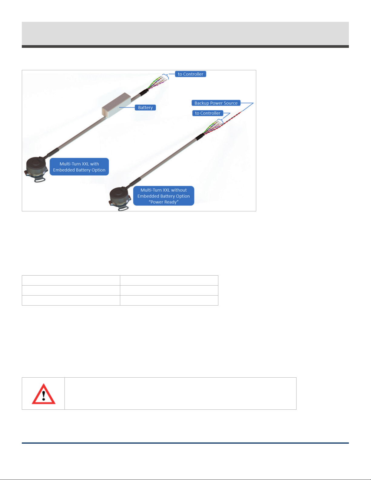
4.3 Multi-Turn Cable Options for XXL Version
The XXL version of the Model A36R can be congured with either an embedded battery cable (EB option) or a power ready cable
as shown in Figure 2 below.
PAGE 11 OF 331-800-366-5412 | encoder.com | sales@encoder.com
EPC Technical Reference Manual – Model A36R
© 2023 Encoder Products Company, REV 11/08/2023
TECHNICAL REFERENCE MANUALModel A36R
Figure 2: XXL option cable congurations
4.3.1 Low Power Option (XXL) with Embedded Battery Cable (EB)
The embedded battery cable option is ready to use upon receipt. This solution uses a Tadiran TL-5242/W battery with the
following specications:
Nominal capacity @ 1mA, to 2V 2.1 Ah
Rated voltage 3.6V
Operating temperature -55°C to 85°C
WARNING: Min/max operating temperatures for the battery may dier from the encoder. Each component shall not exceed its
respective operating temperature.
Table 3: Battery specications for EB cable
4.3.2 Low Power Option (XXL) with Power Ready Cable (no EB option)
Important: To avoid a battery error, the battery or external power source must be
connected BEFORE +VDC is applied. This applies during initial installation and backup
power source replacement. See Section 5 for detailed instructions on installation of
backup power source.

PAGE 12 OF 331-800-366-5412 | encoder.com | sales@encoder.com
EPC Technical Reference Manual – Model A36R
© 2023 Encoder Products Company, REV 11/08/2023
TECHNICAL REFERENCE MANUALModel A36R
The battery ready cable requires an external battery or power source to be supplied at VBAT+/VBAT- to have multi-turn position
data backed up during main power loss.
The electrical specications below can be used in conjunction with Table 1 and Table 2 to select a backup power solution that will
work best for your application.
VBAT Min = See Table 1
VBAT Typ = 3.6V (recommended)
VBAT Max = 5.5V
Table 4: Voltage requirements for backup power interface
VBAT voltages below the warning/error thresholds specied in Table 1 will result in warning/error ags that will appear in the data
packet. Battery error is latching and must be cleared. See Section 6.1 (manual error clear) or Section 8.6 (error clear command) for
instructions if needed.
While adequate main voltage is supplied at +VDC, the encoder draws only a tiny parasitic drain from VBAT (less than 10nA).
When main voltage at +VDC drops below the specied minimum, the encoder switches to low power mode and draws current
from the backup power source. Current draw is relative to the encoder shaft speed. See Figure 1.
5. Backup Power Installation and Replacement
Special considerations should be taken when connecting backup power to the power ready cable. Sections 5.1 and 5.2 apply only
to the power ready (standard) option. EPC does not recommend replacement of the embedded battery (EB) cable.
5.1 Backup Power Installation
When the low power option (XXL) is selected without the embedded battery option (EB), a power ready cable will be supplied. See
Section 4.3 for details. For this option, you will need to install your own battery or backup power source.
When installing your own backup power source, the following steps should be taken:
• Do not apply main voltage at +VDC. If already connected, please remove.
• Apply compatible battery or backup power source. Details to aid in backup power selection can be found in Section 4.2 and
Section 4.3.1.
• Connect main voltage at +VDC and power on the encoder.
• Verify no error or warning bits are present. See Section 6.2 for details.
See Section 4.2 for backup power specications.
If the low power option (XXL) is selected with the embedded battery option (EB), the backup power source will already be
installed an no installation is required.

PAGE 13 OF 331-800-366-5412 | encoder.com | sales@encoder.com
EPC Technical Reference Manual – Model A36R
© 2023 Encoder Products Company, REV 11/08/2023
TECHNICAL REFERENCE MANUALModel A36R
5.2 Backup Power Replacement
If backup power does need to be replaced, please follow the steps below to avoid multi-turn position data loss:
• Leave main voltage at +VDC connected and powered on.
• Swap backup power source and ensure the new source is adequate. Details on suitable backup power sources can be found in
Section 4.2 and Section 4.3.1.
• The temporary backup power loss will induce a latching battery backup error. Clear this error by issuing the clear command
(SCLR). See Section 8.6.
• If unable to issue the SCLR command, perform a physical error clear by applying 0V (COM) to the Position Preset pin (PRE) for
> 30 sec. See Section 6.1.
If the low power option (XXL) is selected with the embedded batter option (EB), the entire cable assembly will need to be replaced
if using the radial mounted header (RMH) connector option. If a cabled version needs backup power replacement, contact EPC.
6. Features
Model A36R encoders provide user features to assist in conguration and troubleshooting. This section will detail features that are
common to encoders congured with both SSI and BiSS C communication protocols. Features unique to a single communication
protocol type can be found in their respective sections later in this manual.
6.1 Preset Pin
The Model A36R oers a multi-function Position Preset pin (PRE). See wiring table in the product datasheet for details.
The Position Preset pin oers two functions:
1. Denes the current shaft position as 0 ST and 0 MT
2. Issues the SCLR command to clear all errors.
To set current shaft position to 0 ST and 0 MT (preset function), the Position Preset pin should be pulled to 0V for 2-4 sec. This can
be done manually or via controller I/O pin.
To issue the SCLR command, the Position Preset pin should be pulled to 0V for > 30 sec.
Warning: If manually issuing the SCLR command, ensure you have a rm connection while
applying 0V to the Position Preset pin. If the connection is accidentally removed and
the 0V connection duration lands in the 2-4 sec window, you will inadvertently issue the
preset command and change the current encoder position.
When not being used, the Position Preset pin can be tied to 5V or left oating.

PAGE 14 OF 331-800-366-5412 | encoder.com | sales@encoder.com
EPC Technical Reference Manual – Model A36R
© 2023 Encoder Products Company, REV 11/08/2023
TECHNICAL REFERENCE MANUALModel A36R
Warning: Voltage at the Position Preset pin cannot exceed 5V or permanent damage may
occur.
6.2 Error and Warning Monitoring
The Model A36R features an extensive error/warning reporting mechanism. Various events are captured by the encoder and
present low-active error and warning bits in the data packet for both SSI and BiSS outputs. See Figure 3 and Figure 4 below.
Figure 3: SSI data stream with nERR and nWARN for condition reporting
Figure 4: BiSS data stream with nERR and nWARN for condition reporting
If nERR or nWARN are activated, the error log and warning log can be read respectively to determine the cause. Details of these
logs can be found in Table 5 and Table 6.
The Error and Warning Registers can only be read using BiSS C. If you observe nERR or
nWARN on an SSI encoder, try the troubleshooting steps listed below, power cycle the
encoder, and try manually issuing an SCLR command with the Position Preset pin as
outlined in Section 6.1.

PAGE 15 OF 331-800-366-5412 | encoder.com | sales@encoder.com
EPC Technical Reference Manual – Model A36R
© 2023 Encoder Products Company, REV 11/08/2023
TECHNICAL REFERENCE MANUALModel A36R
Error Log: Bank 0x44, Address 0x10
Bit Condition Solution
All Units
0 Signal error
Issue SCLR command.
Power cycle device.
If error persists, return to EPC for evaluation.
1 Position error
Issue SCLR command.
Power cycle device.
If error persists, return to EPC for evaluation.
2 Startup error
Issue SCLR command.
Power cycle device.
If error persists, return to EPC for evaluation.
3 Internal memory error
Issue SCLR command.
Power cycle device.
If error persists, return to EPC for evaluation.
XXL Units
Only
4 Battery error
Voltage at VBAT has dropped below the error threshold (see Table 1). Ensure
adequate backup voltage is applied, issue SCLR command, and power
cycle if needed. Note: MT count is compromised if this error is observed.
5 Magnet error
Magnetic disc not detected. Check for excessive runout or vibration. Issue
SCLR command.
Power cycle device.
If error persists, return to EPC for evaluation.
Unused 6-7 n/a These bits are unused.
Table 5: Model A36R error log

PAGE 16 OF 331-800-366-5412 | encoder.com | sales@encoder.com
EPC Technical Reference Manual – Model A36R
© 2023 Encoder Products Company, REV 11/08/2023
TECHNICAL REFERENCE MANUALModel A36R
Warning Log: Bank 0x44, Address 0x11
Bit Condition Solution
All Units
0+VDC voltage low
warning Verify +VDC is within specied range.
1 Temp sensor not ready
Internal temperature sensor is not yet in steady state. If you are trying to
read temperature or manipulate temperature limits, wait until device is
ready.
2High temp limit
exceeded
Sensor junction temperature is above specied maximum threshold. See
Section 8.6 for setails on setting this threshold. Temperature high limit is
140° C by default.
3Low temp limit
exceeded
Sensor junction temperature below specied minimum threshold. See
Section 8.6 for setails on setting this threshold. Temperature low limit is
-40° C by default.
XXL Units
Only 4 Battery early warning Voltage at VBAT is below the early warning threshold (see Table 1). Replace
battery soon or check that external voltage source at VBAT is set correctly.
Unused 5-7 n/a These bits are unused.
Table 6: Model A36R warning log
Error and warning bits can be cleared by issuing the SCLR command or by power cycling. See Section 8.6 for details on issuing this
command. The SCLR command may also be issued manually using the Position Preset pin. See Section 6.1 for details.
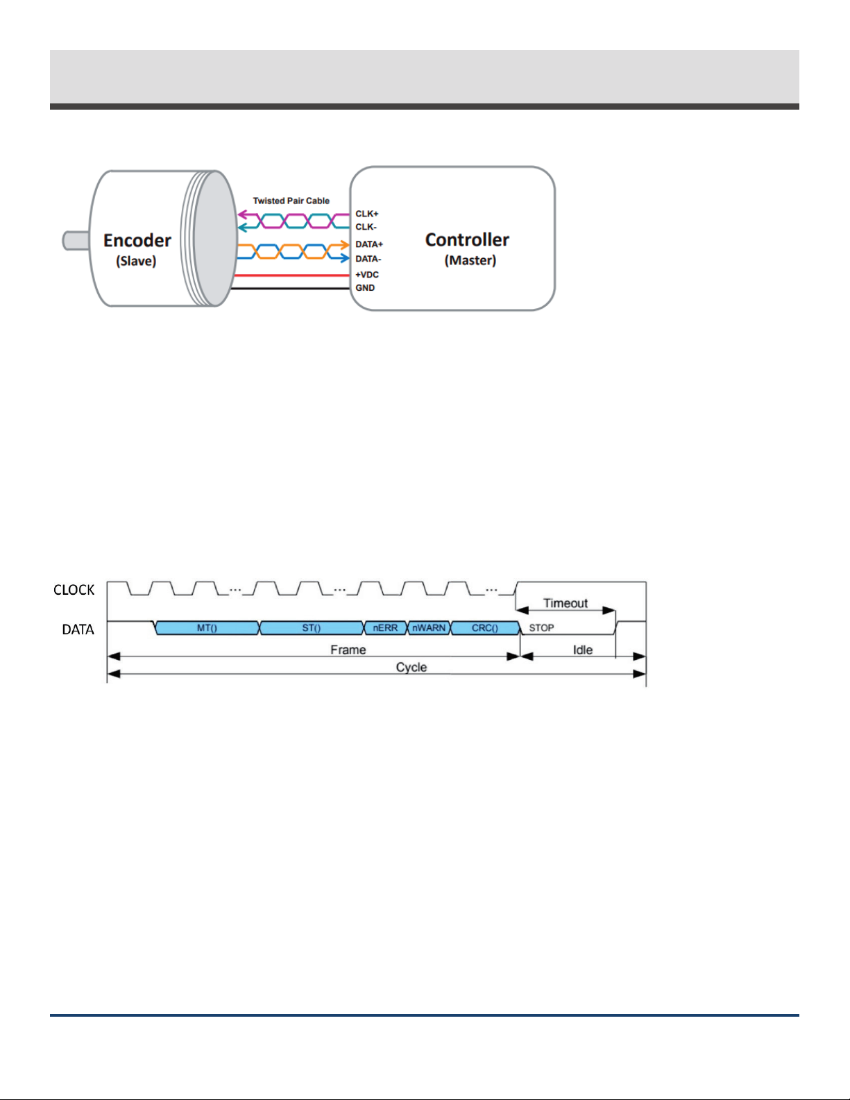
7. SSI Protocol
7.1 Overview
Synchronous Serial Interface, or SSI, is a simple serial communications protocol designed for data transfer between computers or
user terminals and smart sensors.
Model A36R encoders with SSI communication are always slave devices. The eldbus device (i.e., controller, counter) is always the
master device, supplying a clock signal to which the encoder responds synchronously.
The SSI master must be congured to the correct data length and clock rate.
The master must also be congured to display the correct data type (gray or binary) supplied by the encoder. This is determined
by the order code and cannot be changed.
PAGE 17 OF 331-800-366-5412 | encoder.com | sales@encoder.com
EPC Technical Reference Manual – Model A36R
© 2023 Encoder Products Company, REV 11/08/2023
TECHNICAL REFERENCE MANUALModel A36R
Figure 5: Typical SSI point-to-point connections
The SSI master controls the data ow from the encoder data output by sending clock pulses to the encoder clock (CLK) inputs. The
encoder electronics respond to the rst falling edge of the clock sequence by freezing the current position value and starting the
serial output of the data bits. On every following rising clock edge from the master, one data bit is transmitted by the encoder.
Additional details on timing and data structure can be found in the next section.
7.2 SSI Packet Structure
The data frame for the Model A36R with SSI protocol is shown in Figure 6 below.
Figure 6: SSI data exchange
The data frame consists of multi-turn position data (right-aligned), single-turn position data (left-aligned), low-active err bit nERR,
low-active warning bit nWARN, and a 6-bit CRC.
If the encoder was congured with no multi-turn bits, only single-turn position data will be sent.
nERR and nWARN can be monitored to provide indication of encoder errors and warnings respectively. See Section 6.2 for details.
Battery early warning and battery error will trigger these bits as well for encoders congured with the low power backup (XXL)
option.
The 6-bit CRC can be used to provide error checking to the critical encoder position data. Further details on CRC can be found in
Section 9. A 16-bit CRC is available upon special request. Please contact EPC if this option is required.
PAGE 18 OF 331-800-366-5412 | encoder.com | sales@encoder.com
EPC Technical Reference Manual – Model A36R
© 2023 Encoder Products Company, REV 11/08/2023
TECHNICAL REFERENCE MANUALModel A36R
If only position data is needed, it is possible to send only the number of clock cycles
matching the position bit length (MT + ST bits) to disregard the nERR/nWARN and CRC
bits at the end of the packet.
An optional 6-bit life cycle counter is also available upon special request. Please contact EPC if this option is required.
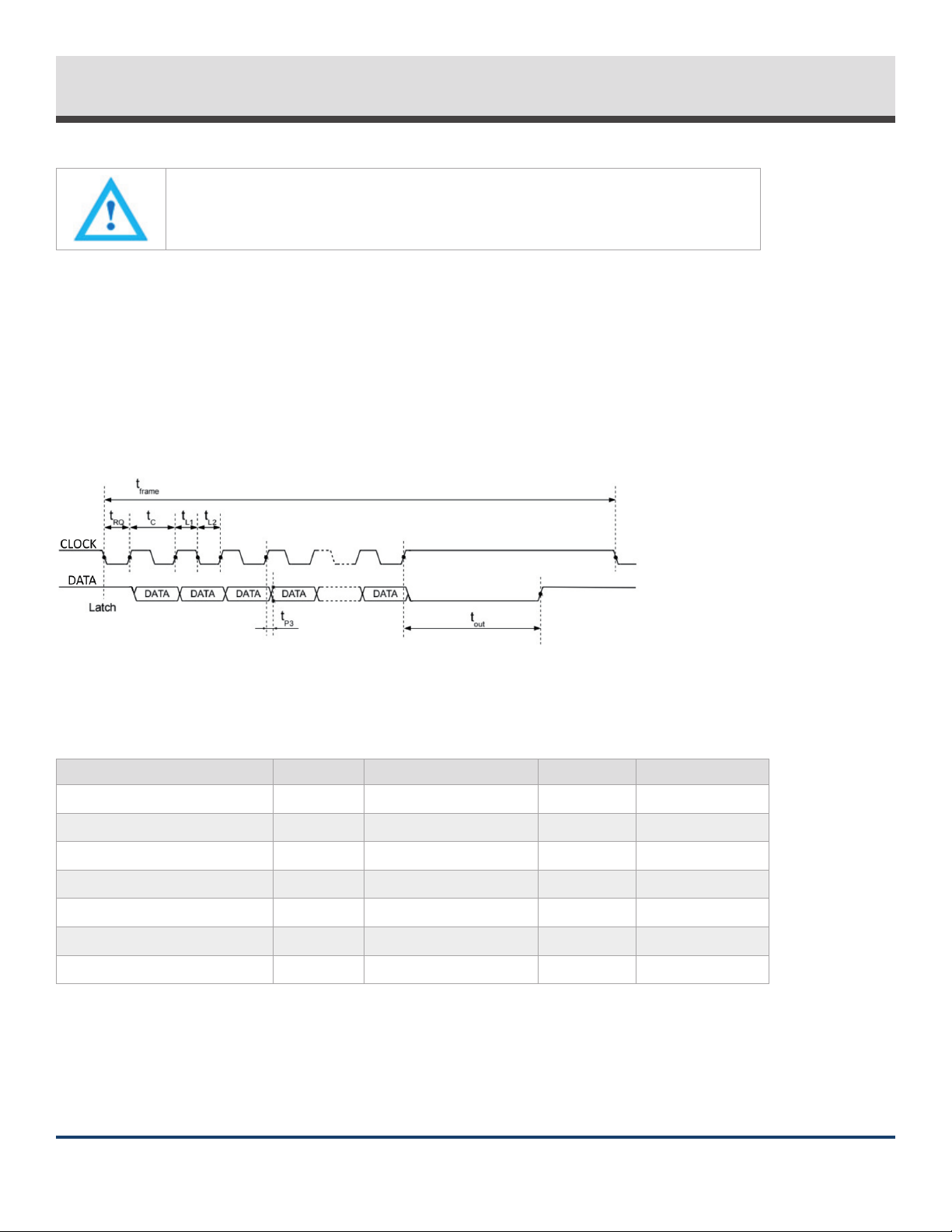
7.3 SSI Communication Timing
Communication via SSI requires slave timeout (tout) be met before additional clock signals may be sent. If tout is not met, the
encoder will resend the same information and will not latch the updated position. Figure 7 and Table 7 below provide details on
timing requirements while using the Model A36R with SSI.
Figure 7: SSI timing diagram
Parameter Symbol Min Typ Max
Permissible Frame Repetition tframe Allow tout to elapse -- Indenite
REQ Signal Low Level Duration tRQ 50 ns -- --
Permissible Clock Period tC200 ns -- --
Clock Signal High Level Duration tL1 25 ns - tout
Clock Signal Low Level Duration tL2 25 ns -- tout
Propagation Delay tp3 -- -- 132 ns*
Slave Timeout tout 16 s 20 s 24 s
*May increase with long cable lengths.
Table 7: SSI timing and performance characteristics

PAGE 19 OF 331-800-366-5412 | encoder.com | sales@encoder.com
EPC Technical Reference Manual – Model A36R
© 2023 Encoder Products Company, REV 11/08/2023
TECHNICAL REFERENCE MANUALModel A36R
7.4 Cable Length vs. Frequency
The maximum clock frequency supplied by the master is limited by cable length.
Cable Length Max Clock Frequency
< 1 m (3.2 ft) 5 MHz
< 35 m (115 ft) 1.7 MHz
< 60 m (197 ft) 1.0 MHz
<150 m (492 ft) 500 kHz
< 240 m (787 ft) 333 kHz
> 240 m Not advised. Contact EPC if required.
Note: This assumes shielded twisted pair cable and proper termination are used. Lower clock frequency may be required at
extreme cable lengths. Although these clock frequencies are possible, limiting frequency for SSI is advised for best performance.
Table 8: Cable length vs. max clock frequency (SSI)
An additional consideration with long cable lengths is voltage drop. Be advised that the minimum specied voltage at +VDC
for this encoder must be met at the encoder. Long cable lengths equate to more voltage dropped on the cable and must be
considered.
8. BiSS C Protocol
8.1 Overview
BiSS C is an open-source digital interface for sensors and actuators. BiSS is hardware compatible with the industrial standard SSI
(Serial Synchronous Interface), but oers additional feature and options:
• Two unidirectional lines
• Cyclic at high speed (up to 10MHz possible using RS422)
• Line delay compensation for high-speed data transfer
• Request processing times for data generation at slaves
• Error checking: CRC, errors, warnings
Model A36R encoders with BiSS C communication are always slave devices. The eldbus device (i.e., controller, counter) is always
the master device, supplying a clock signal to which the encoder responds synchronously. This uses the same point-to-point
conguration as SSI with two sets of dierential signals: Clock and Data.
BiSS C uses Control Data (CD) bits in both the master data stream, Control Data Master (CDM), and the slave data stream, Control
Data Slave (CDS). These bits permit the reading from and writing to slave registers and the sending of commands to slave devices
one bit at a time across multiple data packets.

PAGE 20 OF 331-800-366-5412 | encoder.com | sales@encoder.com
EPC Technical Reference Manual – Model A36R
© 2023 Encoder Products Company, REV 11/08/2023
TECHNICAL REFERENCE MANUALModel A36R
BiSS C can be implemented via user hardware according to the documentation provided by iC Haus at: biss-interface.com. iC Haus
oers various hardware solutions to facilitate BiSS C integration:
• iC-MB4 (BiSS Master Interface IC)
• iC-MB5U (BiSS-to-USB Adaptor)
Additional information regarding the BiSS C protocol can be found at the BiSS Interface website: biss-interface.com
8.2 BiSS C Packet Structure
The data frame for Model A36R encoders with BiSS C protocol is shown in Figure 8 below.
Figure 8: BiSS data exchange
The data frame includes a start bit, Control Data Slave (CDS), and Single Cycle Data (SCD). The SCD is the portion in blue in Figure 8
and includes the multi-turn position data (right-aligned), single-turn position data (left-aligned), low-active error bit nERR,
low-active warning bit nWARN, and a 6-bit CRC.
If the encoder was congured with no multi-turn bits, only single-turn position data will be sent.
nERR and nWARN can be monitored to provide indication of encoder errors and warnings respectively. See Section 6.2 for details.
Battery early warning and battery error will trigger these bits as well for encoders congured with the low power backup (XXL)
option.
The 6-bit CRC can be used to provide error checking to the critical encoder position data. Further details on CRC can be found in
Section 9. A 16-bit CRC is available upon special request. Please contact EPC if this option is required.
An optional 6-bit life cycle counter is also available upon special request. Please contact EPC if this option is required.
8.3 BiSS C Communication Timing
The encoder data is latched on the rst rising clock edge. The encoder then delays its start bit and subsequent data transmission
for time (tbusy). After all data is transmitted, the encoder requires the timeout (tout) be met before additional clock pulses are sent
to initiate the next frame. See Figure 9 and Table 9 below for timing details.
This manual suits for next models
2
Table of contents
Other Encoder Media Converter manuals


Popular Media Converter manuals by other brands


Linear Technology
Linear Technology LT1952-1 quick start guide

ELPRO
ELPRO KM03-HE02 Series quick start guide

Magewell
Magewell Director Mini user manual

Avenview
Avenview DVI-PROWALL-12X manual

ADS Technologies
ADS Technologies HDUP-1500 operating instructions

PR electronics
PR electronics 3103 product manual