ENCON SHOWER SHELTER User manual
Doc. No: 01999929
Revision: C 1 of 10
Issue Date: 08/15/21
INSTALLATION
•
OPERATION
•
MAINTENANCE MANUAL
SHOWER SHELTER™
FIELD ASSEMBLED SHOWER STRUCTURE
PRODUCT DESCRIPTION
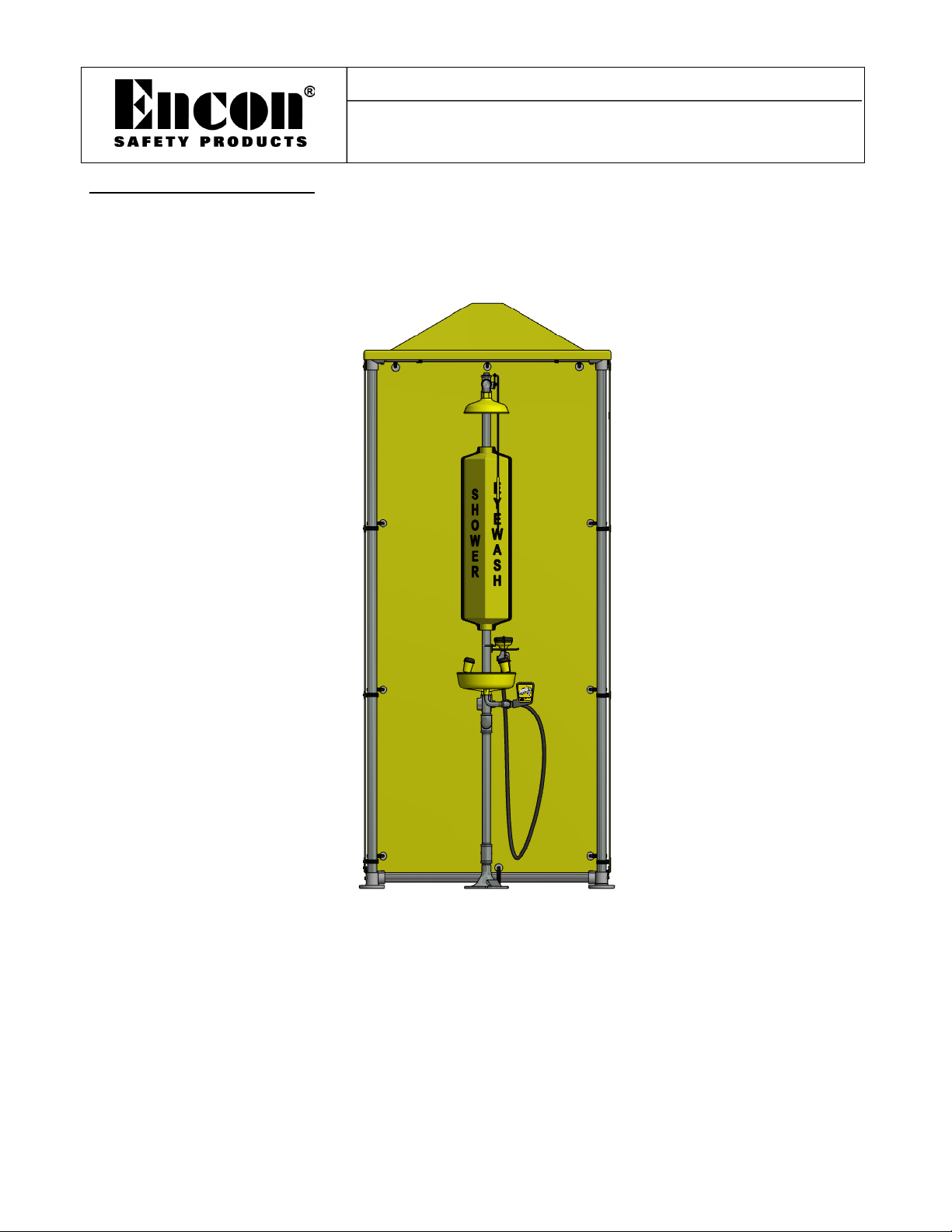
The Shower Shelter™ is a field assembled three sided wind break. A single model with optional accessories including area
lights, graphics and modesty curtain is available. The Shower Shelter™ instruction manual is included with each unit,
installation instructions regarding the kit accessories are included in each kit. The shelter is designed to be field fit to existing
emergency shower/eyewash equipment by locating the structure over or around the shower equipment.
FIGURE 1 (MODEL 01080024)
The shower equipment may be located in the right or left rear corner or the center in the rear of the structure. Thermaflow®’s
with 32” overhead section (w/drench hose) should be mounted in the rear corner only. Assembly of the enclosure will require
two people, approximately a 12’ x 12’ assembly/staging area and the tools as itemized in the manual. Approximate assembly
time is three man hours. The panel/clamp assemblies are designed to allow for thermal expansion, do not rigidly mount
panels.
NOTE: It is advisable to assemble the Shower Shelter™ framework and locate over/around the emergency shower
prior to assembly of panels as the water inlet through a panel (side or rear) will be determined by the shower water
supply inlet to the shelter orientation.

Doc. No: 01999929
Revision: C 2 of 10
Issue Date: 08/15/21
INSTALLATION INSTRUCTIONS
(Prior to assembly the parts must be reviewed enabling the assemblers to construct the units correctly in the least amount of
time, the first time. Should questions arise during assembly contact Encon Safety Products at 800-283-6266.
COMPONENT IDETIFICATION/PARTS LIST
ITEM NO.
NOMENCLATURE
QUANTITY
PART NO.
1
BOTTOM FRONT CONNECTOR TEE
2
00011506
2
TOP CONNECTOR TEE
4
00011529
3
BOTTOM REAR CONNECTOR ELBOW
2
00011507
4
FLOOR SUPPORT FLANGE
4
00011613
5
SCREW
38
00012805
6
FENDER WASHER
76
00012788
7
PANEL CUSHION CLAMP
38
00013115
8
LOCK NUT
38
00011201
9
VERTICAL STRUCTURE SUPPORT
4
00010179
10
HORIZONTAL SIDE SUPPORT
4
00000159
11
FRONT AND REAR HORIZONTAL SUPPORT
3
00000158
12
SIDE PANEL
2
01110214
13
REAR PANEL
1
01110214
14
ROOF
1
01110213
15
CONNECTOR HEX SCREW (NOT SHOWN INCLUDED W/PART)
-
00012618
16
HEX WRENCH
1
00011532
17
INSTRUCTION SHEET
-
01999929
NOTE:ALL PARTS SHOUD BE REVIEWED WITH ILLUSTRATIONS PRIOR TO ASSEMBLY.
PART I
SHOWER SHELTER™ STRUCTURE ASSEMBLY INSTRUCTIONS
1. Inspect shipping container for damage. If exterior damage is observed, file a freight claim with the freight carrier as
itemized on the invoice
2. Unpack shipping container contents and inventory against the parts list in the installation manual (see above).
3. Identify and locate the appropriate tools for assembly which include:
a. Pipe Wrench
b. Hex Wrench(included)
c. Flat Blade Screw Driver
d. Ratchet & 7/16” Socket
e. ½” Anchor Bolts as required
f. 6’ Step Ladder
g. Hole Saw
4. Set aside all nuts and bolts, washers, clamps, panels, and roof to be utilized in assembly instructions part’s II, III, IV,
& V. SEE FIGURE’S 2 & 4.
5. Lay out pipe and structural connections in an area of sufficient size to accommodate construction. The minimum
recommended area for construction is 12’ x 12’. SEE FIGURE 3.
Doc. No: 01999929
Revision: C 3 of 10
Issue Date: 08/15/21
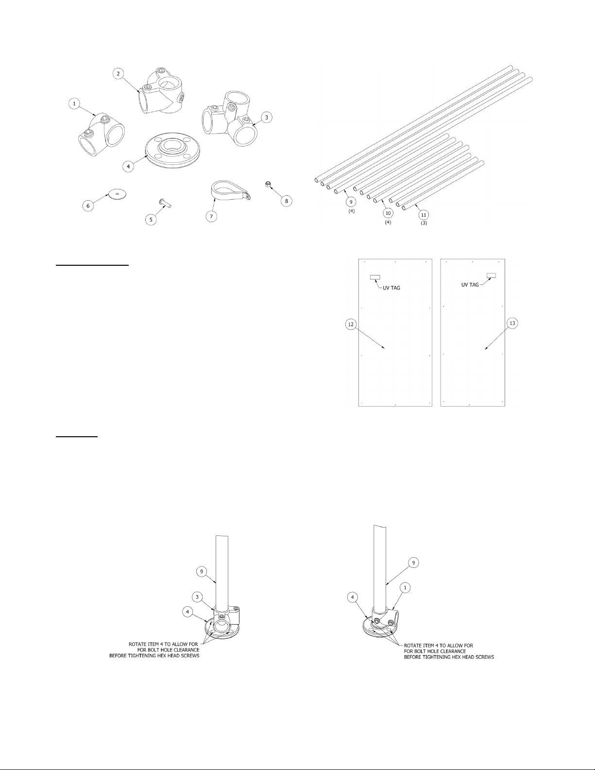
FIGURE 2 FIGURE 3
PARTS SHOWN
1. Bottom Front Connector Tees (x2)
2. Top Connector Tee (x4)
3. Bottom Rear Connector Tee (x2)
4. Floor Support Flange (x4)
5. Screw (x38)
6. Fender Washer (x76)
7. Panel Clamp (x38)
8. Lock Nut (x38)
9. Vertical Structural Support (x4)
10. Side Horizontal Support (x4)
11. Front & Rear Horizontal Support (x3)
12. Right & Left Side Panel (x2)
13. Rear Panel (x1)
PART II FIGURE 4
SIDE STRUCTURE ASSEMBLY – USE ILLUSTRATIONS AS NOTED
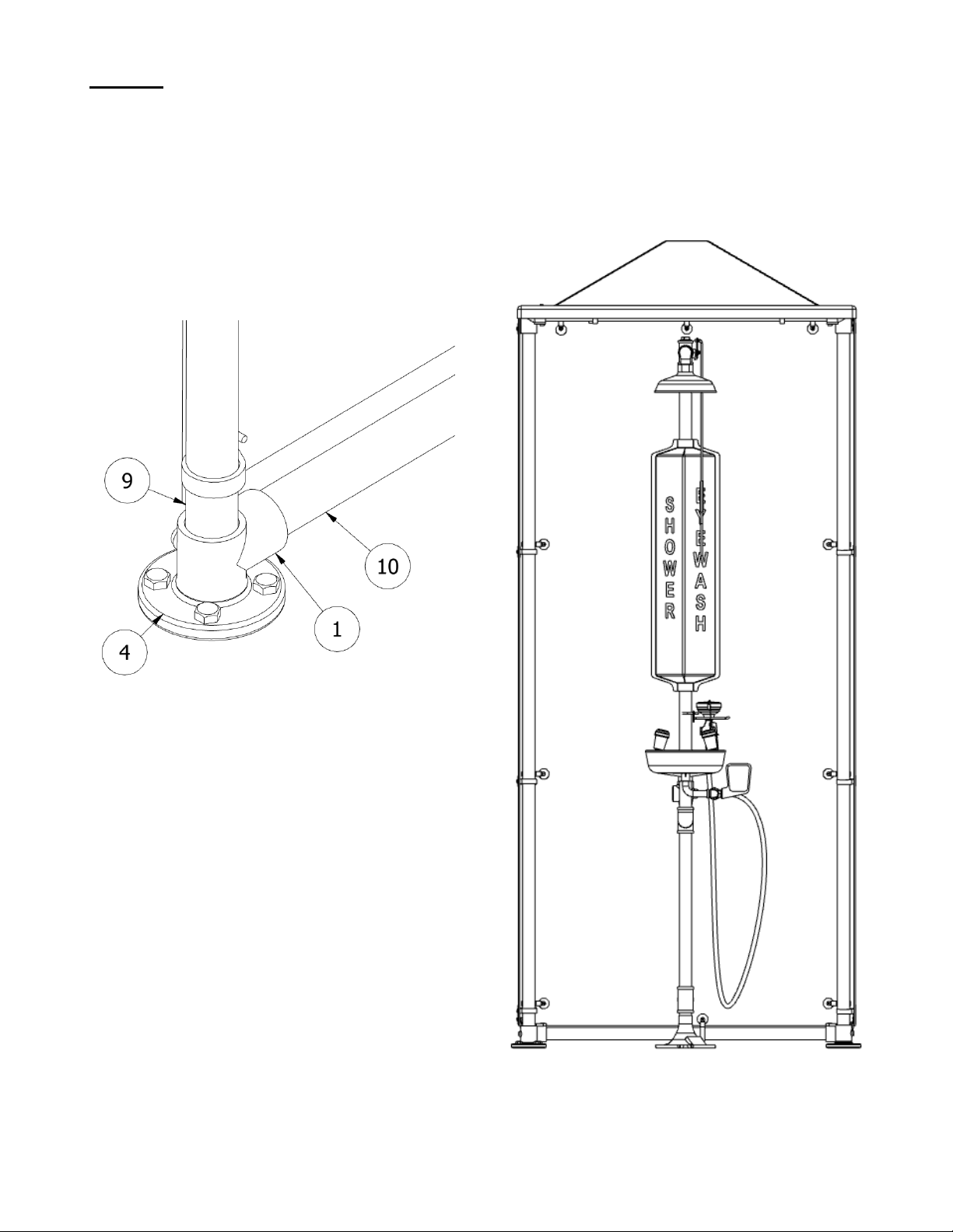
1. Slide ITEM 3 over threaded end of ITEM 9 and thread ITEM 4 creating a front vertical stanchion. SEE FIGURE 5.
Note: Tighten ITEM 4 to ITEM 9 aligning bolt holes such that sufficient room for bolt placement is available
(see note on FIGURE 5).
2. Place ITEM 1 over ITEM 9 and thread ITEM 4. SEE FIGURE 6. Note: Tighten ITEM 4 to ITEM 9 aligning bolt
holes such that sufficient room for bolt placement is available (see note on FIGURE 6).
FIGURE 5 FIGURE 6
Doc. No: 01999929
Revision: C 4 of 10
Issue Date: 08/15/21
3. After adjusting each instance of ITEM 4 to assure bolt insertion clearance, tighten hex head set screws on ITEM 1
and ITEM 3. SEE FIGURE 5 & 6.
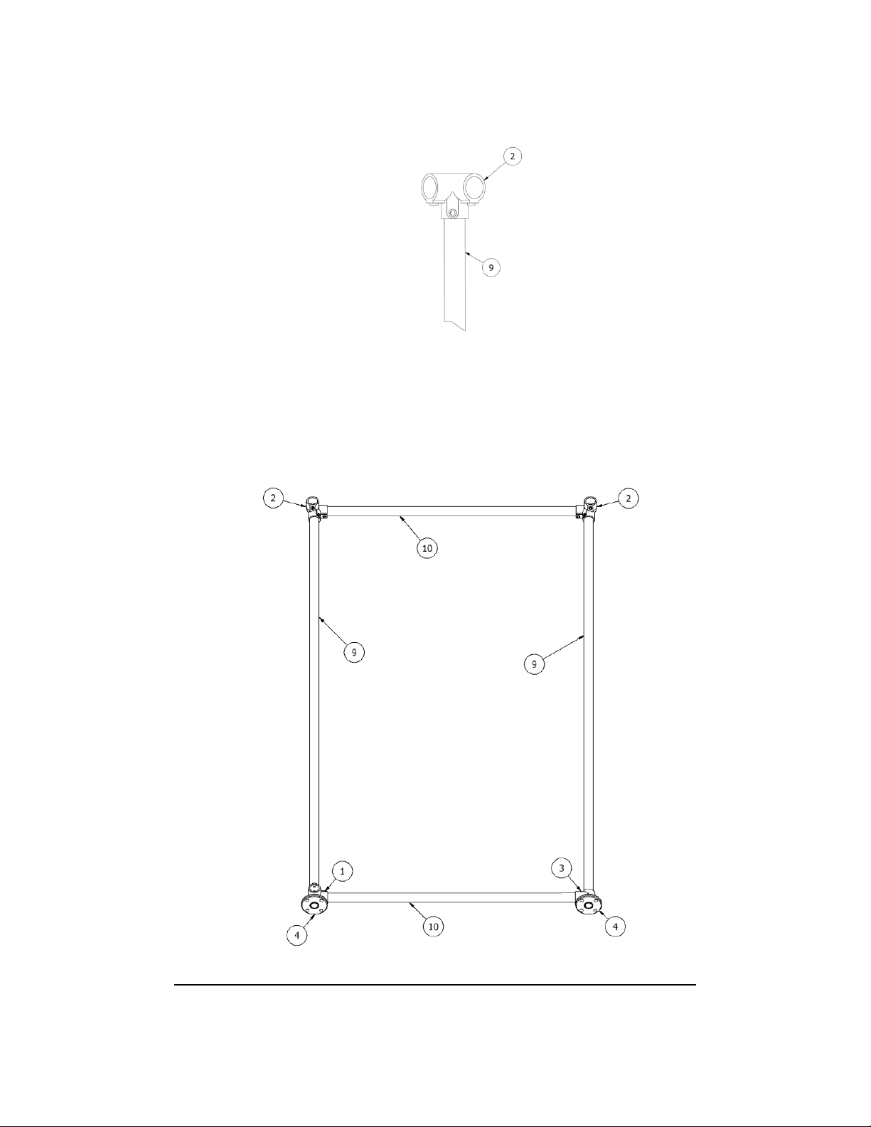
4. Place ITEM 2 on the top of ITEM 9(used in step 1 and/or 2) and push the tee fitting in place assuring that the fitting
is firmly seated on the vertical support pipe. Lock in place by tightening hex set screw. SEE FIGURE 7. Repeat for
other side.
FIGURE 7
5. Insert ITEM 10 into ITEM 2(used in step 4) and place other end of ITEM 10 into the other ITEM 2(used in step 4).
Tighten hex screws. SEE FIGURE 8.
6. Insert another ITEM 10 into ITEM 3(used in step 1) and place other end of ITEM 10 into ITEM 1(used in step 2)
Tighten hex screws. SEE FIGURE 8.
7. Repeat steps 1-6 to assemble second side of shower shelter structure.
FIGURE 8 (Right Side Constructed illustrating all structural component parts)
Doc. No: 01999929
Revision: C 5 of 10
Issue Date: 08/15/21
PART III
FRONT AND REAR STRUCURE ASSEMBLY.
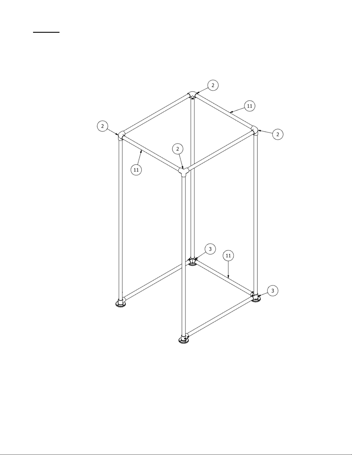
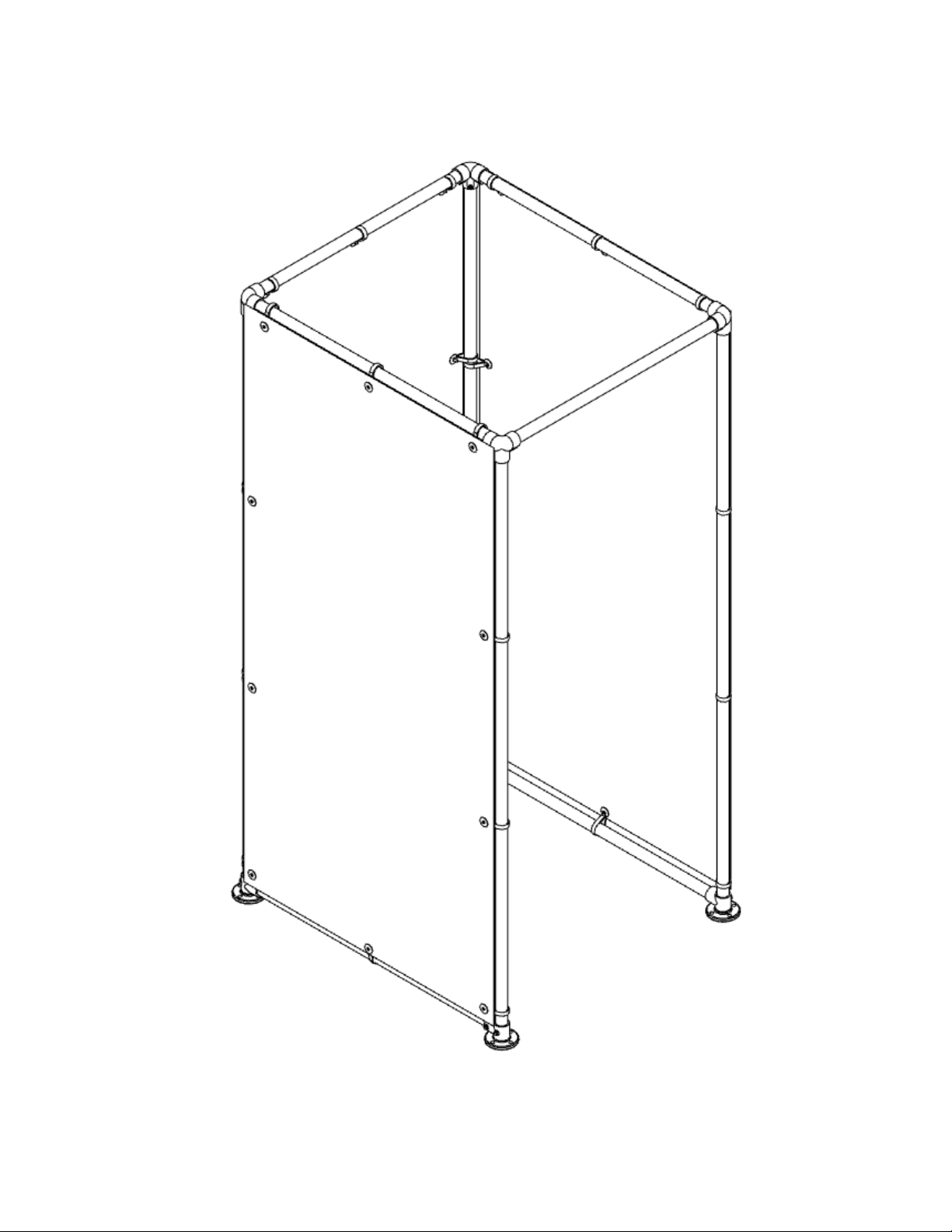
1. Connect the side structures created in PART II by inserting (2) ITEM 11’s between the ITEM 2’s at the top, and by
inserting (1) ITEM 11 between the ITEM 3’s at the bottom. Tighten hex screws. SEE FIGURE 9.
FIGURE 9
2. Raise structure and locate near the shower equipment. If required remove the ITEM 11 located on the bottom to
allow the structure to be placed around the shower equipment reconnect ITEM 11 afterwards.
Doc. No: 01999929
Revision: C 6 of 10
Issue Date: 08/15/21
PART IV
PANEL ASSEMBLY
Prior to proceeding; with hole saw, cut hole in the appropriate panel as required to accommodate the
water supply line.
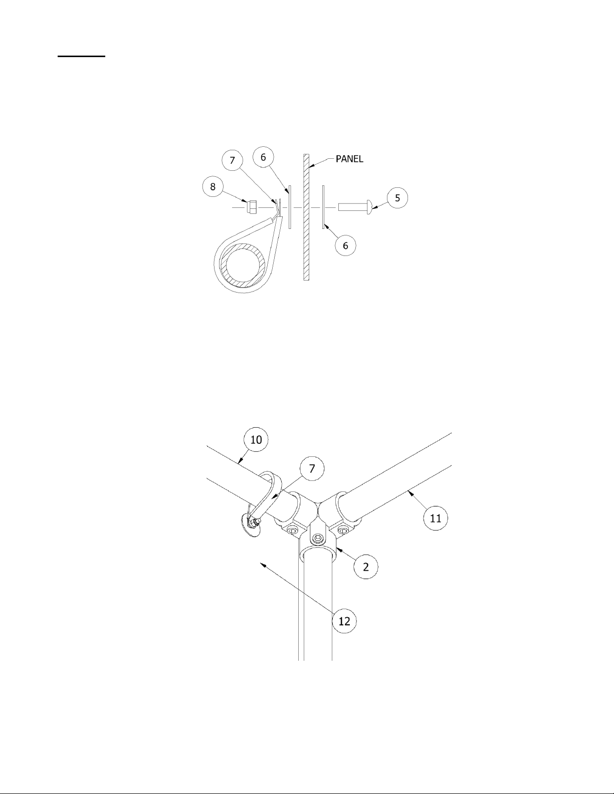
1. Locate (1) ITEM 5 , (2) ITEM 6’s, (1) ITEM 7, and (1) ITEM 8. SEE FIGURE 10.
FIGURE 10
2. Place ITEM 5 in ITEM 6 and insert into top center hole of ITEM 12. Place ITEM 7 over ITEM 10 with flat side
towards panel; SEE FIGURE 10. Lift ITEM 12 with UV tag side out onto ITEM 7 and attach as follows; with ITEM 7
on ITEM 10, place ITEM 6 over ITEM 5 followed by ITEM 7 such that the flat side of the clamp lies against the
fender washer. Tighten ITEM 8. SEE FIGURE’S 10 & 11.
Note: Panel can be supported by single top center clamp. Center panel on structure prior to attachment of
additional clamps.
FIGURE 11
Top Left Front Corner
Doc. No: 01999929
Revision: C 7 of 10
Issue Date: 08/15/21
3. With ITEM 13 proceed as in Steps 1 & 2 of panel assembly instructions assuring that the panel is centered prior to
attachment of clamps. SEE FIGURES 10 & 11.
4. Repeat Steps 1 & 2 for the right side panel. SEE FIGURES 10 & 11.
5. Attach all remaining side and rear panel clamps flat side towards the panel. SEE FIGURE 12.
FIGURE 12
Doc. No: 01999929
Revision: C 8 of 10
Issue Date: 08/15/21
PART V
ROOF ASSEMBLY
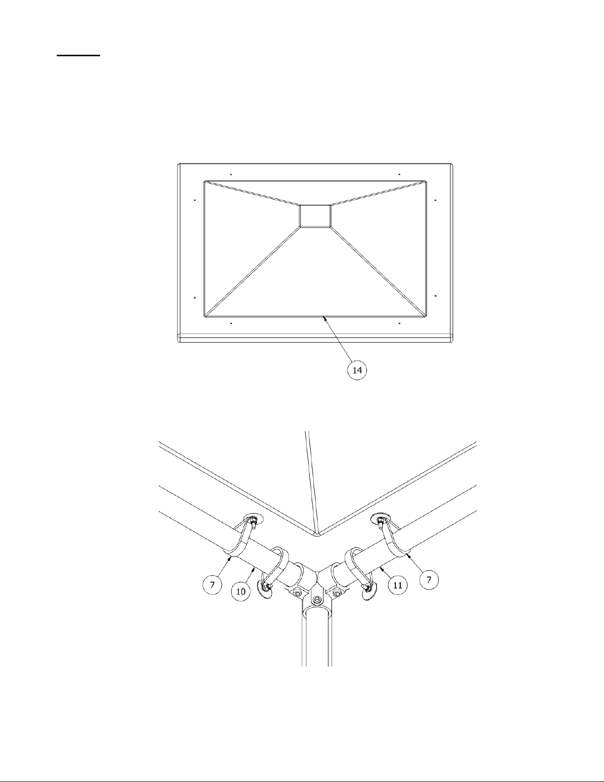
1. Locate (2) ITEM 7’S and place them flat sides up and out at the corners of ITEMS 10 & 11. SEE FIGURE 14.
2. Place ITEM 14 over structure and fasten clamps to roof as in STEP 2 of PART IV. Note: Do not tighten until all
clamps are in place with nuts on screws. SEE FIGURE’S 13 & 14.
3. Tighten ITEM 8 on all roof clamps. SEE FIGURE 14
4. Remove UV decals from the panels.
FIGURE 13
ITEM 4 - Roof
FIGURE 14
Roof, Rear & Side Panels Assembled
Doc. No: 01999929
Revision: C 9 of 10
Issue Date: 08/15/21
PART VI
SECURING ASSEMBLY TO FOUNDATION
1. Tighten (4) ITEM 4 aligning bolt holes such that sufficient room for bolt placement is available.
2. Mark bolt holes on pad and install anchor bolts (supplied by others), washer and lock nuts after placing structure
over foundation. SEE FIGURE 15.
3. Inspect finished product for tight clamps, joints and panels. SEE FIGURE 16.
FIGURE 15
FIGURE 16
Finished Shower Shelter™
Assembly

Doc. No: 01999929
Revision: C 10 of 10
Issue Date: 08/15/21
OPERATION & MAINTENANCE
1. Plumbed units shall be activated weekly to flush lines and verify proper flow pattern and volume.
2. Test records should be maintained verifying compliance with testing procedures.
3. Some chemical vapors or liquids may damage or soften plastic materials. Precaution should be taken to determine
compatibility prior to installation.
TRAINING
All employees who might be exposed to hazardous material shall be instructed in the location and proper use of emergency
shower and eye/facewash units. Experiences have shown that initial first-aid treatment for irritates should be to wash the eyes
and face for 15 minutes prior to medical treatment. It is important to hold the eyelids open and roll the eyes so water will flow
on all surfaces and in the folds surrounding the eyes.
PROPOSITION 65
WARNING: This product can expose you to BPA, which is known to the State of California to cause birth defects or other
reproductive harm. For more information go to www.P65Warnings.ca.gov.
WARRANTY STATEMENT
ENCON HEREBY DISCLAIMS ALL WARRANTIES EXPRESSED OR IMPLIED INCLUDING BUT NOT LIMITED TO
WARRANTIES OF MERCHANTABILITY, FITNESS FOR A PARTICULAR PURPOSE, AND NON-INFRINGEMENT OF
THIRD-PARTY RIGHTS, EXCEPT AS HEREINAFTER PROVIDED.
Encon Safety Products warrants that for one year from the date of purchase of any Encon products, the product will be free of
defects in materials and workmanship if properly used and cared for or cleaned under normal conditions in accordance with
Encon’s use and care instructions and properly installed, if applicable, in accordance with Encon’s installation instructions.
With respect to the product, Encon’s only obligation and purchaser’s exclusive remedy under this warranty is to repair or
replace such product; provided that:
1. Encon is notified of the defect within one year of shipment, and
2. the product is determined by Encon to be defective.
Encon requires proof of original ownership as proof of warranty coverage, and Encon must receive any claim under this Limited
Warranty within one year of purchase of the product.
NOTWITHSTANDING ANYTHING TO THE CONTRARY CONTAINED HEREIN, ENCON SHALL NOT BE LIABLE FOR
LOSS, DAMAGE, OR EXPENSE ARISING DIRECTLY OR INDIRECTLY AS A CONSEQUENCE OF USE OF THE
EQUIPMENT WITH OTHER PRODUCTS OR FROM ANY OTHER CAUSE, INCLUDING ANY CONSEQUENTIAL,
INCIDENTAL, SPECIAL OR EXEMPLARY DAMAGES, EXCEPT FOR ENCON’S OBLIGATION TO REPAIR OR REPLACE
DEFECTIVE PRODUCTS AS EXPRESSLY PROVIDED IN THIS STATEMENT.
Replacement parts purchased from Encon are warranted for one year following the shipment of such replacement part, or until
the expiration of the warranty period for the product, whichever is less. No warranty is given in connection with products that
are altered without Encon’s expressed written consent. The same warranty limitations and the obligations of Encon as set out
herein above shall apply to replacement parts.
Encon’s total liability arising out of this warranty (including, but not limited to, warranty claims) regardless of forum and
regardless of whether such action or claim is based on tort, contract or otherwise will not exceed the total purchase price of
the product.
6825 W. Sam Houston Pkwy. N
Houston, TX 77041
1-800-AT-ENCON / 1-800-283-6266
http://www.enconsafety.com
Table of contents
Other ENCON Plumbing Product manuals


